



Abstract
The Kalina cycle is a binary mixture power generation system optimised for a range of waste heat recovery applications, which has received considerable attention as an energy efficient power generation cycle well suited to Indian climatic conditions. The Kalina cycle makes use of a binary mixture system which utilises ammonia–water mixture as a working fluid. First law and second law analysis were examined on two different Kalina cycle configurations (low temperature and medium temperature Kalina systems). The low temperature series heaters Kalina cycle system is driven with renewable energy source, while medium temperature is generally used for hot stream of energy from boiling water nuclear reactor or pressurised water nuclear reactor. The specific work output, energy, exergy and relative efficiencies have been optimized with the parameters considered. Separator temperature and turbine concentration (separator inlet concentration, x3 for Medium temperature Kalina cycle system (MTKCS) and separator vapour concentration, x11 for Low temperature Kalina cycle system (LTKCS)) are treated as common parameters between the two Kalina cycle systems. The optimum separator temperature for low temperature Kalina cycle systems with series heat exchangers and medium temperature Kalina cycle systems is in the ranges 110–150°C and 70–100°C, respectively, and the turbine concentration between 0.85–0.97 and 0.77–0.86. The highest exergy efficiency observed in the study (82%) occurred for the MTKCS, which exhibits lower exergy losses than the LTKCS, due to its more efficient energy recovery. The results identify that Kalina cycle systems can well adapt for medium temperature applications.
Introduction
Ammonia is environmentally benign and does not promote ozone depletion or global warming as organic fluids do. In the Kalina cycle, ammonia as a working fluid has zero oxygen depletion potential, near-zero global warming potential and is not highly flammable. By contrast, organic Rankine cycle (ORC) working fluids have worse environmental performance than ammonia and many are highly flammable. Organic fluid spills and emissions can lead to serious hazards if not controlled through proper safety procedures and planning. According to the literature, impressive performance advantages of Kalina cycles over ORCs have been observed. Naser Shokati et al. 1 have performed an exergoeconomic analysis of absorption power and cooling cogeneration of Kalina cycles. The highest levels of exergy destruction result from the boiler and low-pressure absorber. The five objective functions identified are the minimum unit cost of products, maximum energy and exergy efficiencies, minimum unit cost of produced exergy, minimum of the sum of exergy destruction and capital investment cost rates. 2 Jouan Rashidi and Changkyoo Yoo 3 have identified the key parameters in evaluating the energy efficiency and cooling generation of the system: ammonia mass fraction of the working fluid, absorber pressure, turbine inlet pressure and flash tank pressure. Bahram Ghorbani et al. 4 have examined a trigeneration system with the Kalina cycle power generation system. They concluded that the high exergy destruction results from the solar collectors, auxiliary boiler and heat exchangers.
Shankar and Srinivas 5 compared Kalina Cooling Cogeneration with once-through and split cycles. The highest energy utilisation was observed for the once-through cycle. Asou et al. 15 have compared Kalina cycle and conventional ocean thermal energy conversion system with ammonia–water mixture as working fluid. Dejfors et al. 6 suggested that a higher maximum pressure could improve the performance of a binary mixture cycle. Hatem 7 has presented an experimental study on ammonia vapour in an ammonia–water solution.
Koroneos and Rovas 8 compared coal/diesel system with vapor-dominated system and concluded that the latter system is economic. Korobitsyn 9 examined combined power generation systems and suggested as advanced thermal conversion methods. Shankar Ganesh and Srinivas10,11 examined two different Kalina cycle systems suitable for low temperature applications. Shankar Ganesh and Srinivas 14 have implemented the procedure extended from Gibbs free energy equations in finding the thermophysical properties. The LTKCS, and MTKCS and HTKCS formulations are considered from literature.10–13 Kalina cycle system is a flexible system suitable for generating power at low, medium and high temperature heat recoveries. In combined cooling and power generation systems too KCS can be extended.
Performance details of the Kalina cycle with source temperature.

Table 1 results the innovations and the performance data for Kalina Cycle Systems. The objective of the present work is to investigate two different Kalina cycle systems (KCS) designed for low and medium-temperature heat recovery. The thermodynamic properties of the two systems have been evaluated using MATLAB. Based on the system components, the separator temperature and turbine concentration have been chosen as common parameters for parametric evaluation.
Properties of binary ammonia–water mixture
The ammonia–water mixture properties were developed from the literature reported.32–34, Based on the references, the correlations have been considered in evaluating the properties of binary ammonia–water mixture up to high temperature KCS. Figure 1 shows the enthalpy–concentration plot as function of ammonia concentration and pressure. Both the low-temperature and medium-temperature Kalina cycle systems (LTKCS and MTKCS) have been modelled with ammonia–water mixture properties calculated up to 100 bar pressure by Shankar Ganesh and Srinivas.14 The model trends are in good agreement with experimental data up to 100 bar. The three curves (liquid enthalpy curve, vapour enthalpy curve and auxiliary curve) provide the thermodynamic property values. The properties have been generated using MATLAB.
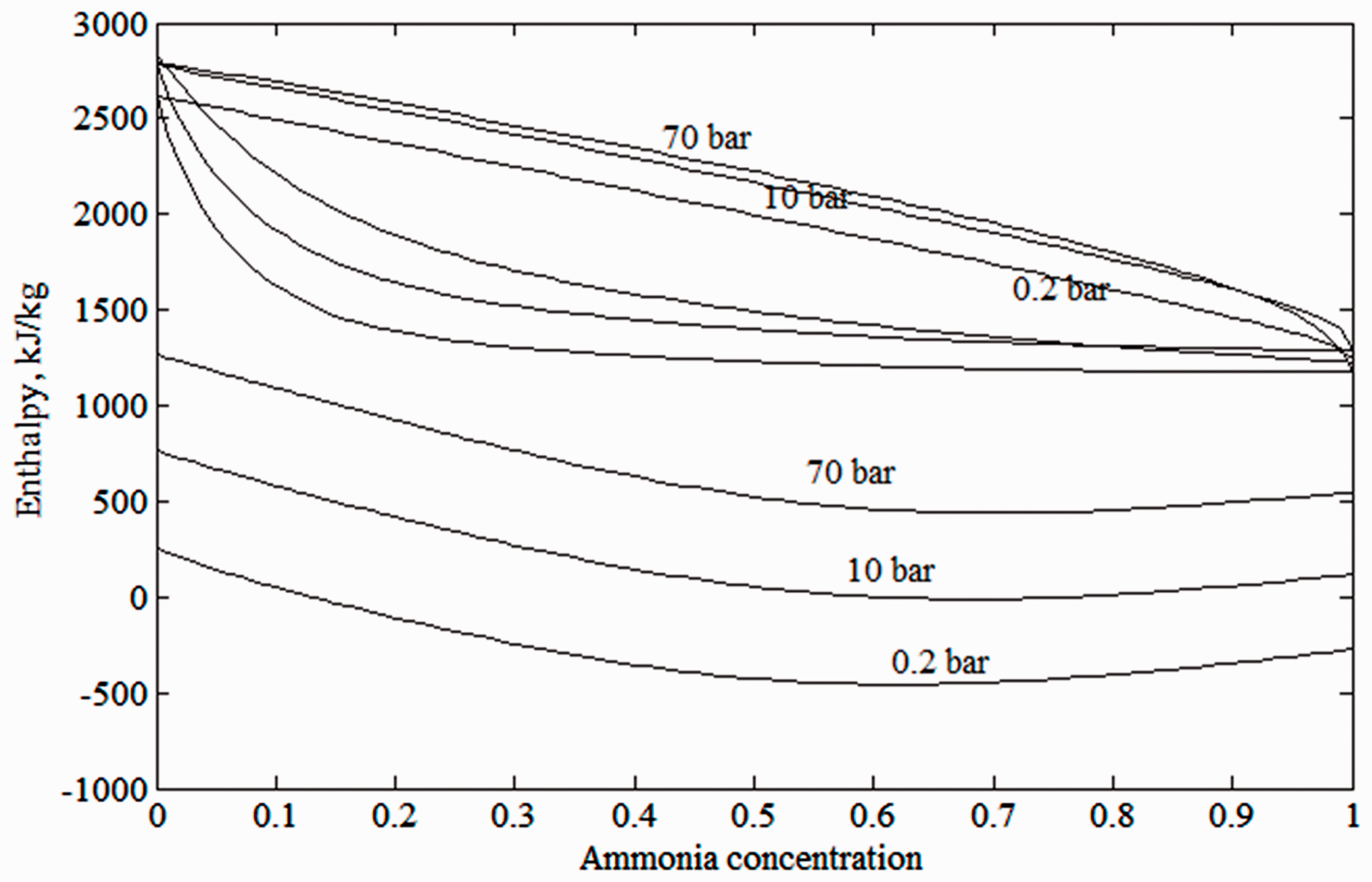
Ammonia–water enthalpy concentration diagram.
Figure 1 shows the enthalpy–concentration plot as function of ammonia concentration and pressure. Both the low-temperature and medium-temperature Kalina cycle systems (LTKCS and MTKCS) have been modelled with ammonia–water mixture properties calculated up to 100 bar pressure. 14 The model trends are in good agreement with experimental data up to 100 bar. The three curves (liquid enthalpy curve, vapour enthalpy curve and auxiliary curve) provide the thermodynamic property values. The properties have been generated using MATLAB.
Thermodynamic modelling of the Kalina power plant for low and medium-temperature heat recovery
An LTKCS, depicted in Figure 2, has been investigated in order to optimise heat recovery from solar thermal collectors. The low temperature Kalina power plant works with a hot source temperature up to 150°C. The high and low pressure forms operate at pressures of 35 and 10 bar, respectively. The components, i.e. the high temperature regenerator (HTRGN), economiser and evaporators, have been serially connected in the LTKCS. Hot fluid coming from a solar parabolic trough collector with vacuum tubes generates ammonia-rich vapour in a boiler for power generation. The turbine inlet conditions have been optimised to match the variable hot fluid temperature, taking into account the intermittent nature of the solar radiation. The proposed system utilises hot source stream from solar concentrator collectors. The first and second law analyses of the LTKCS have been discussed by the authors in a previous work.10,11

Schematic flow diagram of the Kalina cycle LTKCS.
The ammonia–water mixture power generation system utilizes hot source stream from the sources (solar collectors, waste heat sources, geothermal sources and the ocean) to generate binary mixture vapour. Figure 3 shows the schematic material flow details for the Kalina cycle operating with a medium-temperature heat source at approximately 230°C and 50 bar. The low pressure version of the system operates at 12 bar. The MTKCS uses two more heat exchangers than the LTKCS. Because the separator is located on the low pressure side there is no need for a throttling device in the MTKCS. Nearly 30% more working fluid is needed in the turbine for expansion compared to the volume used in the regular design. The proposed system utilises a pressurised water reactor for economic reasons. Corrosion is an important consideration when choosing a nuclear reactor, and a pressurised water reactor is expected to be the most resistant to corrosion in this context. Ammonia–water mixture is corrosive, especially at high temperature for zirconium reactor cladding. The Kalina cycle system operates at three different temperature levels. The system performance is high in the low and moderate temperature limits. The medium temperature Kalina cycle system operating conditions do not favour corrosion. The hot source to the reactor is simply water, which again has close to no environmental safety considerations. The first and second law analyses of the MTKCS have been discussed by the authors in a previous work. 12
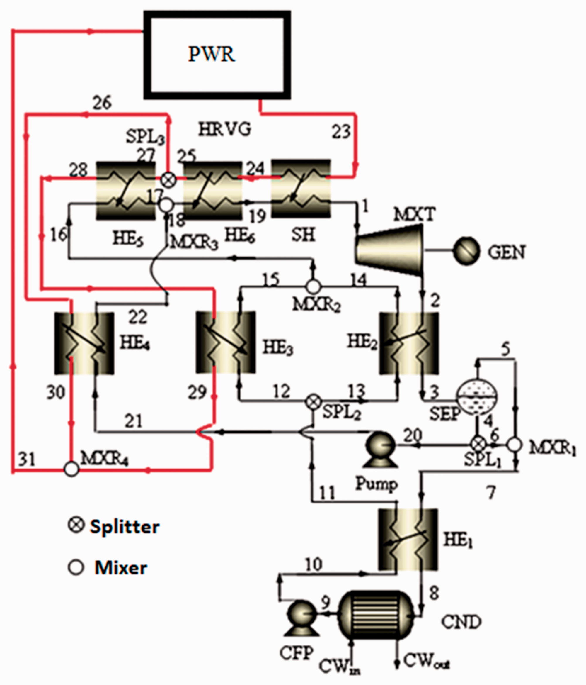
Schematic flow diagram of the Kalina cycle MTKCS with nuclear reactor as external boiling unit.
Kalina cycle (KC) efficiency
21

Kalina cycle exergy efficiency
21

The assumptions for the analysis of the two systems are tabulated in Table 2.
Assumptions used in the thermodynamic analysis.

Kalina cycle relative efficiency

Results and discussion
The simulated results relating to power and efficiency of turbo machines developed for the two KCSs are discussed below.
Figure 4(a) to (c) depicts the enthalpy–entropy, temperature–enthalpy and temperature-specific exergy diagrams for the MTKCS. Figure 5(a) and (b) shows the variations in specific power with separator temperature and turbine concentration for both systems. Separator temperatures were simulated in the range of 110°C to 155°C for the LTKCS and 70°C to 100°C for the MTKCS. Turbine concentration ranged from 0.85 to 0.97 for the LTKCS and 0.77 to 0.86 for the MTKCS. As we are nearing global depletion of conventional fuels, the two systems have been modelled with an unconventional heat supply system. The specific power increases from 60 kW to 130 kW for the LTKCS with an increase in the separator temperature from 110°C to 150°C. For the MTKCS, the specific power decreases from 267 kW to 240 kW as the temperature is increased. The high pressure in the cycle is a function of separator temperature and turbine concentration. The liquid concentration in the separator is directly proportional to the pressure. To match the bubble point and separator temperature, the liquid concentration must be increased. These changes cause the mass flow to the turbine to decrease. The combined effect of decreased mass flow and increased high pressure causes the turbine work to increase by a small amount resulting in increased specific work. For the MTKCS, the liquid concentration in the separator decreases with increased separator temperature at constant pressure. The turbine mass flow rate also decreases, as it is directly proportional to the liquid concentration in the separator. The dew point temperature remains constant, resulting in reduced output. The trends are identical for both the separator temperature and turbine concentration. An optimal value for the specific work of the MTKCS is achieved with the parametric change in turbine concentration.
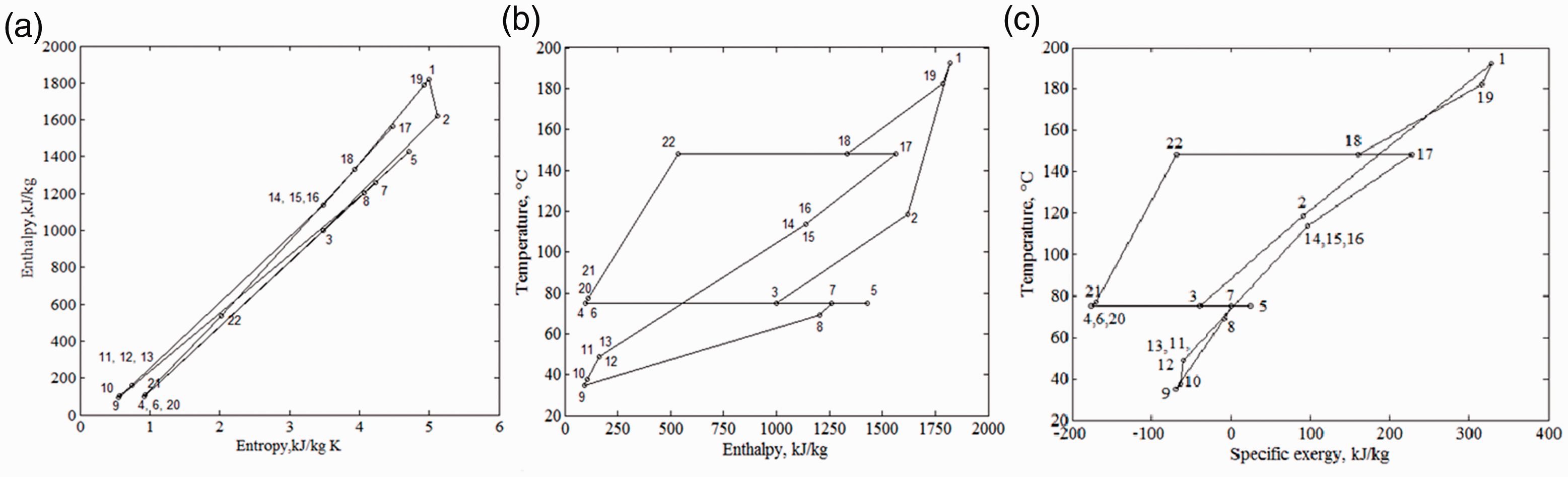
(a) MTKCS Enthalpy-entropy diagram, (b) MTKCS Temperature-enthalpy diagram and (c) MTKCS Temperature-specific exergy diagram.
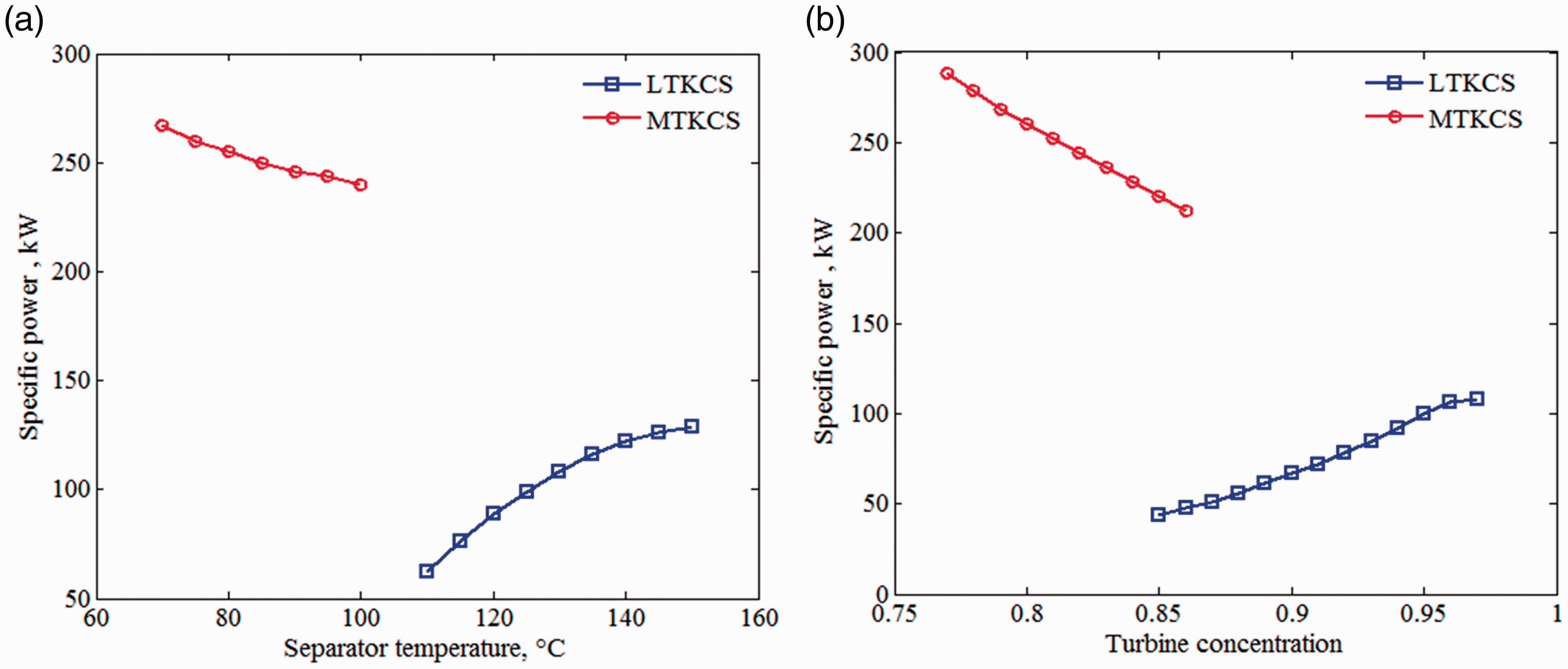
Influence of (a) separator temperature and (b) turbine concentration on specific power for LTKCS and MTKCS.
Figure 6(a) and (b) shows the variations in cycle energy efficiency with parametric variations in separator temperature and turbine concentration. The cycle energy increases from 5.15% to 12% for the LTKCS with the increase in separator temperature, whereas it decreases from 19.25% to 13.8% for the MTKCS. The cycle energy increases from 3% to 10.1% for the LTKCS with an increase in turbine concentration, whereas it decreases from 20.8% to 14.3% for the MTKCS. With an increase in separator temperature, the high pressure increases significantly, and the low pressure increases slightly for both systems. The increased pressure causes the turbine expansion to also increase. With a decrease in the heat load at the evaporator the efficiency increases and the heat supplied to the boiler decreases. As a result, the efficiency increases. At increased turbine concentration, with fixed high pressure, the dew point temperature decreases, favouring a decreased supply temperature. Turbine concentration is inversely proportional to the mass flow rate at the turbine. With an increase in turbine concentration, the mass flow rate to the turbine decreases. The heat load at HE3 increases with decreased heat load at HE2, resulting in decreased efficiency.

Influence of (a) separator temperature and (b) turbine concentration on cycle energy efficiency for LTKCS and MTKCS.
Figure 7(a) and (b) shows the variations in relative efficiency with changes in the separator temperature and turbine concentration parameters. The relative efficiency increases from 24% to 56% for the LTKCS with an increase in separator temperature, whereas it decreases from 57% to 41% for the MTKCS. The relative efficiency increases from 14% to 47% for the LTKCS with an increase in turbine concentration but decreases from 62% to 42% for the MTKCS.
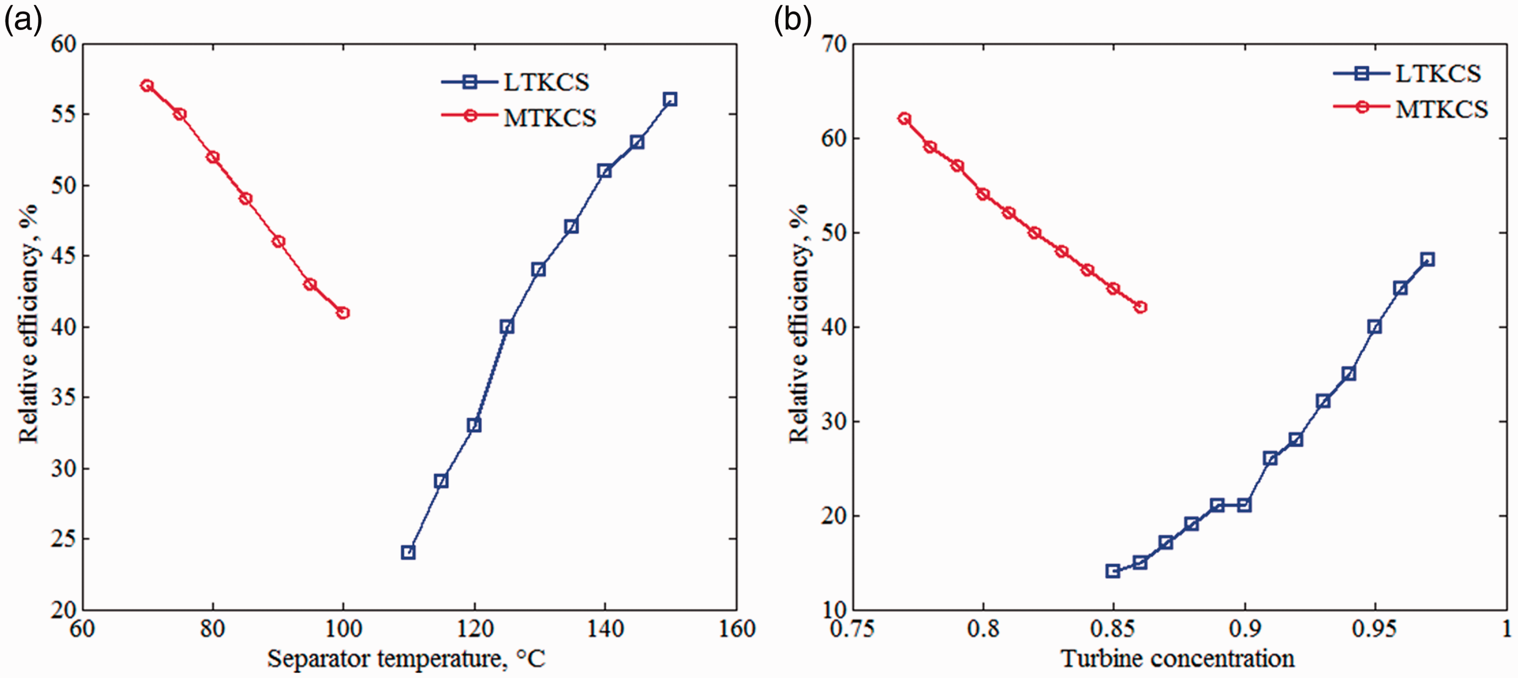
Influence of (a) separator temperature and (b) turbine concentration on relative efficiency for LTKCS and MTKCS.
Figure 8(a) and (b) shows the variations in exergy efficiency with changes in parameters separator temperature and turbine concentration. The exergy efficiency increases from 53% to 72% for the LTKCS with an increase in separator temperature, whereas it decreases from 78.5% to 62.7% for the MTKCS. The exergy efficiency increases from 37% to 71% for the LTKCS with an increase in turbine concentration but decreases from 80.5% to 67% for MTKCS.
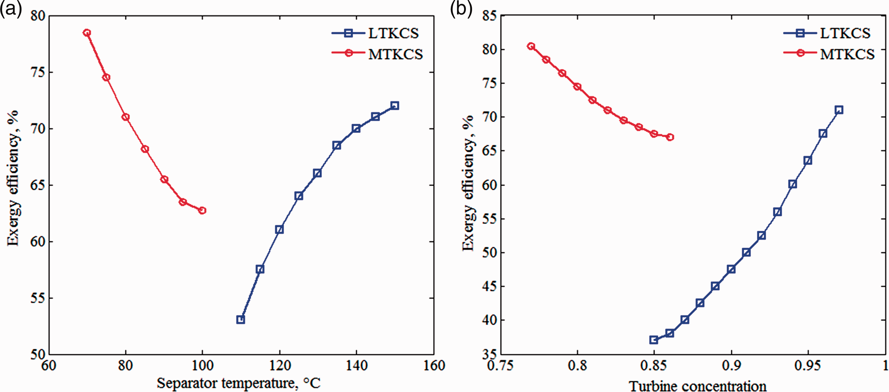
Influence of (a) separator temperature and (b) turbine concentration on exergy efficiency for LTKCS and MTKCS.
Table 3 gives the details of the working fluid and hot source fluid at the state points, defined in Figure 2. The results are plotted at a separator temperature of 125°C, strong solution concentration of 0.77, 1 kg/s of working fluid and turbine concentration of 0.95. The specific enthalpy value is higher at high input conditions (state 1). The value proves to be lower at condenser outlet conditions. The dryness fraction for a vapour is 1 and for liquid is 0, hence states 1 and 10 are in vapour conditions. States 5–9 and states 12–13 remain in liquid conditions. The entire system is solved with a unit mass of working fluid at the turbine which consumes 3.80 kg/s of hot source fluid.
LTKCS material flow details with respect to Figure 2 at Indian atmospheric conditions and Tsep = 125°C.

Table 4 shows the properties of the working fluid and hot fluid at the state points, defined in Figure 3. The results are plotted at a separator temperature of 70°C, strong solution concentration of 0.9, 1 kg/s of strong solution and a turbine concentration of 0.8 at 50 bar. This results in a hot fluid inlet temperature of 217°C. A unit mass of working fluid in the power circuit demands 3.58 units of hot water under the above conditions. The unknown properties at the state points are determined from the equations outlined in the thermodynamic model. The turbine inlet mass flow rate is raised to 1.29 kg/s at the specified conditions.
MTKCS material flow details with respect to Figure 3 at Tsep = 70°C, strong solution concentration of 0.90 and turbine condition of 50 bar and 0.80 concentration.

The present thermodynamic evaluation for LTKCS has been validated by comparing the existing Kalina cycle power plant located in Husavik, Iceland, running from hot water (geo thermal resource). Table 5 presents the comparative results of the current model and the running plant readings. 31 The plant is studied with the working conditions, i.e. at strong solution concentration = 0.81, T15 = 125°C, x1 = 0.95 and t5 = 12°C. Most of the calculated results in this work closely match the Husavik power plant conditions. The resulted low pressure is 5.4 bar against the 5.5 bar of the plant reading.35 These results have been matched with the results reported by Usvika et al. who reported 11.62% of energy net efficiency. For MTKCS, the present thermodynamic simulated results have been compared with the literature readings of Kalina power plant running from hot water of geo thermal resource. 30 The plant and current model are solved at strong solution concentration, x9 = 0.90 and T1 = 192°C. For condenser, the cooling water inlet temperature is considered as 16°C as per the plant data. Therefore, at the inlet of pump the resulted working fluid temperature is 21°C. Most of the calculated results are closely matched with the plant conditions. The resulted low pressure is 7.7 bar whereas 8 bar in the plant reading.
Comparison of the current series heaters plant results with the existing Husavik plant readings at 75% turbine efficiency (Tsep = 125°C and x1 = 0.95) for LTKCS and of the operational conditions of current work with the reported readings at 70°C separator temperature 30 for MTKCS.

Conclusions
The ammonia–water mixture properties calculated here using MATLAB give us an indication of the behaviour of this working fluid at a wide range of pressures and temperatures. Kalina cycle system is the best competitor to ORC. The cycle utilizes solar collectors, conventional boilers, nuclear reactors to generate binary vapor. The cycle using nuclear reactor to generate steam will work with single component environment friendly working fluid. In the present work, low temperature Kalina cycle system and medium temperature Kalina cycle system have been investigated at various separator temperatures and turbine concentrations. The two KCS have been examined with hot source from solar and nuclear. Both frameworks can be used in either system, though because of pressure limitations we assume the medium-temperature KCS uses the atomic source. The LTKCS provides its highest performance at an optimised separator temperature of 150°C and turbine concentration of 0.97. The MTKCS achieves its highest performance at an optimised separator temperature of 100°C and turbine concentration of 0.87. The sink temperature in Indian climatic conditions is approximately 25°C. The output of the MTKCS is higher compared to the common Kalina cycle configurations. The mass flow rate to the turbine inlet of the MTKCS is increased with the cycle configuration and hence results in increased performance but without affecting condenser performance. Hot fluid of 3.58 units at the separator temperature has resulted with unit mass of strong solution at the separator temperature of 70°C for MTKCS, whereas 3. 8 units of hot fluid at the separator temperature have resulted with unit mass of strong solution at the separator temperature of 125°C for LTKCS. In LTKCS, the separator is located before turbine and hence requires high separator temperature. The total cost of the Kalina cycle of 2 kW capacities suitable for low temperature applications will be around 16,00,000 rupees. Based on the development of heat exchangers and with increment in quantity, the cost varies.