



Abstract
To address the future growth in energy demands, complete renewable power generation from environmental assets demands unique methodologies from every investigator. Wind energy harvesting in residential areas is one such approach. But the urban landscape and the physical challenges restrict the erection of small-scale wind turbines. Further, a significant degree of uncertainty leads to a lack of awareness of how dispersion in urban environments impacts turbine performance. This research looks into the potential productivity of wind turbine installations in urban areas, considering turbulence. These unique ambient conditions prevailing in a dynamic environment compared to flat terrains have made the harnessing of wind energy very difficult. Many researchers are still trying to find an effective methodology in these constrained circumstances. Since the characteristics of small-scale wind turbine models are undetermined, large-scale turbines fared well compared to small-scale wind turbine models. The feasibility and success of small and medium turbines in community homes were investigated in this study. The origins of the very uncertain nature of atmospheric boundary layer limitations are discussed in this work and subsequent successful developments by different researchers.
Introduction
Globally, the search for alternative energy sources is being propelled by the global energy crisis and the inability of traditional power to fulfill demand. 1 Because of its long-term viability, renewable energy sources have piqued the world's interest Wind energy is now cost-competitive with conventional power plants. 2 The power-producing capability of wind turbines is classified based on the rotor diameter are illustrated in Figure 1. Large-scale wind turbines can produce 1 to 3 megawatts of power and have rotor diameters ranging from 50 meters to 100 meters. Small-scale wind turbines are defined as those having a rotor diameter of 3 to 10 meters and a power output of 1.4 to 20 kW. Tummala et al. 3 classified the small-scale turbines into the micro level, mini level, and small-scale household turbines capable of generating 0.25 kW, 1.4 kW, and 16 kW, respectively. They stated that small-scale wind turbines are more efficient under optimized conditions with a low-cost design. 4 James et al. 5 classified the small-scale turbines into lattice towers, vertical axis, pole-mounted, and building-mounted types. They proposed that the building-mounted turbines can produce a maximum of 1.4 kW which can be utilized for battery charging applications. In general, small-scale wind turbines possess a tower-mounted structure capable of producing a minimum of 1.5 kW. Horizontal axis wind turbines with three blades are particularly popular because they strike a better balance between cost and efficiency. According to an earlier study, more blades can produce higher output, such as an infinite no of blades, which can achieve 59.9% efficiency, but the cost of production and operation must be considered. 6
However, due to the high capital cost of grid connectivity, small-scale turbines are often not favored. Table 1 summarizes the performance through many small wind turbines with a horizontal-axis wind layout.3–12 and vertical axis wind turbines in Table 2.13–16 Rooftop turbines, small-scale wind turbines, testing methods, as well as how to improve performance will be discussed in subsequent parts. This study provides novel information on the features of focusing on the rooftop turbines model. The model of turbines we examined could be adaptable and capable of functioning in adverse situations. We conducted a collective analysis of turbines in urban locations and considered the several options for operating them as efficiently as open-field turbines. Furthermore, the investigators have had difficulty electricity generating in an urbanized area because of the unpredictable wind flow. Turbine aerodynamics, blade substances, models, extensive simulation techniques, performance validation, grid integration, and environmental issues have all drawn tremendous attention. This manuscript focuses on new concepts for wind turbines in urban areas. We also looked into the factors that help to reduce the amount of uncertainty in the urban environment. Frequent obstructions, quick changes in the wind flow direction, and ground roughness have all been identified as major causes of wind turbine inefficiency in urban areas. We suggest a technology in this paper that can gather wind at greater elevations while remaining operational at ground level. Even in the face of difficulties, the manuscript highlights the need for increasing wind speed in urban environments. It provides a path for young scholars interested in new dimensions of thinking.
Performance of small scale horizontal axis wind turbines.
3
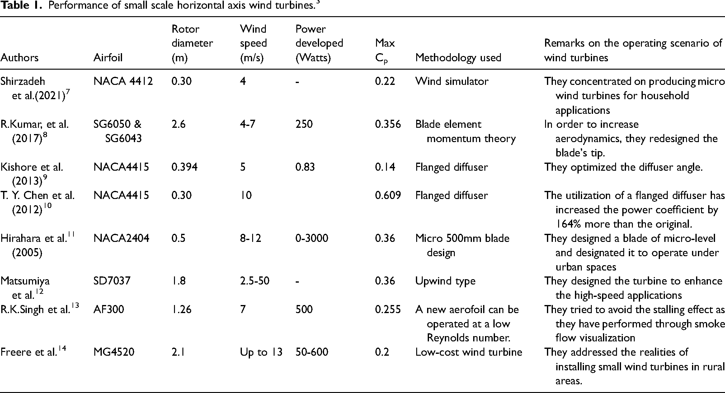
Performance of small scale horizontal axis wind turbines. 3
Performance of small scale vertical axis wind turbines. 3

Nalanie Mithraratne 17 deployed a microgrid in individual buildings, contributing to New Zealand power generation. He identified that the main drawback in such systems lies in their non-competence in all areas. Also, the power generated can satisfy only a small portion of the requirement. As a strategy for creating a more sustainable environment, rooftop turbines can be used to power tiny homes. But still, the potential of the centralized large-scale wind farms is far better when compared to the decentralized small-scale farms. The research concluded that the rooftops in the present form are not suitable for meeting the demand of an entire individual house. Islam Abohela et al. 18 described how the wind flow influences the proximity of the rooftop wind turbines. They investigated various shapes, directions, surrounding conditions, and the height of the turbine location. Also, they demonstrated the effectiveness of various roof profiles influenced by flow disorders, patterns, and intensities. 19 They identified that the turbulence intensities are high on roofs and the roof shapes directly influenced the acceleration. On the high-rise or isolated buildings, the turbines can be mounted on roofs which cannot be implemented in low-rise buildings. There must be at least 1.3 times all those turbines as high as the building to get acceleration effects. 20 Rohan Hakimi et al. 21 reported that the obstacles parallel to the roof impacted the wind speed with high turbulence intensity. The research established that the trees around the turbine-installed areas could generate a high level of uncertainty in the flow direction. 22 The rooftop turbines must be placed on the tallest building in that area to maximize the potential of the tower-mounted turbines. Also, the wind flow should be perpendicular to the roofline. 19 B. Wang et al. 23 examined the wind amplification under the roof canopy. The simulation results indicated an absence of wind amplification under a normal canopy roof. Hence, the research introduced a modified canopy with an overhanging structure. Despite its enhanced performance, the overhanging structure impacted the wind concentration. The mono-pitched and double-pitched canopies were validated. A venturi-shaped form with a streamlined body was proposed as an outcome of validation which gave a better amplification effect when compared to other configurations.
Qiang Wang et al. 24 computed the airflow over buildings in urban residential areas using lidar measurements. They validated the effect of turbulence, wind acceleration, and turbulence thickness on wind performance. The turbines mounted at a minimum elevation of 1.3 times the building height performed well, eradicating these highlighted issues. Further improvement was noticed when the turbine was placed at an elevation ranging between 1.51 and 1.79 times above the original height of the building at its front face. The presence of a shroud or diffuser improved the performance considerably. The flanged diffuser directed the flow towards the turbine in an up-surged manner which elevated the performance. The wind tunnel design under urban boundary conditions was generated and experimentally validated. The research concluded that the cycloid cross-sectional casing produced better acceleration than others. 25
Balduzzi et al. 26 examined the Darrieus upright axis wind turbine's viability for a populated area. The investigation characterized the flow fields on building rooftops using CFD analysis under upwind conditions in urban building environments as a pre-processor for an installation. Also, they evaluated the sloping roof configuration under the same constraints. The velocity contours for the various positions were calculated, and the assumptions were formulated using the Rayleigh distribution. Also, the impact of the skew angle on the power performance was calculated and optimized for enhanced functionality. With the newly prepared model, a feasibility analysis was done on various turbine sizes in the built environment. The research established that the turbine's performance on the rooftop increased by 70% compared to the turbines on the ground in an urban environment. 27
The performance increased further when the located building was reasonably higher than the surrounding constructions with optimized geometrical parameters. The sloping roof positively impacted wind velocities with a slope of the inclination angle of 8° compared to the flat roofs. The research also established the prevalence of optimal conditions under the Darrieus turbine implementation in urban environments up to 12% if the skew angle was maintained between 150 and 350. Wind turbines with a convergent-divergent wall were studied by Zanforlin et al. 28 in a two-dimensional CFD analysis. The investigation found that placing the wall parallel to the crest of the roofs resulted in a better level of efficiency than alternative placements. Also, a diffuser-shaped wall in the preceding zone of the dual pitched roof increased power in the range of 40 to 50% in ground-level turbines. The torque gained from this diffuser setup was identified by static pressure and velocity contour analysis in the flow fields over turbines. Under upwind flow conditions, the diffuser augmented and guided the flow towards the turbine blades compared to the downwind conditions where the diffuser augmented the absolute flow velocity. Wang et al. 29 examined the potential of vertical axis wind turbines (VAWT) in densely populated areas for generating electricity. The researchers investigated the dynamic responses of VAWT. The dynamic analysis was obtained by calculating the structural vibrations of the VAWT. They identified that the blade rotation speed produced increased vibrations. They traced the vibration responses using stochastic subspace identification (SSI). The results established the tower vibration of VAWT along with the load on the turbines. 30
Summary of approaches that can root efficient rooftop wind turbines in the urban environment
Several positive factors are identified from the literature despite the need to improve the rooftop turbine configuration as a part of the house in an urban environment. The collective suggestions17–26,31,32 for the enhanced problems and improvement of the wind turbines are listed in Figures 2 & 3 are described as follows. The rooftop turbines can be located at an elevation range of 1.51 to 1.79 times the building height above its top for better performance. 33 The multiple sequential turbines performed better when compared to the single turbines. Also, they exhibited enhanced improvement when located at the front face of the houses. The wind flow perpendicular to the roofline yielded maximum power. The inclined roof within an angle of 8° produced more power when compared to the canopy and flat roofs. The addition of a diffuser preceding the turbine blades augmented the velocity significantly. The cycloidal diffuser performed well when compared to the other shapes. The turbines located at the venturi section of the diffuser or throat section streamlined the wind flow optimally towards the blades with reduced turbulence.

Rotor diameter classification of various sized turbines. 3

Summary of problems in rooftop wind turbines in the urban environment.

Summary of improving performance for rooftop wind turbines.
A modest wind turbine's increased revolutions per minute (RPM) increased vibration. Power generated by rooftop turbines cannot meet the needs of any individual home. On the ground, the wind speed is mainly unstable and moderate at times due to increased turbulence in the urban region due to the thick atmospheric boundary layer and increased roughness. Turbine start-up and cut-in speed are major concerns when the wind speed is low. There are different criteria for small-scale wind turbines than for larger ones.
Performance measure of wind turbines in a populated area
Wind resource assessment in an urban environment
Reiter 34 suggested a simple design with enhanced comfort for urban designers. Gaussian, Weibull, and Rayleigh methods were used to gauge urban wind resources. 35 Some researchers prominently assessed the resources irrespective of changing the turbulent intensity by positioning the turbine 1.5 times above the median height.. 36 The probability functions of Weibull and Rayleigh have shown good effectiveness in coastal areas and open field applications. 37 Moreover, attempts were made by Mathew et al. 38 to identify the optimal resource among the available resources. But the outcomes lacked accuracy in a populated and high-density environment. Micropower generation is mostly suitable when compared to large-scale applications, as indicated by the wind resource assessment in urban areas. 39 The direct field measurement and wind tunnel experimentation are effective despite the problems of cost investment, time consumption, dynamic similarity, and blockage factors. These factors have made the researchers work in computational fluid dynamics to improve turbine efficiency.40,41 The exposure of micro energy applications to urban environments involving complex modeling was formulated by researchers recently. Cheng et al. 42 investigated the effects of flow fields over different layers and analyzed the roughness effects of the turbine in a complicated scenario. The investigation identified the impossibility of the replication boundary layers with roughness factors for wind tunnel testing. Heath et al. 43 determined the numerical proportions of the wind speed over urban buildings. The research stated that the type of roof structure considered for experimentation was performed equivalently with the standard configurations. The developed results were accurate when compared to the wind tunnel experimentation. 44
Despite all negativity, further efforts were initiated in implementing wind turbines in an urban environment Lin Lu et al. 45 investigated three configurations having dimensions of 25 m X 70 m X 25 m each on two identical buildings. They identified that the building's concave, convex arc and hemisphere shapes augmented the velocity at a considerable pace. Ledo et al. 46 studied theimpact of roof profiles on wind turbine performance. Three profiles of different shape flat configurations were considered, outperforming the pitched and pyramidal roofs. Wang et al. 47 analyzed the energy potential between two perpendicular buildings over their roofs. The wind tunnel experimentation was conducted to validate the results as a pre-processor for the CFD analysis. The results indicated that the converging inlet angle of 45° performed better when compared to the other inlet angles. 48 Sari et al. 49 studied the roof pitch angle influencing the power output. The study established that an angle of 30° enabled maximum power density. Reiter 34 planted a town-down plan for the wind mitigated zones in populated areas, stressing human safety. The validation of the experimental and wind tunnel testing error rate is high despite shape optimization in the performance improvement of wind turbines. 50 Al-Quraan et al. 39 established a link between the wind tunnel's accuracy and the difficulty of the terrain. The investigation was validated under both homogenous and non-homogenous terrain conditions. The measurement error ranged up to 5% on ideal or less complex terrain conditions. But the error rate increased to 17% in non-homogeneous terrains due to the atmospheric boundary layer. 51
The urban environment's atmospheric boundary layer
To assess the impact of the urban boundary, we measured wind speeds in the same locations but at various residential areas in Table 3. The results show a maximum wind variable speed of 66.6%. Various authors describe the impacts are listed as follows. In the built environments, the atmospheric boundary layer is complicated and results in a rough diverse landscape.. 52 The development of multiple terrain layers inside the boundary layer keeps the level of uncertainty at a high phase. 53 Kabir et al. 54 established that the turbulence level of the atmospheric boundary layer impacts the velocity and the wake aerodynamics adversely. The wake recovery rate and ground effects on velocity degradation are higher due to higher turbulence levels on the atmospheric boundary layer than the turbines located on flat terrains. 55 They suggested that the installation of small-scale wind farms will induce conducive atmospheric boundary layers, which will play a vital role in velocity and wake recovery.56,57
Summary of wind resources assessment in urban environments.
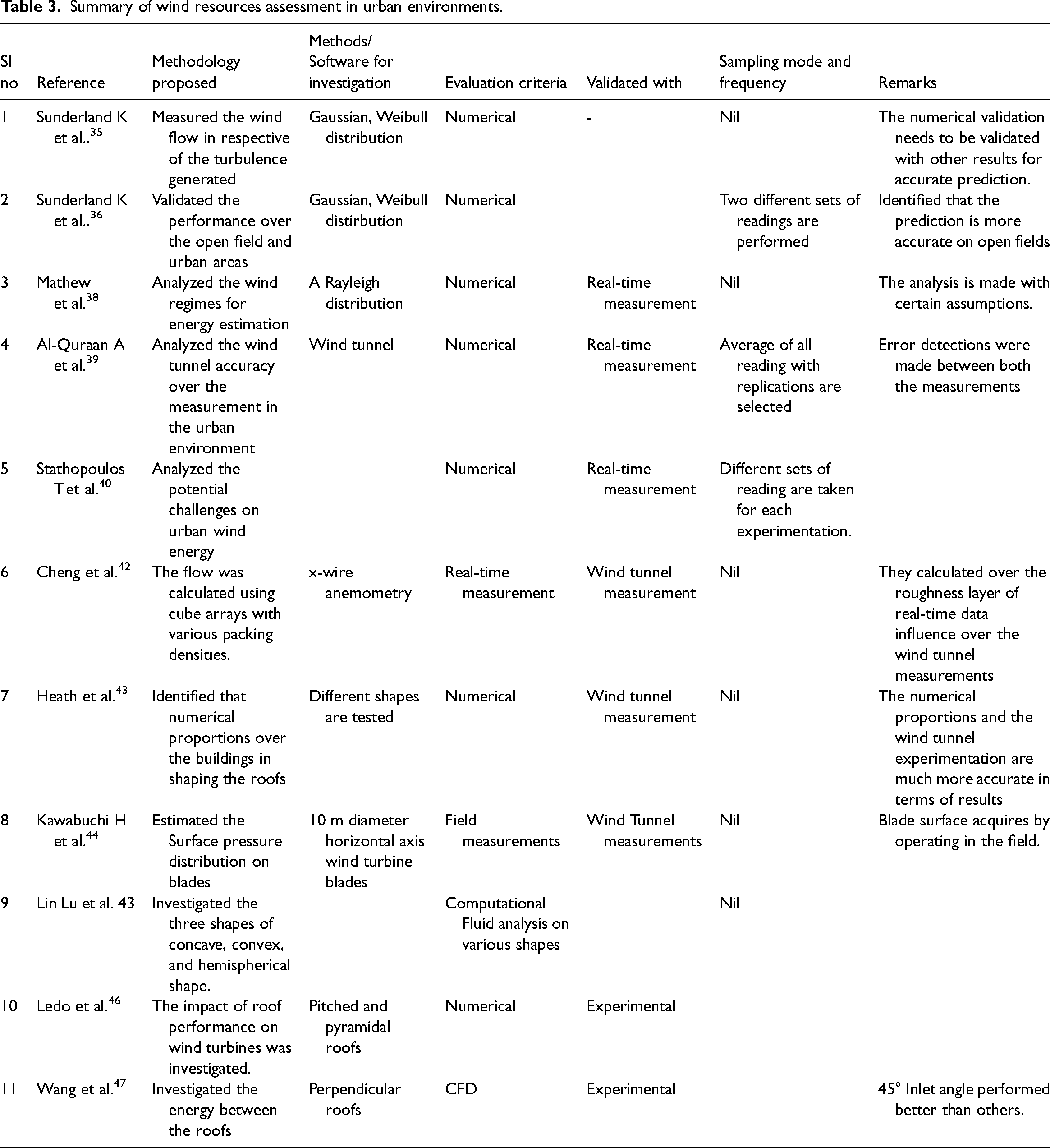
Summary of wind resources assessment in urban environments.
In preventing the uncertainty of wind flow, a comprehensive wind flow assessment in urban settings is a no-go. Such efforts are discussed in the current section are summarized and presented in Table 3. Even though many researchers have worked on estimating wind, there is still room for improvement in the precise replication of field observations without assumptions.
Issues impacting small-scale turbine performance in urban areas
The research is being carried out to run a wind turbine in Indian conditions. Savitha Lolla et al. 58 evaluated wind potential in five different Indian regional circumstances, claiming that when compared to other regions in India, southern regions are better appropriate for turbine installation due to superior grid connectivity. In particular, Kulkarni et al. 59 found suitable places for large-scale power generation in the southern regions. Biao et al. 60 examined wind flows in distinct open fields and built environments to investigate wind flow at wind locations. Although wind velocity in vast fields is typically higher than in cities, turbine installation in residential areas is restricted due to agricultural land use.
Further, the researchers explored the morphological characteristics of the building layout and its impact on wind flow. The building layout impacted the wind velocity significantly for the turbines installed in an urban environment. 1 There were negative connections found between the drag and the layouts, as well as the spatial average velocity and the layouts for sustaining the turbines in an urban residential setting. 19
Anup K.C et al. 61 reviewed the wind flow in small-scale wind turbines in an urban residential environment. The research analyzed and defined the stochastic nature of wind flow in a populated environment and its impact due to frequent obstacles. Extensive research was done to identify suitable standards for facilitating wind turbines in the built environment. 20 The researchers also indicated that the turbulence of flow impacted the energy and longevity of turbines. 62 The sudden inclusion of external sources enhanced or degraded the flow. The higher turbulence intensity resulted in the degradation in power output, which is lessened by adding a diffuser setup. 28 The existing standard is generated based on the turbines operating in flat and open terrains. The main issue reported in the current standards reveals a non-gaussian environment where the wind flow is uncertain. This is simply because they are unsuitable for small-scale turbines operating in residential areas.. 63 The literature indicates that the turbulence intensity on turbines used in urban conditions is more when compared to the turbines operated on flat terrains. Researchers have identified the following conducive parameters in the operation of small-scale turbines in urban residential environments with the help of numerical and scholastic modeling. The parameters are the inclusion of diffusers augments the performance of turbines. Significantly, the curved and spherical-shaped profiles increase the performance by 1.5 times more than actual profiles with reduced turbulence. 64 The location of the turbines at 50% above the roof height eradicated the turbulence. 65 According to the simulation findings, the K-Epsilon turbulence model outperformed the other models.. 66 A new approach was carried out by Karthikeyan et al. 67 for operating the turbines under a Reynolds number within the range of 500,000. The research summarized various results from the literature, which included the modification of the trailing edge and camber line of the aerofoils. 68 The researchers identified that the aerofoils with the thinner trailing edge and the curved surface increased the lift and drag ratio and reduced the noise by 5 decibels. 69 Similarly, the flatback trailing edge produced good structural stability, with reduced material cost, and initiated the turbines in advancement compared to the traditional turbines. The modification of thin aerofoils with shorter chord lengths increased the performance of turbines with reduced weight. 70 The conditions are highly uncertain and not favorable for installing wind turbines in all regions due to the requirement of huge areas. Moreover, the urban residential conditions pose various hurdles to the turbine establishment. The turbulence generated due to the obstacles has significantly affected the performance and potential of the small-scale turbines. 71 Much research is done on mounting the turbines on the rooftop to eradicate the mentioned hurdles. But the procedure still requires optimal design and positioning. To lessen the disorderliness in the flow toward the turbine, a fluid flow study is carried out. When compared to the 2-dimensional validation, the 2.5-dimensional and 3-dimensional models produce more exact and accurate results. The noise generated during the turbine operation is reduced by thickening the trailing edge and the tail shapes. Also, the flatback trailing edge produced good structural stability. 72 The ratio of aerodynamic torque to the rotational inertia of the blades determines the rotor speed in wind turbines. Generally, small-scale wind turbines require aerodynamic torque for starting. 73 The blade weight and inertia reduction can further reduce the starting time despite its independence of the number of blades. 74 The microturbines usually start rotating in quick succession as they commence at a high starting torque. But due to their high inertia, it takes a long time to generate power. Wind turbines operating under low Reynolds numbers is a point of concern as it requires a very thin aerofoil setup. 75 Table 4 summarises the challenges with small-scale wind turbines in urban areas.
Summary of issues for a wind turbine in urban environments.
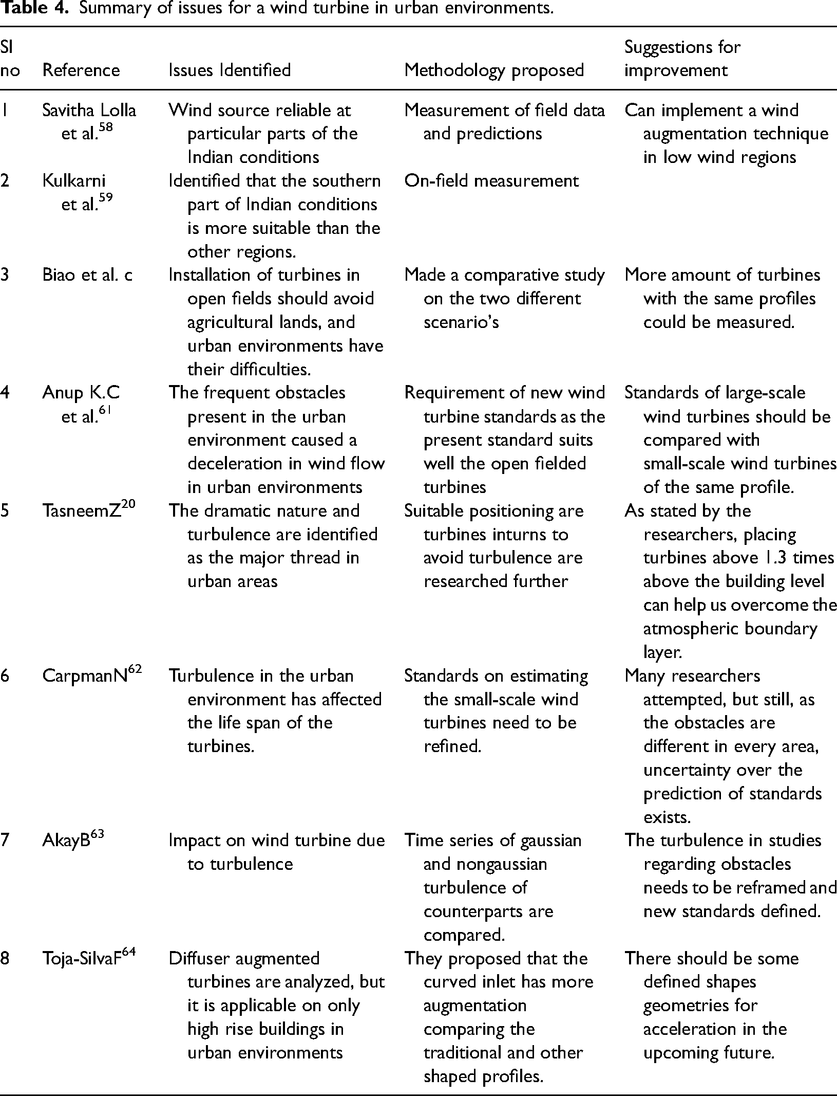
Summary of issues for a wind turbine in urban environments.
Low wind flow in urban regions than rural and sub-rural areas
In India, 90% of wind power development comes from six states. Statistical analysis in these states indicated the scope for growth in power production. 76 Sixteen exploratory factors influence wind power. The present policy is not suited for future development.77,78 Kumar et al. 76 stressed the importance of the economics behind the wind turbine installation and the design factors. The wind system conditions in India are satisfactory, according to the author. In recent years, there have been encouraging signs of progress. Rooftop and offshore wind farms, on the other hand, require a great deal of work.79,80 They listed that many technological modifications need to be made on the wind turbine to enhance its functionality in unfavorable conditions, establish accuracy in wind measurement, manufacture with local bodies, and robust transportation.41,81 Kulkarni et al. 82 analyzed the impact of climatic changes on wind persistence in Indian offshore conditions. The research identified four significant locations and was validated using different techniques. Among the techniques, the wind speed duration curve proved to be optimal as it also presented the physical interpretation of results. 83 Fiedler et al. 84 performed an analysis of the climatic change due to wind farms. They suggested that the small and large wind farm's effect on the climate was negligible. Wang et al. 71 described that using a wind farm will facilitate an increase of 1 ° C in inland areas and a proportionate reduction of 1 ° C in the sea areas. They can also influence the rainfall during the rainy seasons.
Wake generation in small scale wind turbines
One of the main causes of low wind speeds in urbanization is the wake expansion behind the rotor. The researchers employed dye visualization and particle image velocimetry to propagate the wake expansion.85,86 The results revealed that the wake expansion proportionately rises because of the blockage, causing a reduction in performance. 87 But the wake expansion was the same for the blockage effects, which lie within 0 to 10%. Also, the researchers varied the Reynolds number in small-scale turbines. Two scale horizontal axis turbines were used inside a closed water channel with the Reynolds numbers ranging between 3620 and 31,400. They identified that the wake generation and the thrust coefficient differed for the two different scaled models.86,88 Santhanagopalan et al. 89 coupled the Reynolds’s averaged Navier strokes (RANS) with dynamic programming to enable wind turbines’ optimal functioning. With the mixing length model, they predicted wake generation and power production while taking into account the tip speed ratio and inflow turbulence..90,91 The approximations of the parabolic and boundary layer models produced good results. However, the accuracy of estimating wind speed was influenced by approximations and estimates of turbulent length.92,93
Turbulence on residential areas affecting the performance of the small-scale turbine
A study of the turbulence effect on wind turbines with a horizontal axis employed wind tunnel tests. Wind tunnel investigations have shown that turbulence has a negligible impact on thrust and power. 88 The turbulence level had made a significant influence when the angle of attack was greater than 12°. Loganathan et al. 94 found that pressure gradient harms the development of Savionous micro wind turbines The multi-bladed rotor's power production decreased as turbulence intensity increased. The investigation also found that input velocity had a greater impact on power production than turbulence intensity. Wafula et al. 95 investigated the aerodynamical performance inside a closed wind tunnel by considering the changes in turbulence intensity. They generated the turbulence inside the closed wind tunnel using elliptic wedge generators. 96 The experimental results were validated with the standard numerical data. The experimental results indicated the dual nature of the turbulent intensity on small-scale turbines. When compared to the uniform flow, the wedge-generated turbulence flow produced greater power. When the speed improved 7 m/s, it decreased dramatically. 97 On small-scale wind turbines, the turbulence improved the performance under low wind speeds. At high wind speeds, an adverse impact was visible. A lot of consideration was given to blades for withstanding the increased aerodynamic loads despite a positive effect under low-speed conditions. 98
Effect on standard on small scale wind turbines
Evans et al. 99 provide an assessment of the quality of their work on a 5kW horizontal axis wind turbine. They gathered information in densely populated areas and on flat terrain. Using the International Electrotechnical Commission's (IEC) 61400-2 standard to compare the data. The longitudinal turbulence intensity was found to be greater than the expected value in a populated area but lower in a flat terrain environment. 100 Increased turbulence in densely populated places has resulted in more electricity than expected while also increasing the load on the turbine blades. The present IEC standard is built on flat terrain, making it ideal for examining small-scale wind turbines in densely populated areas. 101
Effect of noise on small scale wind turbines
Noise pollution is one of the major downsides of small-scale wind turbines when it comes to developing wind turbine technology in urban areas, according to report. 102 It creates further concern as they are located near populated areas. The investigators proposed a new numerical optimization approach called 'differential evolution' to reduce noise without affecting power production. The optimization approach coupled the empirical noise prediction model and the blade element momentum theory for forecasting the power output. 103 The differential evolution results indicated that reducing the power coefficient by 1% can reduce the sound level by 2 dBA. For a tip speed ratio of 5.5, the sound level was further decreased by lowering the angle of attack or expanding the Reynolds number. Further improvement in noise level reduction was achieved by reducing the start time with the same features as a part of future development. 104
Summary of dependency of issues in wind turbines on a small scale in residential areas
The interconnection of difficulties relating to small-scale wind turbines complicates the process of resolving limits and mitigating concerns in the built-up environment. Figure 4 summarises the issues linked with small-scale wind turbines in urban areas. The singular flow represents the parameter governing the variant, and doubleheaders are employed to illustrate the dependency of both processes. The large arrow lines indicate that the variables will significantly impact parameters.

Summary of dependency of issues in small scale wind turbines in urban residential environments.
Conventional wind turbines performance in the urban environment
Sunderland et al. 36 discussed the difficulties of placing small-scale wind turbines in urban areas. They presented two distinct models for estimating turbulence over a 2.5 kW turbine. The Gaussian technique is a probability function used to predict the wind speed, and it helps us associate consequences caused by turbulence. However, this model is the least accurate at higher wind speeds since it relies on a precise turbine power curve. The researchers avoided these common problems by using the Weibull distribution's probabilistic technique. Ernesto Arteaga-Lopez et al. 105 investigated an approach for harvesting the maximum wind power in an urban residential environment using small-scale wind turbines. They validated both the building shapes and wind turbines under urban boundary conditions. The multiple positioning of turbines was validated using the CFD software for accurate results. The turbine mounting on roofs gave enhanced performance and functionality, which was evident from the obtained results. Multiple turbines can be located sequentially on roofs to improve power generation and fulfil individual houses’ power demand.
Concentrator type lens augmented wind turbine
Pambudi et al. 6 examined the effect of installing a nozzle lens in front of the turbine. They used an artificial structure to analyze the turbine's concert at low wind speeds. The results suggested that including the lens increased the output power. The primary conclusion drawn from the experiments is that the diameter of the lens was related to the rotor speed and the tip speed ratio. Additionally, the three blades were more efficient and balanced than the other blade configurations. 106 Shonhiwa et al. 107 provided an overview of the concentrator-augmented wind turbine perception. They discovered that the concentrator increased the efficiency of the turbine by utilizing upstream wind. Also, the concentrator enabled maximum efficiency when it was located within 5 cm of turbine. 108 Though it suits the low wind regions, the wake effects need to be addressed for enhanced power output. Besides that, the wall length of the concentrator and the incident angle should be optimized for eradicating the frictional losses. 109 The significant advantage is its ability to target the wind velocity, which is the most dominant parameter influencing the power production. The outcome of the concentrator is calculated using the continuity equation. The research established that the performance of the turbine was better when the rotor diameter was larger than the concentrator outlet.
Shrouded – diffuser type ducting augmentation
Kosasih et al. 110 revealed small wind turbines in the built environment can be improved practically. Different diffuser forms and geometries were examined. It was determined that a straight-shaped diffuser, one connected to the nozzle by an arm, and one with an arm curled around it were the best candidates for this research. The brimmed diffuser's performance was compared to that of the bare augmented turbine in the study. Diffuser length and projection height were studied for their effects. The results indicated an optimal performance of 60% and 63% for the diffusers of the bare turbines with shroud and the diffusers with nozzle, respectively. The performance was primarily influenced by the difference in the tip speed ratio. At the same time, it was independent of the length of the diffuser. 25 The inclusion of the flange at the exit increased the performance further. The development of different shaped diffusers over the years by ohya et al..111,112 Are illustrated in Figure 5.

Khamlaj et al. 106 revealed that the wind lens turbines performed better when compared to the unshrouded turbines and bare turbines in a residential environment. Usually, the wind lenses are designed as the diffuser type. Also, a flange was added at the exit to eradicate the back pressure. 110 Optimization was accomplished through the application of a genetic algorithm defining the diffuser's geometry and flange height. They designed the Bezier curves for the geometric features of the turbine blades. Also, the diffuser shape was represented using a quadratic piecewise polynomial. The researchers validated the model using Reynold's averaged Navier strokes equation with the K-epsilon turbulence model. 113 The grid convergence approach increased accuracy and precision for validating the lens shape. The results indicated a better power coefficient for optimal design.
Kishore et al. 9 created a small-scale wind portable turbine (SWEPT) capable of functioning at speeds less than 5 meters per second. It generated 0.83 watts of power at a wind speed of 5 m/s. Experiments in the wind tunnel revealed a maximum power coefficient of 0.14 at a tip speed of 2.9. The researchers validated the wind speed augmentation convergent and diverging parts. According to the computational fluid dynamics studies, the diverging part had a greater effect on performance than the converging section. According to the research, the diffuser converging section should be 0.125 times the throat diameter in length and have a cone angle of 15°. Similarly, with a cone angle of 10°, the diverging section length was defined to be the same as the throat diameter. The ideal configuration of diffuser-augmented turbines generated 1.4–1.6 times the power of a turbine without a diffuser. When compared to large-scale wind turbines with the same profile, small-scale wind turbines display significantly different aerodynamic performance. Additionally, because small-scale wind turbines are usually used in low Reynolds number applications, the airfoils selection is critical.
Increased velocity using the omnidirectional (INVELOX) 114 system is unconventional for wind turbines inside the living environment. Having the INVELOX as an additional setup for standard turbines has justified the concept of wind turbines. It also overcomes the enormous barriers faced by traditional turbines in residential areas. The generator setup speed augmentation depends on the turbine size since the INVELOX design separates the wind collecting area and the turbine. The turbine is also able to operate at the surface of the ground, which diminishes operative and turbine preservation costs. The emergence of small blades to operate at higher speeds reduces the manufacturing cost of the blades by 85% when compared to the traditional turbine blades. Also with INVELOX, yaw control is abandoned when rotating the turbine in a prevailing wind motion. Also, it increases the amount of wind meeting the turbine. The maximum wind speed on the INVELOX is identified at the venturi section, where it doubles the speed at the inlet. The flow pattern inside the INVELOX is analyzed through the computational fluid dynamics (CFD) software. The flow pattern is not the same in the various sections of the INVELOX. Three collection methods are evaluated to boost the flow of material toward the turbine. Among them, the top layer tilted at an angle of 45° facilitates better results than the combined layer of the INVELOX and the partitioned INVELOX. The speed ratio of the INVELOX ranged between 1.5 to 2.1. The INVELOX heavily depends on the wind direction despite the omnidirectional nature of the intake due to the obstacles present in the living environment. 115 The omnidirectional intake possessed issues, including the wake generation towards the turbine due to the freestream of wind flow inside the duct. Though the INVELOX can be installed in the living environment, it still needs space like the conventional tower-mounted turbines. 116
The design amendments of INVELOX over the years by a few researchers are illustrated in Figure 6. Kumar et al. 117 proposed a funnel-based wind harvesting system considering the environmental problems in the existing tower-mounted turbine setups. The research witnessed the performance of a test using a subsonic wind tunnel. The investigation also did a smoke test inside the wind tunnel for visualizing the flow inside the funnel. A propeller blade of 7 cm was used to generate 0.0001 Watts on open fields for field tests. The inclusion of the funnel setup increased the power by 9.9 watts. 118 The results indicated the power increase due to the funnel-based system as it augments the inlet speed from 0.5 m/s to 7.89 m/s.

Design amendments of INVELOX over the years.
The venturi part of the INVELOX was fitted with several turbines by Allaei et al. 119 in an attempt to boost output. There was a lot of power being generated in the venturi section because of this. The turbines were arranged in a logical order because their cut-in speed was 1 m/s. The INVELOX functions by significantly increasing the potential energy and kinetic energy normally available in the environment. The ability of the INVELOX to overwhelm the dependency on the turbine size for maximizing power generation has created a unique identity for this model. The absence of dynamic motion on top of the INVELOX avoided the adverse effects on birds and increased safety even during accidents. Also, the multiple INVELOX is installed near each other, effectively reducing the space requirement. The power generation is more efficient when compared to open field turbines. If the identical standard model turbines used in open fields are placed inside the venturi, no specific change in the design is required. The main advantage of the INVELOX over the turbine on open terrains is that they are designed to operate under 1 m/s inside the venturi section. At a wind speed of 15 m/s, the model displayed may generate up to 1500 watts of power. The multiple turbine system produced enough power to outperform a single turbine unit by 1.52 to 1.72 times. The outcomes revealed that the inclusion of the second and third turbines increased the power without having much impact on the primary turbine. Also, the inclusion will not affect the flow pattern or the mass flow on the primary turbine. 120
Morteza Anbarsooz et al. 121 surveyed the consequence of the geometrical parameters on the INVELOX. They validated the INVELOX inlet area, venturi section, and funnel height parameters. Among them, the inlet area of the INVELOX and the venturi blade sections influenced the performance compared to the funnel-shaped inlet collector's height and air velocity. The INVELOX is more focused on augmenting the velocity of wind despite its minimal influence on the performance. Also, the variation in the diameter of the inlet upper funnel collector did not influence the performance. The investigation revealed that the venturi diameter area shrinkage had a significant consequence on the performance. For a better speed ratio, the venturi diameter should be kept optimum. Similarly, the enlargement of the inlet area by 0.2 times increased the speed ratio by 15%.
Sotoudeh et al. 122 inspected the success of small-scale wind turbines of low wind regions with field tests. The investigation correlated both numerical and experimental results and identified that altitude played a vital role in the low wind regions. The performance of the INVELOX increased by nearly 87.5% times the original for an altitude raise from 10 meters to 40 meters. For increasing the performance to 44%, they modified the structure of the INVELOX with a two-story setup. The maintenance was similar to that of the original INVELOX. The investigators collected data about the wind flow for more than 42 years in the east of Iran on warm and dry land. The wind flow mainly was dominated in the north and northwest directions. The wind speed was maximum in July and minimum in January. The researchers formulated a model based on the acoustic problems, which proved to be the foremost issue of the wind turbine in residential areas.
Gohar et al. 123 correlated the performance of the INVELOX with other wind turbine models. The intake and venturi cross-sectional areas were shown to have a greater effect on power generation than the rest of the engine. A vertical-axis wind turbine blade linked to a propeller fan would replace the existing intake hopper set-up on the patented design, and this alteration was proposed. The simulated results showed that given the same inlet velocity of 6 m/s, the redesigned design increased the velocity from 10.42 m/s to 45.5 m/s. The electricity was propelled by three turbines in the throat part of the venturi. In the venturi throat regions, numerous turbines improved performance and increased power.
Anbarsooz et al. 124 described that despite the INVELOX drawing air from all directions, a substantial proportion of air escapes from the opposing side. A three curtain design for blocking air passage was proposed to avoid the issues mentioned. The performance of curtains in the INVELOX was premeditated using numerical simulation. The results indicated that the optimal design of the curtain completely eradicated the outflow of air without disturbing the flow inside the cross-section of the INVELOX. Also, the flow uniformity inside the INVELOX remained undisturbed, and 1.25 times the original velocity increased the velocity. The INVELOX got a maximum of around 900 despite its ability to accept air in all directions. Guiding surfaces were placed at the funnel bottom for regulating the air inside the duct, thereby improving the performance. The investigation simulated different models for achieving accurate results. The effect of turbulence was neglected as the deviation was very minimal. During strong wind seasons, the vorticity generation on the walls inside the INVELOX was more, resulting in wake generation on a particular portion of the walls. Due to this effect, the flow inside the duct tends to swirl on the walls. The investigation recommended the renormalization group (RNG) K-epsilon turbulence model to accurately measure this type of flow in simulation. This model calculates the turbulent and translational flows despite the inflow variation and the structural complexity. The presence of additional epsilon terms resulted in precise and accurate detection of strained flows. The flanged diffuser was studied to discover the best design for increasing wind speed in low wind situations. Three modifications were proposed in the patented INVELOX design. The modifications included the curtain blockage up to the upper funnel, a curtain closure of 270°, and a mixture of guiding and blocking curtains. Among them, the curtain closure of 270° proved better than the other two modifications. The issues behind modification 1 were the pressure drop and rate of air entering the midsection of INVELOX. Modification 3, too, faced the same problems as the pressure drop was very high due to the narrowed air channels. The main advantage of modification 2 was its efficiency as it avoided the escaping of air without any issues in the flow passage. All three proposed design modifications increased the speed ratio, but modification 2 achieved a maximum of 25.1% increase compared to the base design. The main issue in incorporating this setup is the formulation of a new jet inside the midsection of the INVELOX, which led to the unpredictability of flow. The speed ratio was completely independent of the turbulent intensity. Also, the 1/4th opening gave better results when compared to the 1/3rd or 1/2th opening of the INVELOX inlet section. S. Rasoul Hosseini et al. 125 added four fins to the inlet of the INVELOX and pipe carrier for carrying the wind to the nozzle diffuser setup. Inside the INVELOX nozzle, flow separation was avoided by regulating the diffuser length or diffuser angle. But the conical diffuser was not efficient as the circular cross-sectional diffuser. The inclusion of the flange at the exit increased the flow rate inside the INVELOX.
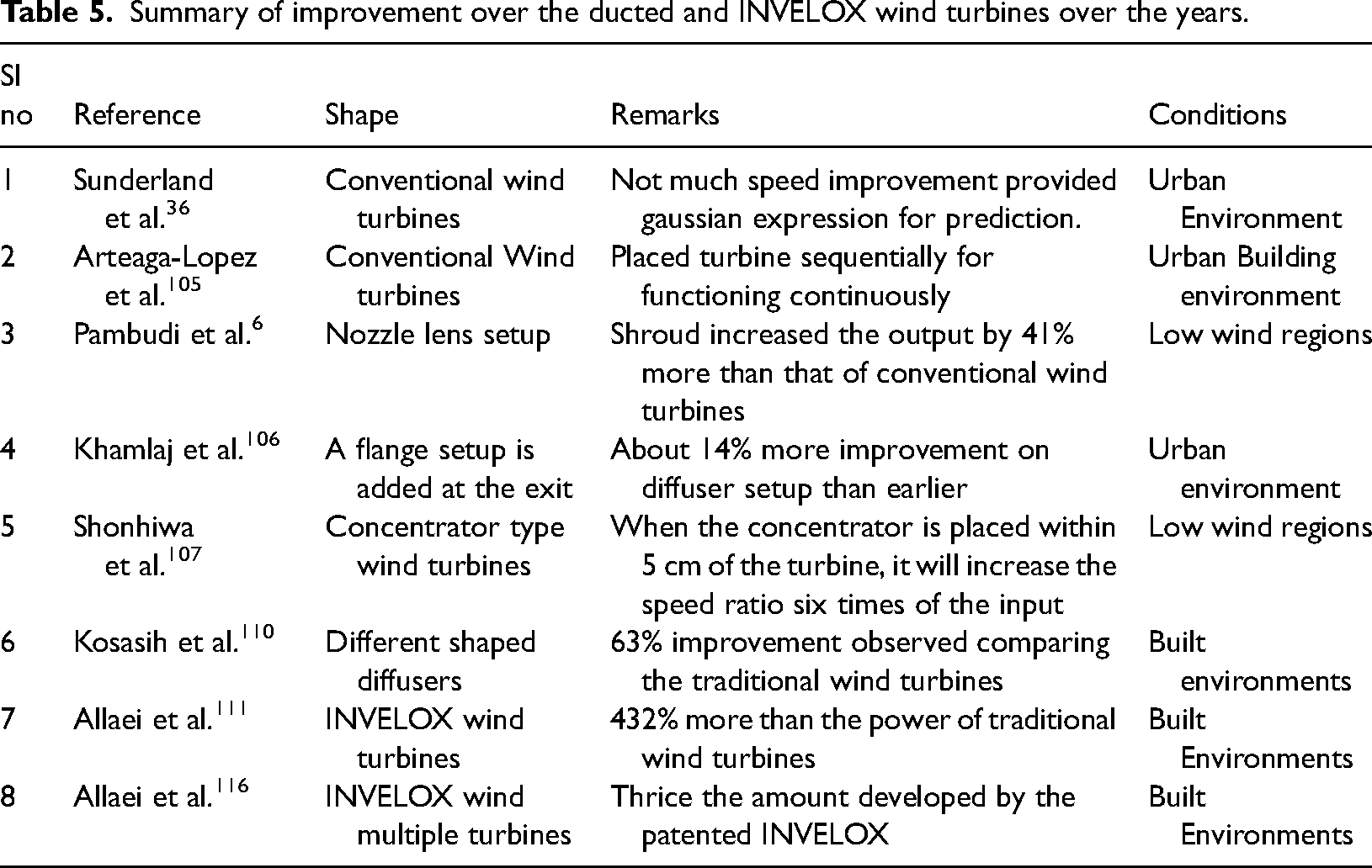
The Summary of ducted methodologies presented in the above sections is listed in Table 5. The development over the years of ducted turbines as the researchers have identified that they are capable of overcoming the BETZ limit
Summary of improvement over the ducted and INVELOX wind turbines over the years.
Abolfazl Pourrajabian et al. 126 presented a new innovative idea of hollow wind turbine blades. They proposed a genetic algorithm for starting the time reduction and improving the power coefficient. A preferred option for the starting time in the objective function and attention on internal and external geometry of the blade resulted in performance enhancement. The results indicated that the hollow blades performed better by reducing inertia than the solid blades at low wind speeds. Similarly, the material reduction due to hollow blades kept the stress under control within the permissible limits. Mostafaeipour et al. 127 developed a novel design of a tree-shaped wind turbine that functioned pleasing, noiseless, and harmless. A floating wind blade frame for dynamic reference was designed by Ayman A. Nada et al. 128 They proposed that the inverse taper blades were more suitable for low tip speed ratio than straight blades. An offshore wind turbine blade moving surface mechanism was proposed by Salimipour et al.. 129 Both torque and power were greatly boosted by this system. In other cases, an increase of up to nearly 95% led to a drop in the tip speed ratio below 5.
The momentum generated due to the moving surface reduced the flow separation in the boundary layers. Chiu et al. 130 presented a new biplane wind turbine blade that exhibited better structural and aerodynamical performance when compared to conventional turbines. The optimized biplane model was nearly 0.45 times lighter than the monoplane model of the same design. The design of the biplane model enabled material reduction with improved resistance, thereby eliminating the edgewise fatigue damage.
Prototype validation on small scale wind turbines
Bani-Hani et al. 131 harvested wind-generated energy due to the vehicular movement on highways and utilized it for minor applications such as lights on highways, signals, and pathway guides. Real-time deployment was a priority when developing a prototype. For an average wind speed of 4.4 m/s, the prototype generated up to 48 watts of power. It raised the efficiency to a maximum of 34.6%. Al-Bahadly 132 built a small prototype turbine capable of producing 0.65 Kilowatts per day. An S-type Savonius type rotor which was 1.5 meters tall and 0.65 m wide, was designed. The rotor enabled a pay-back period of 9.6 years. P.A.B. James et al. 65 built micro wind turbines with photovoltaics to provide carbon-free turbines at the building level. The outcomes revealed that the performance of the micro wind turbines in rural areas was much enhanced than the urban and suburban areas.
A small-scale portable wind turbine was designed by Kishore et al.. 9 The turbine was designed to operate under wind speeds of 5 m/s and yielded a maximum output of 0.83 watts. The turbine's cut-in speed was 2.7 m / s. Evans et al. 133 created a 5-kilowatt aeroelastic turbine model. The experiment utilized a point tracking variable speed control to provide maximal control over rotor aerodynamics and yaw fin dynamics. Freere et al. 14 developed a tiny, low-cost turbine with a 2.1-meter-diameter rotor capable of commencing operation at a speed of 3 m/s and producing 200 watts. While the efficiency was lower, the cost of generating electricity per watt was less expensive than it was previously. The analysis concludes that improving performance can be accomplished by blade optimization and averting wind turbine stalls.
Discussion of summary
This research examines the possible productivity of wind turbine installations in urban environments while taking turbulence into account. In comparison to flat terrains, the particular ambient circumstances present in urban areas make wind energy capturing extremely challenging. Researchers are still on the lookout for a methodology that is suited for these confined situations. The viability and success of small and medium turbines in urban residential areas were investigated. This paper discusses the beginnings of the highly unclear nature of atmospheric boundary layer restrictions and subsequent successful developments by many scholars. Researchers have proposed installing rooftop wind turbines on the area's highest structures. More intensive research is required for turbines to be installed on low-rise buildings. To counteract the urban boundary layer generated, applications such as INVELOX, ducting, and shrouding facilities could provide a stable foundation for low elevated buildings. Despite the adaption of the CFD modelling accuracy in innovative ideas as indicated in the literature, the on-field experimental data with the theoretical formulation of the setup will improve the accuracy even more. A lot of explanation is given for the quick rotation of the small-scale blades compared to their large-scale counterparts. Experimental validation of the large-scale blades with scaled-down models of the same profile and testing at the same conditions can provide insight into their rotational characteristics. More experimental works will enable the derivation of new standards. Buildings of various heights and roughness that create significant turbulence in an urban area should also be considered for numerical validation and wind tunnel testing. Because the turbines will be mounted on the rooftops of dense urban areas, the noise level should be kept to a minimum by using various designs and methods. Simultaneously, the safety of birds flying over the turbines must be assured. The methods proposed for augmenting the wind speed in the urban environment despite their success in the early stages can be developed further for realizing 80% of the power-producing capability of the individual houses.
Conclusion
The performance of small-scale wind turbines was extensively monitored because of the lack of adequate large-scale wind turbines in urban areas. Based on thorough research, the following findings have been obtained. At least 1.3 times the height of the building, the turbines should be placed on the roof. When the wind flow is perpendicular to the turbine, the casing, shroud, or diffuser generates significant amplification. A cycloidal cross-section of shroud increased the wind speed even more. Due to the adverse atmospheric boundary layer, urban wind conditions are highly uncertain. Furthermore, due to the demand for extensive land areas, wind turbines cannot be installed in all places. Wind speed is further restricted in urban residential areas due to obstructions. The turbulence created by these impediments has substantially impacted the performance and potential of small-scale turbines. Placing turbines on the rooftop to eliminate the hurdles, as mentioned above, was the subject of extensive research. The study revealed that the turbine mountings required to be well-designed and positioned. Compared with two-dimensional validation, 2.5-dimensional and 3-dimensional models gave detailed and accurate findings by reducing the disorderliness in the flow towards the turbine. The current IEC 614200 standard proved insufficient for small-scale wind turbines in urban and high-turbulence conditions. The high turbulence increased power developed on a few occasions. But, it affected the turbine blades due to the impact of fatigue load on specific locations resulting in damage. High turbulence on wind turbines negatively influences power generation on most occasions. In small-scale wind turbines, high noise generation was a significant issue. By thickening the trailing edge and tail forms, noise levels during turbine operation were lowered. The flatback trailing edge also provided excellent structural stability. Associated to their large-scale counterparts, the small-scale turbine blades start rotating at low wind speeds. However, they needed a long time to generate electricity because of their high inertia. The methodologies proposed for augmenting the velocity were casing, shroud or diffuser, nozzle lens, diffuser type, and the INVELOX, which could generate a wind speed two times more than the actual wind speed.
Footnotes
Declaration of conflicting interests
The author(s) declared no potential conflicts of interest with respect to the research, authorship, and/or publication of this article.
Funding
The author(s) received no financial support for the research, authorship, and/or publication of this article.
