



Abstract
Inexhaustible energy sources are the focus of the energy industry for meeting the increased need for energy and reducing carbon emissions. Among various alternatives, harnessing solar energy has become a promising choice around the world. Parabolic trough collectors (PTCs) are an effective way to transform radiant energy into thermal energy, as well as electricity. However, these collectors can be improved by refining their design and tweaking the parameters related to thermal behavior. This may be done either by enhancing the surface area or improving the heat transfer coefficient of the heat carrying medium. These kinds of improvements could be achieved by making the use of nanofluids and by using inserts or fins within the collector tube. The current study provides an extensive review of PTCs from the points of view of their design, along with their thermal characteristics. Different types of nanofluids as the working liquid are investigated and discussed to achieve better PTC performance. Inserts within the collector tube and various design approaches, including fins, twisted tubes, U-shaped tubes, coiled wire inserts, and porous twisted tape inserts, are reviewed and discussed in detail. Finally, based on this review, challenges of PTC applications are described and future research recommendations are proposed.
Keywords
Introduction
The expanded global energy need, owing to the fast-growing economies like China and India, has led to an upsurge in the use of fossil fuels in the past decade.1–3 The top 10 countries’ per capita energy consumption and total energy utilization are listed in Table 1. Presently, developing countries are mainly running on fossil fuels to fulfill their energy demand. This is leading the entire civilization toward global warming. The main component of environmental pollution is carbon. Figure 1 shows the cumulative emission of carbon particles to the surrounding over the last century. Now, global concerns about environmental change and limited fossil fuel reserves have pushed the industrial sector to utilize the sustainable source of energy as an alternative to fossil fuels.4,5 Therefore, many countries are developing sustainable practice for energy generation, to reduce the release of greenhouse gases by approximately 40% by 2030 and 80–95% by 2050.6,7 Many countries like the United States, China, India, Japan, the Netherlands, Germany, etc. are interested in the deployment of sustainable energy like geothermal, wave, wind, biomass, solar, tidal, and hydropower. 8 The trend of investment in sustainable energy in several countries is illustrated in Figure 2. 9 The recent changes and future goals on carbon emission and sustainable sources of energy in Asia and Europe are:
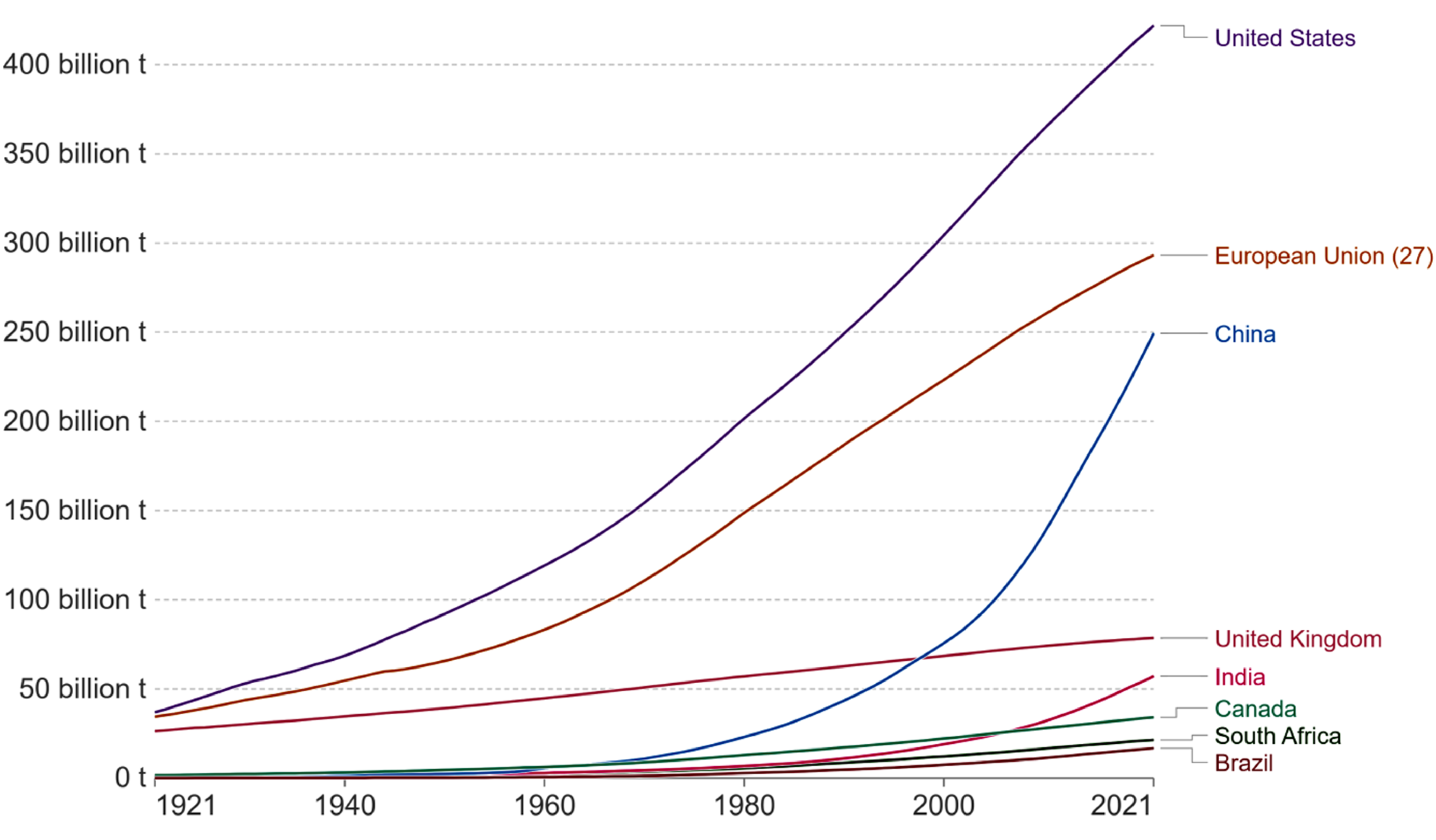
Cumulative emission of CO2 for past 100 years [https://ourworldindata.org/contributed-most-global-CO2].

Sustainable energy capacity investment by several countries with in 2010 and first half of 2019, in US dollar ($) billions. 9 .
Top 10 countries in terms of energy-consuming [World Bank dataset] (https://worldpopulationreview.com/country-rankings/energy-consumption-by-country).

*The values are presented in the form of kilogram of oil equivalent.
In Europe:
Within 2030, the European Union supposes to produce a minimum of 32% of required energy from sustainable sources.
10
In 2020, sustainable sources of energy accounted for 17.5% of the gross consumption of final energy for the European Union, according to the report provided by Eurostat.
11
Near about two-thirds of the total emissions decreased from 1990 to 2020 in the power generation sector, pointing it as the most critical situation to the decarbonization of the economy of the European Union.
12
Within 2030, planning of the European Union is to reduce its ejection of toxic gases by around 55% in comparison to 1990 levels.
13
Within 2030, China is supposed to produce 20% of its total energy from sustainable energy, leading it as a worldwide leader in the generation of sustainable energy.
14
China is planning to decrease its footprint of carbon to zero within 2060 and CO2 release within 2030.
15
Within 2030, India is supposed to have installed power capacity based on sustainable sources of energy at a 40% share.
16
India is the third largest contributor to global warming after the United States and China.
17
In Asia:
Now, by focusing on India, which is a country with huge sources for the production of power from sustainable energy. India produces 58% of its required power from coal burning 85 million tons annually, whereas, only 20% of power generates from renewable energy sources.
18
India has committed to an Intended Nationally Determined Contributions target to achieve 40% of its total electrical power from nonfossil fuel sources by 2030.
19
At present, a total of 74.79 GW of inexhaustible energy capacity was installed in India on 31 December 2018, including 25.21 GW from solar, 9.92 GW from biopower, 4.52 GW from small hydropower, and 35.14 GW from wind.
20
Figure 3 shows the percentage-wise representation of different power sources from renewable energy in India. A quantitative comparison of various environmental and techno-economic factors of renewable energy sources is summarized in Table 2. A major portion of power from renewable sources is based on wind sources though large numbers of sources in terms of solar energy are accessible in several parts of the country. So, various investigations are nowadays going on to achieve more efficient devices for utilization energy from the Sun. The advantages of using this energy include pollution-free, abundant energy resources, easy availability, and noise-free operation compared to other energy alternatives.23–25 The radiant energy received from the Sun can be accumulated by the collectors, known as “solar energy collectors (SECs).” They are broadly applied to convert radiant energy into heat, transferring it into a working fluid such as oil or an organic solvent, air, and water. This collected thermal energy further can be utilized to store energy,26,27 heat space,
28
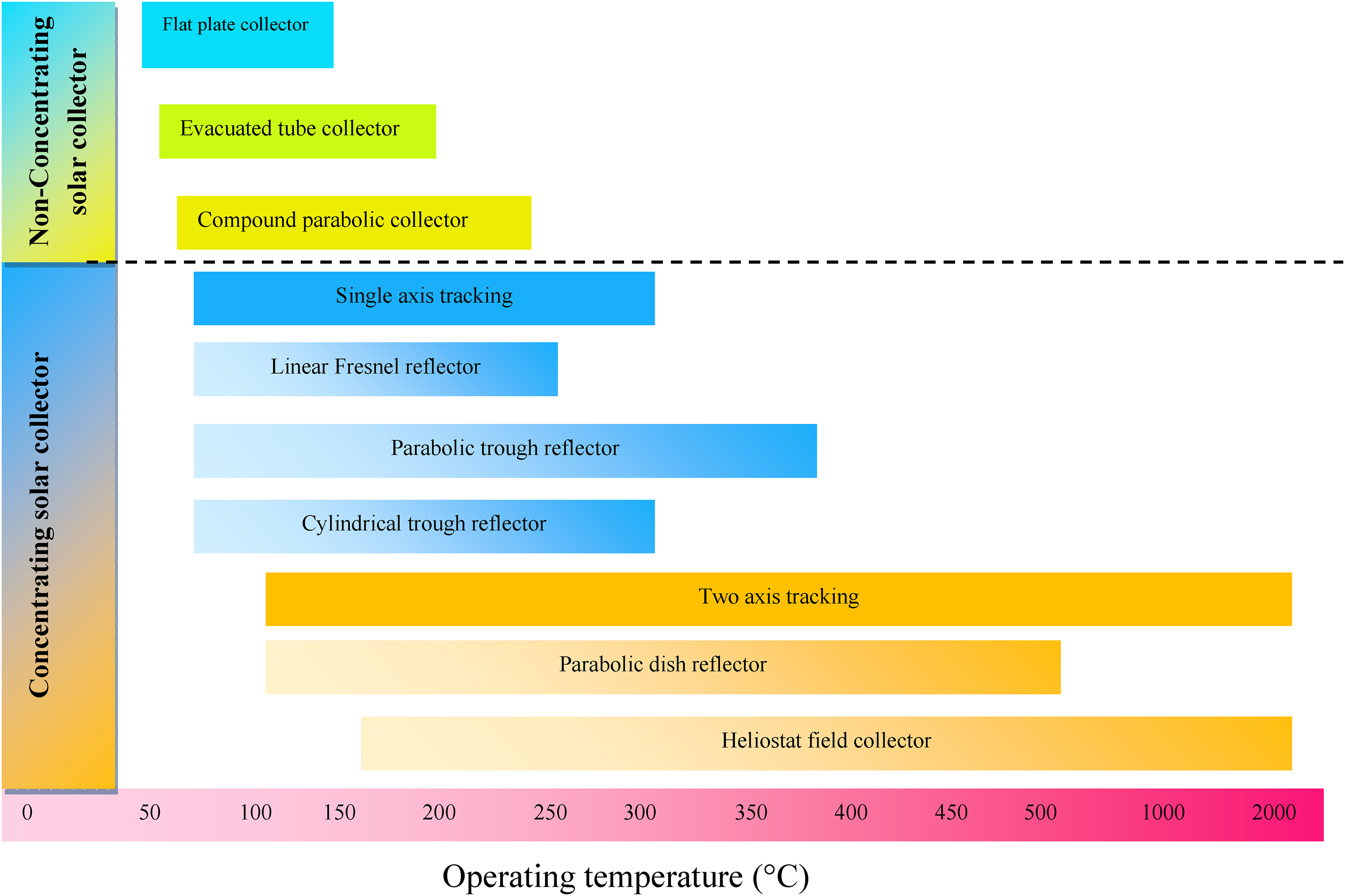
and drying of agroproducts.29,30 Based on the requirement of working temperature, various types of SECs are commercially available for such applications. Generally, these SECs can be categorized into nonconcentrating and concentrating ones.
31
Figure 4 presents the classifications of mostly used SECs with their operating temperature ranges. Among different types of SECs, the flat plate collector is the easiest and cheapest method of transforming solar radiation in the form of thermal energy, which provides a temperature range of 120°C to 140°C.32,34,35 However, these nonconcentrating types of collectors are not appropriate for those solar thermal applications where the requirement of temperature is very high, such as steam generation and desalination process. But concentrating solar energy collectors provide an efficient solution to fulfill thermal and electrical energy demands. Among SECs, the parabolic trough collector (PTC) is a promising technology to supply low-temperature and high-temperature heat.32,35 PTC utilizes energy directly from the Sun and converts it into some other type of energy. So, throughout the entire method of energy generation, no harmful toxic damaging gases are emitted to the surrounding and it is having the capability to meet the growing demand for energy associated with evolving civilization. PTCs play a crucial role in reducing carbon footprint by restricting greenhouse gas emissions involved in power generation. PTC also provides flexibility to use this on small or large-scale and a small-scale PTC system can easily transform into a large-scale PTC system, simply adding a number of collectors. Although PTC has a high initial investment in the long-term, it was observed to be economically viable because of its low operating cost. PTCs have a broad range of applications. It can be applied in absorption refrigeration systems, domestic hot water for public places, space heating, and concentrated solar power (CSP) plants. In PTCs, as displayed in Figure 5, the incoming radiant energy is concentrated on the focal axis, where a tube collector containing a working medium, namely, molten salt, water, gases, or synthetic thermal oil, absorbs the solar energy from the collector's surface.
35
A spectrum selective coating (i.e. nickel-cadmium coatings) on tube collectors is commonly used to gain least infrared radiation and highest solar energy absorption (short wave) emittance.
37
Several research efforts on coatings have been made, and more than 95% thermal radiation properties of the collector have been achieved.

Installed grid-interactive renewable power capacity in India. 21
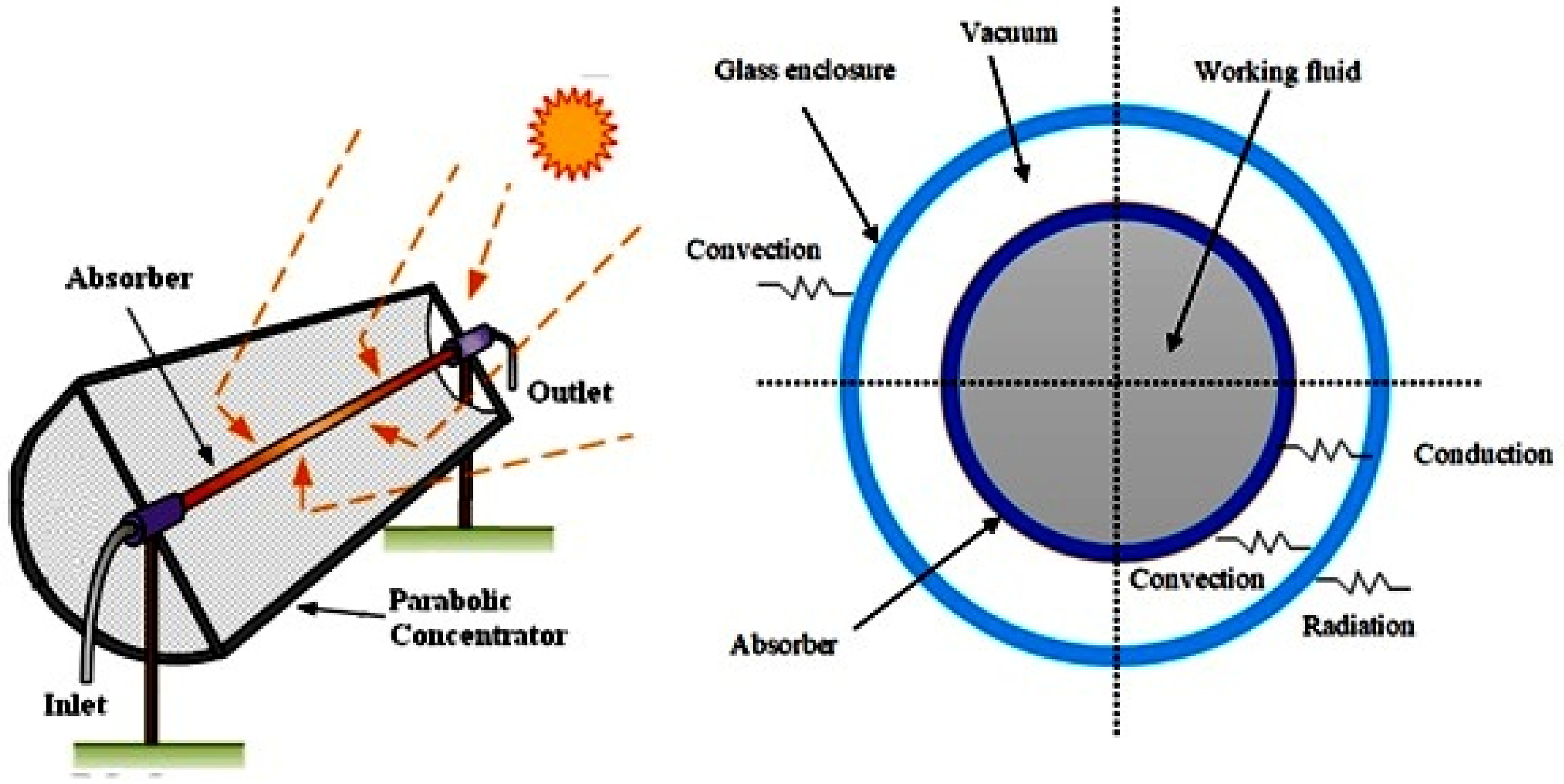
Schematic structure of (a) PTC system; (b) absorber tube. 35
Environmental and techno-economic factors of renewable energy sources. 22

* Negligible; + contributes; − does not effect.
The highest temperature in PTCs can reache up to 400°C.33,38 Thus, it becomes important to supply maximum heat to the working medium in the collector. Otherwise, an increase in emissivity of the selective collector coating will cause radiation heat loss, resulting in poor thermal performance of the PTC. Moreover, at high temperatures, tube failure or damage to the external glass cover due to excessive thermal stresses may lead to vacuum loss. 33 Hence, improving the design and thermal performance of PTC are of major concern. The effectiveness of a PTC can be enhanced either by increasing the convective heat transfer surface area or raising the heat convection coefficient inside the receiver and tube. 39 In a same direction, moderate research efforts on the investigation of PTCs have contributed to the substantial progress of this technology, making it competitive with counterpart technology.
The PTC-based solar power plants, working at present, are displayed in Table 3. At present, worldwide, there are a total of 116 PTC plants are operational, with a total capacity of 6415.9 MW. Spain has the largest running capacity of 2304.9 MW, followed by the United States with 1726 MW. The oldest commercial PTC plant still operational is Solar Electric Generating Station III (the United States), which has a rating of 30 MW. However, the CSP plant with the largest capacity operational is Ivanpah Solar Electric Generating System (the United States). It started working in 2014 with a capacity of 377 MW.
Operational PTC-based CSP plants around the world. 40

CSP: concentrated solar power; PTC: parabolic trough collector.
This article provides current knowledge on improving the thermal characteristics of PTCs, which deals with altering the design of conventional PTC, such as providing turbulators to augment heat transfer or using nanofluids. The current status of the PTC-based commercial concentrating solar plants worldwide is highlighted in detail. Finally, a summary of future research, challenges, and applications is provided.
Thermal performance analysis of PTC
Solar thermal technologies contain various low-temperature, medium-temperature, and high-temperature collectors. These PTCs are again classified as nonconcentrators and concentrators. The nonconcentrators generally use various heat-absorbing materials to capture solar energy. In contrast, the concentrating collectors focus sunlight using mirrors and lenses. The solar concentrators are categorized as tracking and nontracking types. Tracking concentrators are continuous or intermittent and have one or two axis types. Solar collectors are categorized based on optical constituents: (a) refracting or reflecting type, (b) imaging or nonimaging type, and (c) point focusing or line focusing type. There are various methods by which the flux of radiation on the collector can be increased. A brief classification of solar concentrators is elaborated in Figure 6.

Working principle
PTC is also known as a linear parabolic collector or cylinder parabolic collector, having the following primary components: (i) the receiver tube (also called a collector tube) fitted at the focal axis, through which a flow of liquid is heated, (ii) the transparent concentric glass cover, and (iii) the reflector of parabolic shape. Stainless steel or copper is commonly used to fabricate absorber tubes and needed to be painted with a special black color of high absorptivity. PTCs are line-focus-type concentric collectors. They condense direct solar irradiation on their axis. The working medium absorbs the energy of sunlight from the tube walls. The selection of the heat conveying medium is done on the basis of the outlet temperature needed for the specific use. Generally, the organic heat transfer fluid, commonly called thermic fluid, is considered for this purpose due to its lower thermal conductivity as well as lower heat transfer coefficient. The parabolic-shaped reflector is usually made of curved back silvered glass. However, it may be made by steel plate or even a wooden frame with a reflecting sheet attached at the top to reduce the cost and eliminate the chance of breaking during long transport. A PTC may be fitted in an east–west (E-W) or north–south (N-S) direction with its focal axis. Orienting it toward E-W results in a horizontally aligned focal axis, whereas the N-S direction of the focal axis may be inclined or straight. The aperture area of the collectors may vary between 1 and 60 m2. The concentration ratio is one of the prime parameter as far as the parabolic trough design is concerned.
44
It is defined as:
Mathematical formulation
Under steady-state operation of PTC, thermal efficiency for the collector's can be obtained as follows
45
:







Energy performance
A PTC is mostly utilized to transform radiant energy into thermal as well as electrical energy by concentrating the incoming radiation falling on it. In a PTC, the collector tube is covered by one glass tube that is perfectly evacuated with antireflective coatings, and Therminol VP-1 is mostly considered as the working medium. According to Sandia National Laboratories, tests performed for a conventional PTC provided superior collector efficiency with lower thermal loss for the LS-2 model. 50 Cermets and chrome black selective coatings were utilized and investigated along with configurations for three collectors. Glass tube was considered evacuated or filled with air, sandwiched between the collector annulus and the receiver. Development of correlations for the performance of a collector in terms of thermal loss and efficiency of heat carrying liquid was conducted by taking simple polynomial correlation from test data. A modifier with the incidence angle of the LS-2 model of PTC was also evaluated by taking the efficiency of the same for varying angles of incident radiation. 50 One optical model for PTC was generated and investigated by Heinzel et al. 51
Direct generation of the steam from the collector was investigated to reduce the cost related to the synthetic oil. 52 The formation of electricity from solar Rankine cycle-based thermal power plants by the direct generation of steam along with PTCs was conducted by Yazdi et al.53,54 The investigation indicated that analysis of exergy and the total monthly average exergy efficiency of the power plant varied between 70% and 85% for a year. Dagan et al. 55 and Lippke 56 proposed three innovations for a Direct Steam Generation (DSG) collector system. The first innovation was the generation of steam for a single pass. The second idea to re-circulate the fluid was to produce wet steam and control the steam quality by the injected water and flow stability in the collector tube.57,58 Investigation of low-pressure-based steam generation system produced heated water in the receiver and then flashed the steam in a different container. The flow in the receiver was utilized in the steam flash method to maintain the flow in the collector.55,59 However, very few works were reported to measure the performance of energy transport of big PTCs considering a straight boiling process for the production of power. Odeh et al. 60 investigated a thermal model to obtain heat loss because of a temperature drop between the collector wall and heat transfer fluid (HTF) temperature. They claimed that the model could be used for any HTF. A schematic diagram for the LS-2 model of PTC is shown in Figure 7.

LS-2 model of PTC. 76 PTC: parabolic trough collector.
Exergy performance
The Sun is the origin of radiative energy and not a usual source of thermal energy. The rate of exergy supplied by energy from the Sun is a much-discussed topic. For this fact, larger numbers of parameters must be taken into inspection to obtain its rate of exergy flow. The most appreciable model is based on Petela theory
61
and can be written as


Munoz and Abanades 65 noted temperature gradients and thermal losses to reduce the collector's exergy and thermal efficiency increment. Bellos and Tzivanidis 66 indicated that flow inserts caused performance increment in overall thermal and exergy efficiency criteria. Mwesigye et al. 67 obtained the changes of energy and exergy in the case of trough collector by using single-walled carbon nanotubes. The generation rate of entropy was obtained directly from the temperature and local fields of velocity for the computed regions and later considered in the examination of exergy. Joseph et al. 68 pointed out that the rate of flow is a prime factor in order to improve collector's efficiency. However, exergy efficiency was reduced for both nanofluid and water. The peak value of thermal efficiency has reached 64.05% at 90 l/h. This corresponded to a 48.19% improvement to that of water. The utilization of nanofluid is found to improve the exergy efficiency by 9.4% at 60 l/h as compared to water. The performance of the Kalina cycle in combination with PTC was investigated by Zare and Moalemian. 69 The utility of the Kalina cycle with PTC provides an exergy efficiency of about 64% and the exergy efficiency of the overall power plant of 14%. From the commercial viewpoint, the higher number of collectors per row was further influential to that of the larger number of collector rows.
Advances in thermal enhancement methods in PTC
Many researchers have attempted to explore PTC by modifying its different components to track the improvements in performances, which are summarized in Table 4.
Varioustypes of modifications done to PTCs and their effects.

PEC: performance evaluation criterion; PTC: parabolic trough collector.
PTC with twisted tape inserts
Over the years, several improvizations have been demonstrated to improve the characteristics of energy transport of the trough collector. Insertion of twisted-shaped tape is considered one of the passive methods of enhancing the thermal changes of solar trough collector. The two vital parameters of the investigation are the twist ratio (ratio of one twist length and twist diameter) and clearances between the tube the tape and wall. The higher the twist ratio the lower is the swirl in the flow. This is accountable for the reduction in case of the heat transfer rate. 122 In fact, a low twist ratio of just over one delivered better mixing, and an extended helical path improved the thermal enhancement factor and efficiency. 111 Besides, heat transfer may also have a detrimental effect if the tape and tube wall clearance increases the resulting by passflow. 123 However, in the high turbulence regime of 5000 to 25,000 Reynolds number (Re), the Nusselt number was around 2.9 times larger than that of the plain tube for a twist ratio of 2. 102 Further, the highest value of the collector wall temperature was reduced at lower clearance ratios. The performance of PTC using a twin-twist insert in a receiver was inspected by Eiamsa-ard et al. 85 The highest discrepancies between experimental and correlative findings of friction factor and Nusselt number were observed as ±6% and ±10%, respectively. The use of wavy tape inside the collector was numerically explored by Zhu et al., 86 taking uneven heat flux of solar energy. Syltherm 800 was considered the HTF. In this analytical work, the average global Nusselt number was augmented by 261–310%. This is responsible for a reduction of total heat loss and structure temperature. The heat loss was noted to decrease by 17.5% to 33.1%, based on the flow rate. The consideration of a wavy-tape insert is an effective manner to improve localized heat transfer that affects the vicinity of its two flanks. Bhuiya et al. 82 found the influence of porous twisted-shaped tape (Figure 8) on the thermal changes of parabolic solar trough collector. Thermal performance factor, friction factor, and Nusselt number for the tube were observed to be 28–59%, 110–360%, and 110–340% more than that of typical tube collectors, respectively. The performance of PTC by fixing twisted tape (TT) inside the receiver (Figure 9) through which thermal oil flowed was inspected by Jaramillo et al. 88 It is noteworthy that the friction factor, Nusselt number, and efficiency of PTC augmented than empty collector tubes for both ratios of twist (y/w). Borunda et al. 124 applied multi-objective genetic algorithms to investigate the influance of twisted-shape tape in a collector tube. According to them, the increase in the efficiency of a PTC does not always reflect the betterment of the thermal enhancement factor. The comparative analysis of Nu and f with respect to Re are shown in Figure 10.
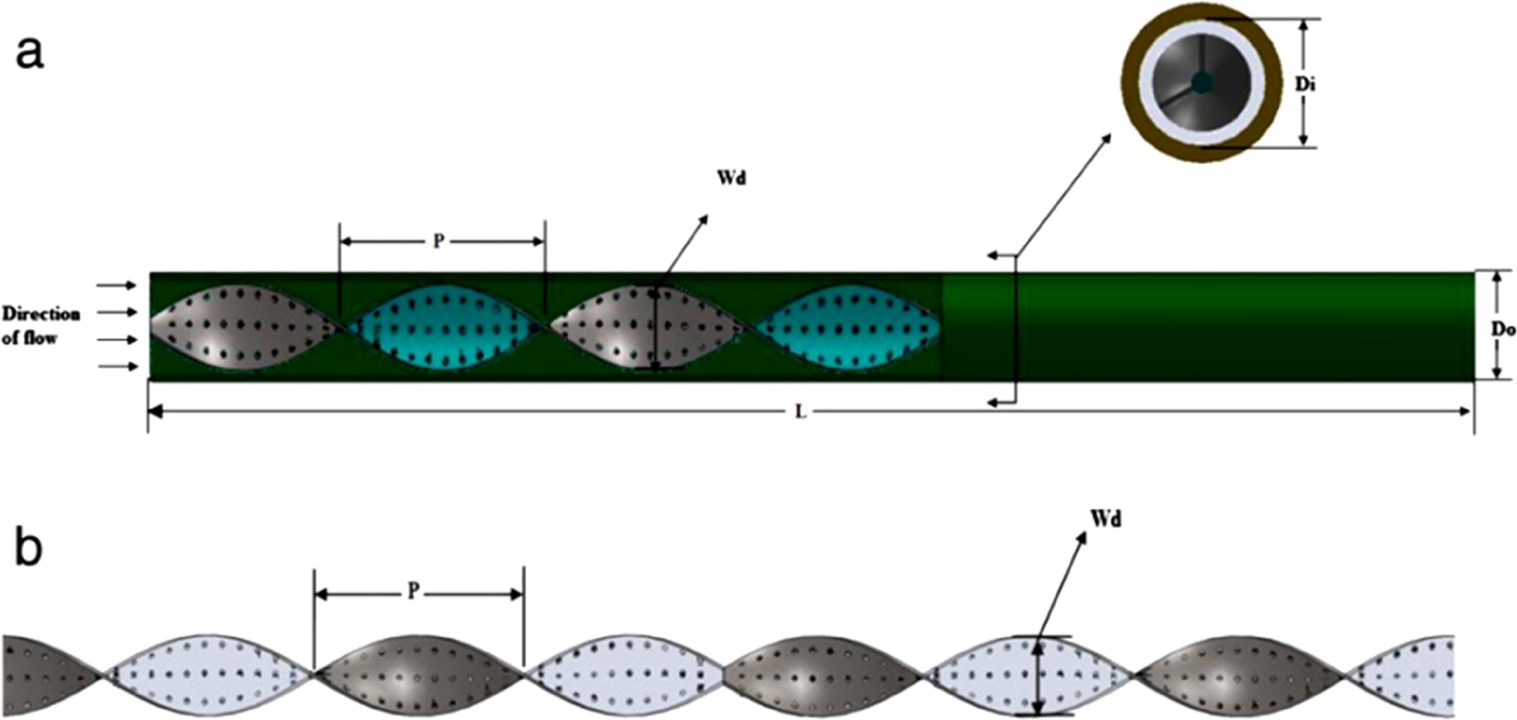
Porous twisted tape insert. 82
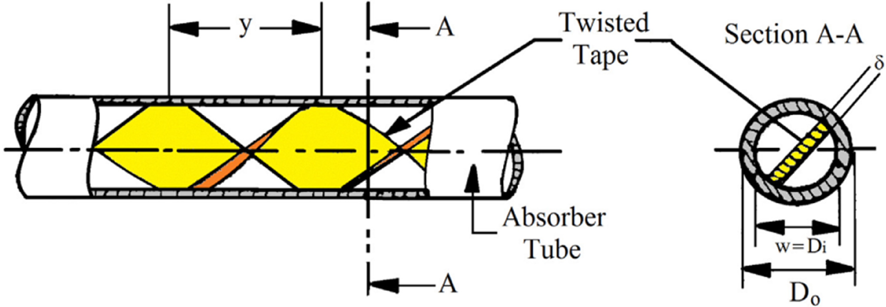
Twisted tape inserts in collector tube. 88
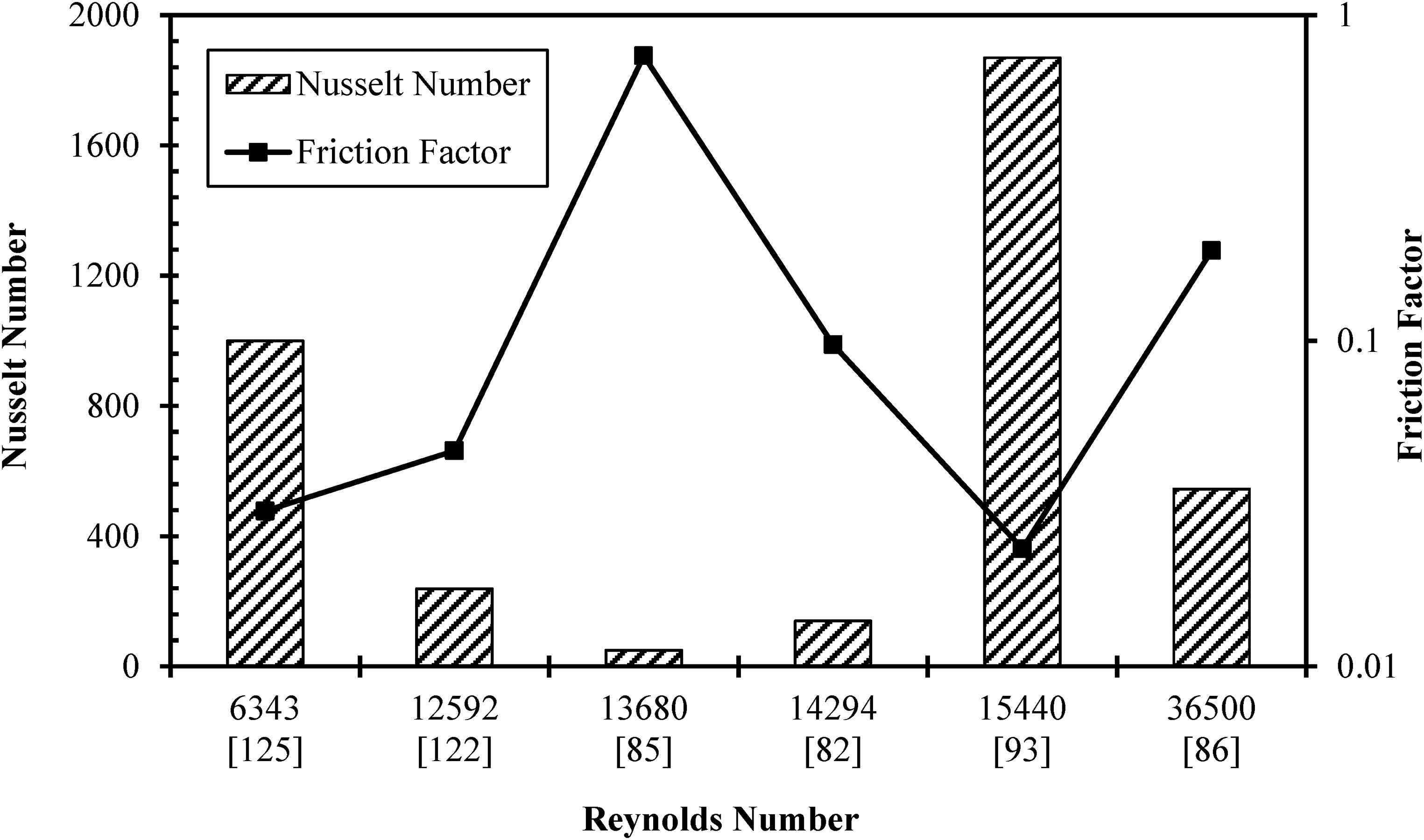
Comparative analysis of changes of Nu and f with respect to Re.
PTC with coil inserts
Yılmaz and Mwesigye 70 fitted one wire coil in the receiver of the PTC. The analysis showed that consideration of wire coil inserts improved the performance of energy transport inside the receiver by around 183% than the typical collector tube. It is found that the use of inserts significantly decreased the amount of entropy generation rates. The heat transfer enhancements of 2.28 times were reported by Şahin et al. 80 using wire coil inserts within the Re range of 3000 to 17,000. The wire coil swirl flow enhances and interrupts the generation of a boundary layer near to the tube wall. 125 Thermal behavioral changes by taking coiled wire with equilateral triangle structured cross-sectional area in a conventional tube (Figure 11) were investigated by Gunes et al. 87 Re of 3500 to 27,000, three-pitch ratios (P/D) of 1, 2, and 3, and two equilateral triangle length to side ratios (a/D) of 0.0714 and 0.0892, were used for experimentation. Coiled wire inserts significantly improved the collector tube's pressure drop and heat transfer. The wire with a/D = 0.0892 and P/D = 1 for Re = 3858 provided maximum efficiency of 36.5%. The rise of P/D, causing the decrease of the friction factor was reported by Munoz- Esparza and Sanmiguel-Rojas. 126 However, according to Diwan and Soni, 110 the pitch values below 8 mm were better for improving thermal enhancement factors at low rates of flow. For high rates of flow, the pitch values above 8 mm provided superior results. Eiamsa-ard et al. 98 reported that their study with a constant and intermittently changing pitch ratio of wire coil (D/DI-coil) and with and without TT. According to them, at the low value of Re, the TT and the DI (decrease-increase) coil is responsible for the best thermal performance than the lone uses of wire coil, TT, TT with D (decrease) coil, and TT having a uniform wire coil. A comparative representation of the thermohydraulic performance factor alobg with the Re is elaborated in Figure 12. The work of Choudhari and Taji 127 showed that friction factor and heat transfer rate improved by applying copper as the material of wire coil to that of aluminum or stainless steel. A 44% mixture of propylene glycol with water (PG 44%) having a higher density as well as dynamic viscosity and lower specific heat also thermal conductivity compared to water was tested. The existence of a wire coil improved the heat transfer by 400% for distilled water and 100% for PG 44% to that of without one. 128
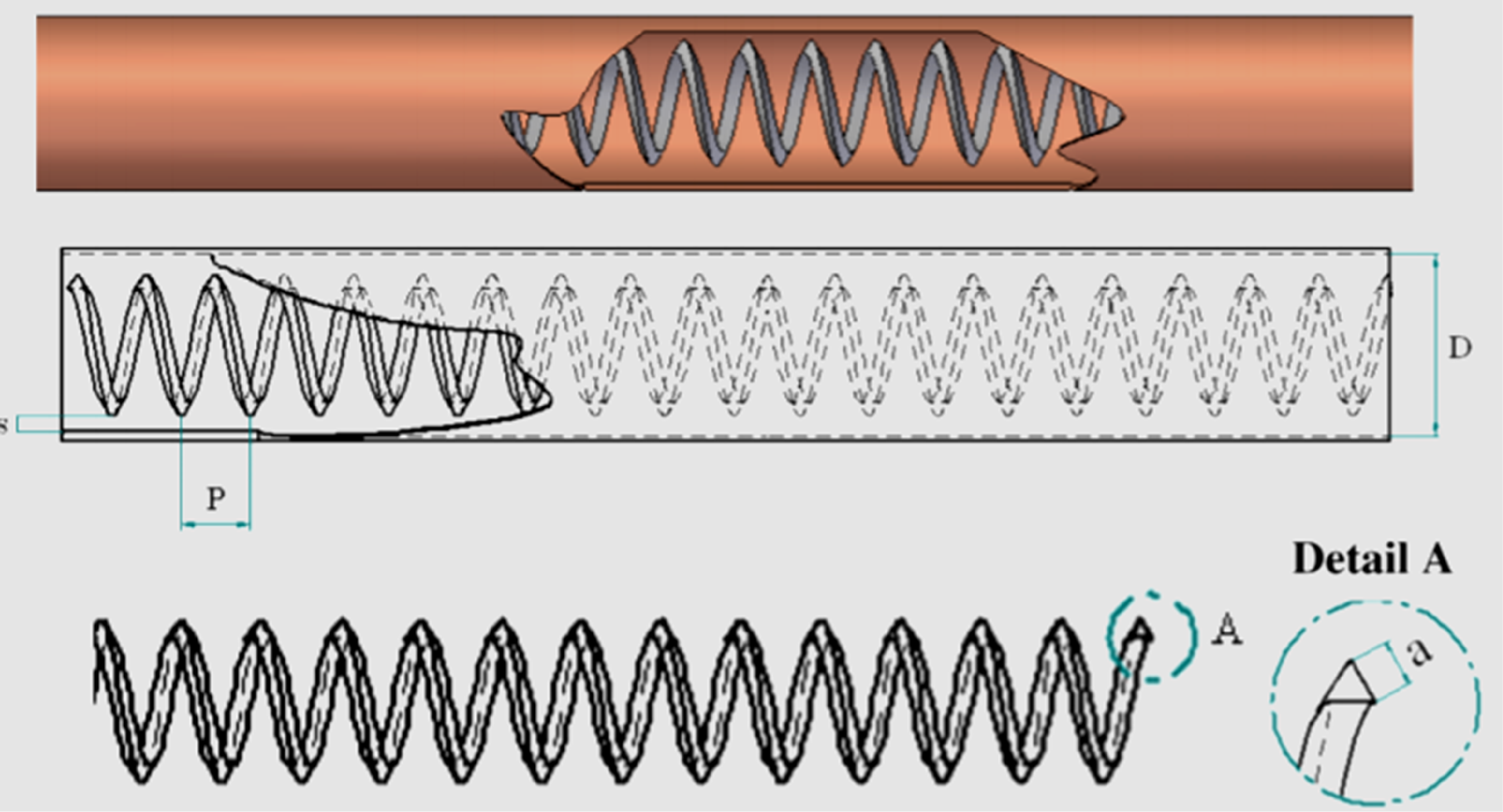
Coiled wire inert in collector tube. 87

Comparative presentation of the thermohydraulic performance factor of PTC.
PTC with porous insert
The heat transfer process can be enhanced with a porous insert in the PTC, caused by the superior mixing ability of fluid and higher conductivity in porous structure. 129 Moreover, a porous insert helps in uniform temperature distribution in the PTC during nonuniform conditions of heat flux, lowering the thermal stress generation. Kumar and Reddy 115 performed a three-dimentional (3D) computational analysis by inserting a porous disc in the collector tube (see Figure 13) and found a 64.2% enhanced Nusselt number with 457 Pa more pressure drop in the case of the optimum modified collector tube. They also studied the inclination angle (30°, 45°, and 60°) of the porous discs and observed that the increasing inclination angle reduced the Nusselt number and higher the pressure drops. Further, they also studied different orientations and positions of the porous discs. They reported that porous disc oriented in alternative top and bottom-half along the length of the receiver tube provided a higher value of Nusselt number than other orientations of the porous disc. Reddy et al. 73 examined the effect of porous disc insert in collector tubes with six varying collector configurations according to ASHRAE 93–1986 test procedure. Depending on the experimental study, the thermal changes of PTC along with alternative porous disc collectors was noted to be better than other collector configurations. Porous inserts in the collector increased the pumping demand by 0.05 W/m for alternative porous disc collectors. Ebrahim and Akbar 84 investigated installing porous rings in the receiver tube. The maximum Nusselt number was observed as 374.63 at an Re of 30,000. Numerical outcomes of the investigation showed that the performance in the form of thermal changes and energy transport in the receiver with the porous ring were appreciably enhanced. Further, the Nusselt number improved with increasing ring size. Jamal-Abad et al. 130 reported the utilization of fixing copper foam in the tube of PTC. The thermal efficiency of the tube was improved with increasing rate of flow. Overall, the loss coefficient was reduced by 45%, and it caused an efficiency increment for less energy loss. In the case of saturated water porous foams, the effect of porosity (95% and 90%), pore diameter (30PPI-10PPI), and type of material (SiC and CuO) were studied by Valizade et al. 131 The extinction coefficient for porous foams was improved by decreasing the pore diameter and porosity. Compared to the outcomes obtained for nanofluid and porous foam for the same material, there was no appreciable change in extinction coefficient in case of CuO nanofluid (0.1% concentration in water) and CuO porous foam (90%, 30PPI). The numerical examination of the effect of an annular porous structure around the collector tube (Figure 14) was performed by Bozorg et al. 132 According to them, the heat transfer coefficient as well as thermal efficiency improved with the Darcy number, whereas the pressure drop in the collector tube showed opposite trend. The porous structure helped increase the thermal efficiency; however, no significant enhancement of thermal efficiency was observed at higher Re and smaller Darcy numbers. Kumar and Reddy 133 inserted porous metal foam at the lower part of the receiver as a potential method of reducing thermal stress generation in the collector tube (Figure 15). They observed that the metal foam helped in reducing the maximum temperature difference by as much as 72%. They also found that the performance evaluation criterion (PEC) and Nusselt number were 5 as well as 10 times higher with the metal foam insert. Metal foam inserts boosted the exergy as well as energy efficiencies by 2.32% and 3.71%, respectively. Gradient metal foam (GMF), as shown in Figure 16, was used by Peng et al. 134 instead of regular uniform metal foam (UMF), and a comparison was made among GMF, UMF, and plain tube PTC. They found that the exergy efficiency and PEC with GMF were improved by 12.8–33.3% and 66.4–227.3%, respectively, compared to UMF. They also found that GMF with lower porosity at the outer layer and higher porosity at the inner layer provided higher thermal enhancement. PTC with GMF resulted in 43.7–812.6% enhancement in Nusselt number and 4.2 to 16.7 times higher friction factor than plain tube PTC. Peng et al. 135 used a hybrid metal foam structure (Figure 17), combining fin and semi-annular metal foam, and found that the hybrid one had a maximum of 234.7% PEC and 11.8% exergy efficiency improvement. They observed that the highest enhancement in the Nusselt number and friction factor was 838.7% and 788.8%, respectively. They also varied different shapes of fins in the hybrid model and found that the triangular fin enhanced the thermohydraulic performance more than the trapezoidal and rectangular fin.

Cross-section view of collector tube with inclined porous disc. 115
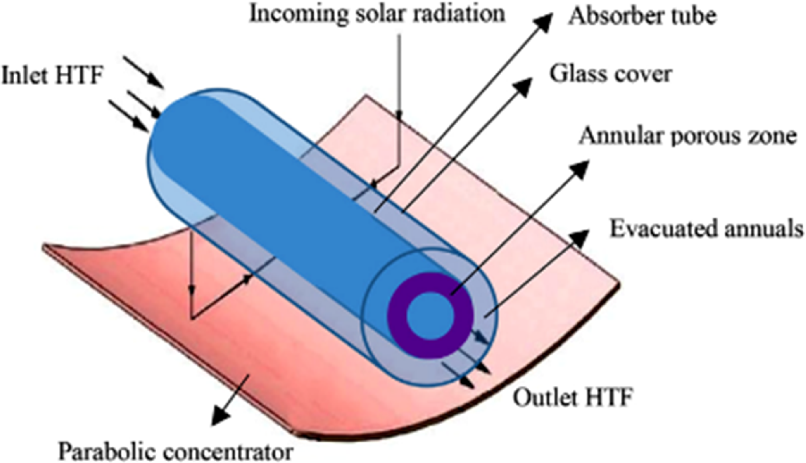
Absorber tube with an annual porous structure. 132
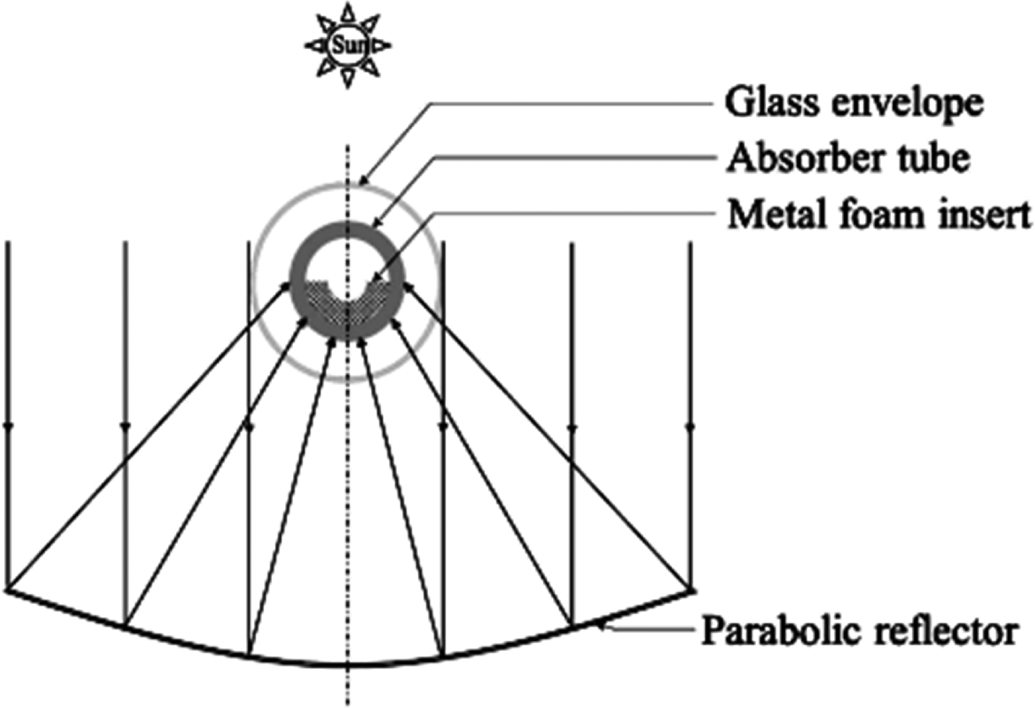
Metal foam inserted in the PTC. 133
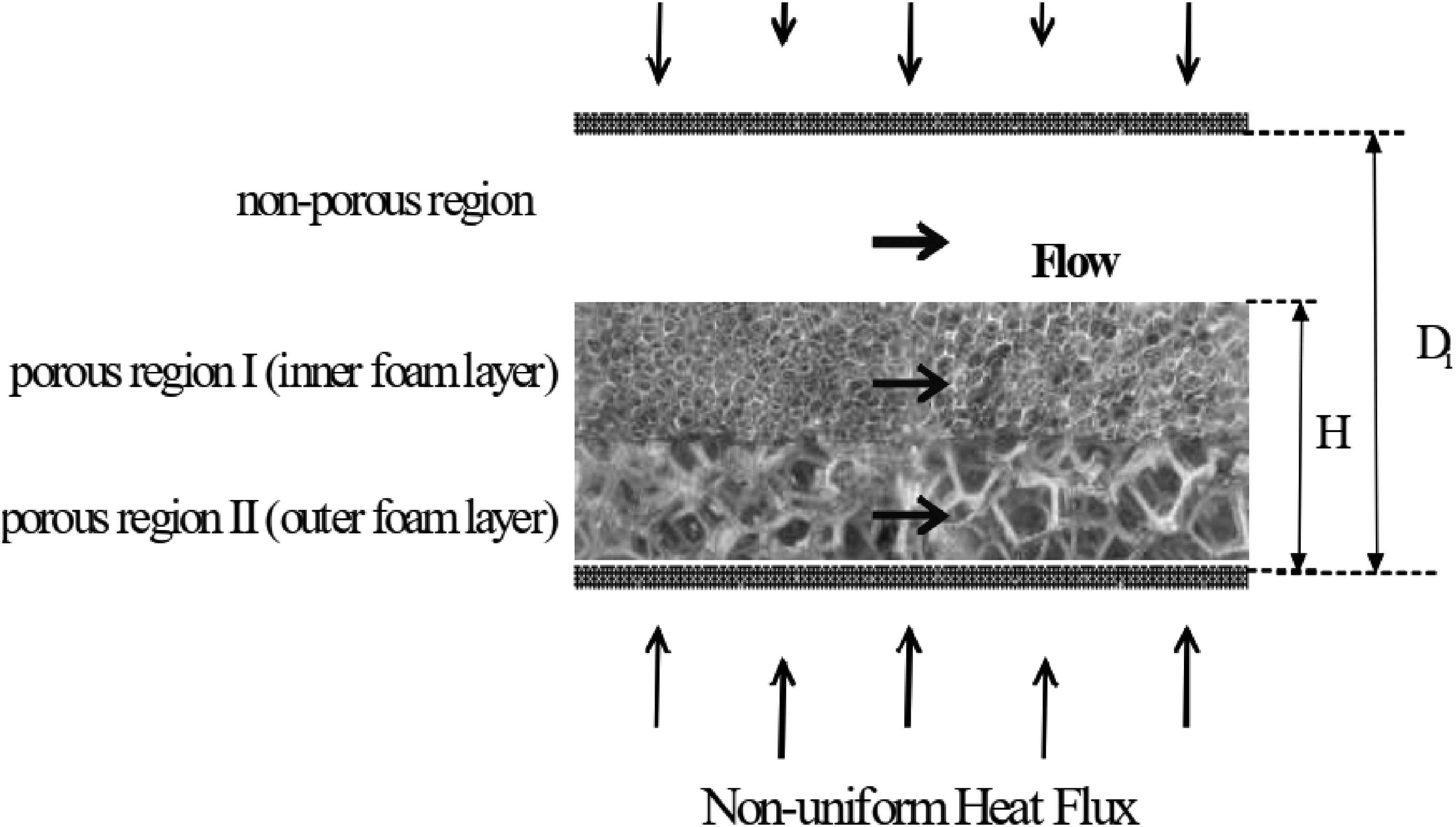
Collector tube with gradient metal foam. 134

Collector tube with hybrid metal foam. 135
PTC with ribs and fins on the inner surface of collector tube
Another approach to improve the process of energy transport in the collector tube is the addition of ribs or fins at the interior of the receiver. The addition of fins increases the available surface area required to transport energy. The obstacles in the flow direction help to break the viscous sublayer to transfer more amount of heat. Munoz and Abanades 65 considered a receiver fitted with a helical fin at the interior. The investigation showed how the parasitic losses due to the tube's pressure losses are affected by a number of fins and helix angles. Again, temperature gradients and thermal losses were noted to reduce the collector's exergy and thermal efficiency increment. The result showed a performance enhancement of 2%, with some amount of depletion in the maintenance and operation cost because of the reduced tube replacement rate. Zheng et al. 79 tested the thermal changes of PTC for double-inclined ribs. It is reported that the increment in the rate of energy transport was 1.8 to 3.6 times. The PEC value was reduced with increasing rib pitch ratio and improved with the rib length ratio. For inclination angle of a rib as 37.5°, maximum values of PEC were obtained. In the place of a smooth collector, the inner surface with dimples were considered and numerically inspected by Huang et al. 91 Re of 2× 10⁴ and numerous values of Grashof numbers from 0 to 3.2 × 10¹⁰ were used for analysis and 1–21% enhancement in Nusselt number was noticed. A study by Xiangtao et al. 89 revealed that a receiver with sets of pin fins was able to get increments in terms of thermal parameters such that the total heat transfer performance factor and average Nusselt number improved up to 12.0% as well as 9.0%, respectively. Bellos et al. 136 analyzed a PTC to obtain the thermal behavioral changes for the internally finned collector. Twelve varieties of fin conformation were investigated and compared with typical collector tubes for varying operating conditions. It is noted that larger fin thickness and fin length take to an improvement in thermal performance with a penalty of pressure drop. However, the influence of fin length was seen to be more effective than the thickness in the results. They recommended the model with 4 mm thickness as well as 20 mm length is the most effective one, which had 2.65 times higher Nusselt number, 1.483% thermal enhancement index, and 1.27% higher thermal efficiency in comparison to the conventional receiver tube, operating at a temperature of 600 K at the entrance. The analysis of Bellos et al. 76 showed optimal location with one fin at the bottom side of the collector (β = 0°), resulting in thermal efficiency of 68.40%, which was 0.16% higher than conventional PTC. Figure 18 shows the optimum position of two fins on the bottom side of the collector (β = 0° and 45°). Using two fins, thermal efficiency improved by 68.50% compared to the tube's efficiency with a single fin. More fins caused a larger value of thermal efficiency and pressure drop. Again, the PEC was observed to increase with an enhanced fin number. It is concluded that the collector with three fins in the lower part provided the best thermal efficiency of 68.59%. Zhao et al. 137 analyzed the receiver tube with pin fin (see Figure 19) to increase the performance of PTC in heating applications. The air temperature rose to 266°C when the flow rate was 93 Nm3/h. The observed exergy and energy efficiency in the case of internally pin-finned absorber tubes were 2.55–4.29% and 10.4–14.5% higher than the conventional absorber tube.
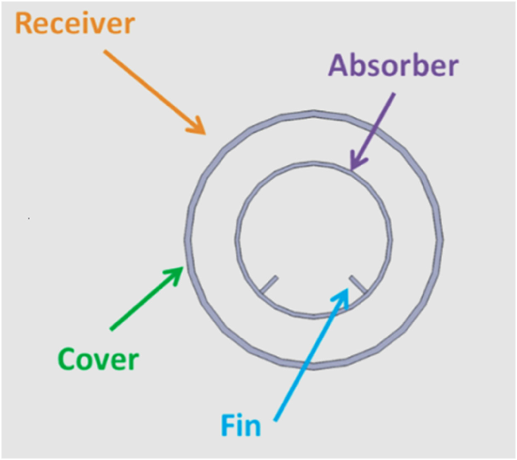
Fin on the inner surface of receiver tube. 76
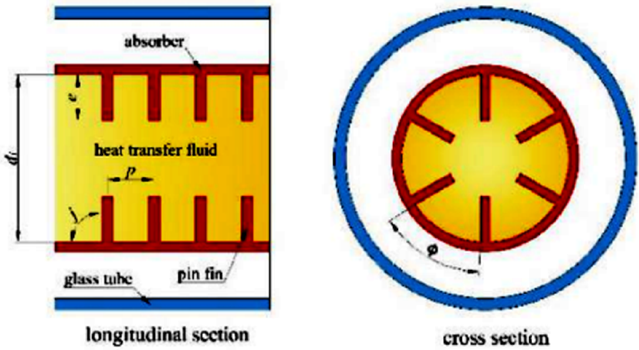
Pin fins on the inner surface of the receiver tube. 137
PTC with different shapes of collector tube
Few researchers modified the regular tubular absorber tube into some shape to increase the heat transfer phenomenon. Bellos et al. 95 numerically evaluated the effectiveness of converging-diverging shape on the thermal changes of PTC. Collector parameters, like efficiency, heat loss coefficient, collector temperature, and pressure losses, were analyzed for all examined cases considering nonuniform flux conditions. They observed that the geometry modification enhanced the efficiency by 4.55%. Fuqiang et al. 97 used a convex corrugated collector tube (see Figure 20) to enhance the performance of PTC. They found that the modification led to a maximum increment of 148% in the thermal performance factor. The modification also helped in uniform heat distribution, resulting in a 26.8% reduction of Von-Mises thermal strain. Bitam et al. 107 studied a novel type of sinusoidal collector tube (see Figure 21) numerically. The maximum temperature difference was reduced to 35 K due to the uniform distribution heat in the modified collector tube. It helped in the reduction of thermal stress. They found that the modified collector tube enhanced the Nusselt number as well as friction factor as much as 63% and 40.8%, respectively. The PEC observed to be 1.35 showed the benefit of using a sinusoidal collector tube instead of a regular plain collector tube. A symmetric wavy collector tube (see Figure 22) with varying amplitude and wave numbers was numerically evaluated by Yang and Ordonez. 138 They observed that the first law efficiency was significantly improved at a larger mass flow rate due to better energy transport inside the collector tube. The maximum PEC was observed as 1.25. It is also observed that beyond the amplitude of 0.006 m, the PEC is lower than unity because of a higher pressure drop incurred in the collector tube. They suggested using a symmetric wavy collector tube with a smaller amplitude and wave number for higher heat transfer enhancement. Khelkar et al. 139 computationally investigated a collector tube with a sinusoidal inner surface considering Therminol VP-1 and water as heat carrying mediums. They noted that the modified collector tube provided 8.09 and 1.03 PEC with Therminol VP-1 and water, respectively. A copper receiver tube with dimpled for water heating was tested experimentally by Munusamy et al. 140 The outcomes revealed that the best results were found with 2.5 kg/min flow rate and maximum raise for the overall thermal efficiency was up to 31.85%.
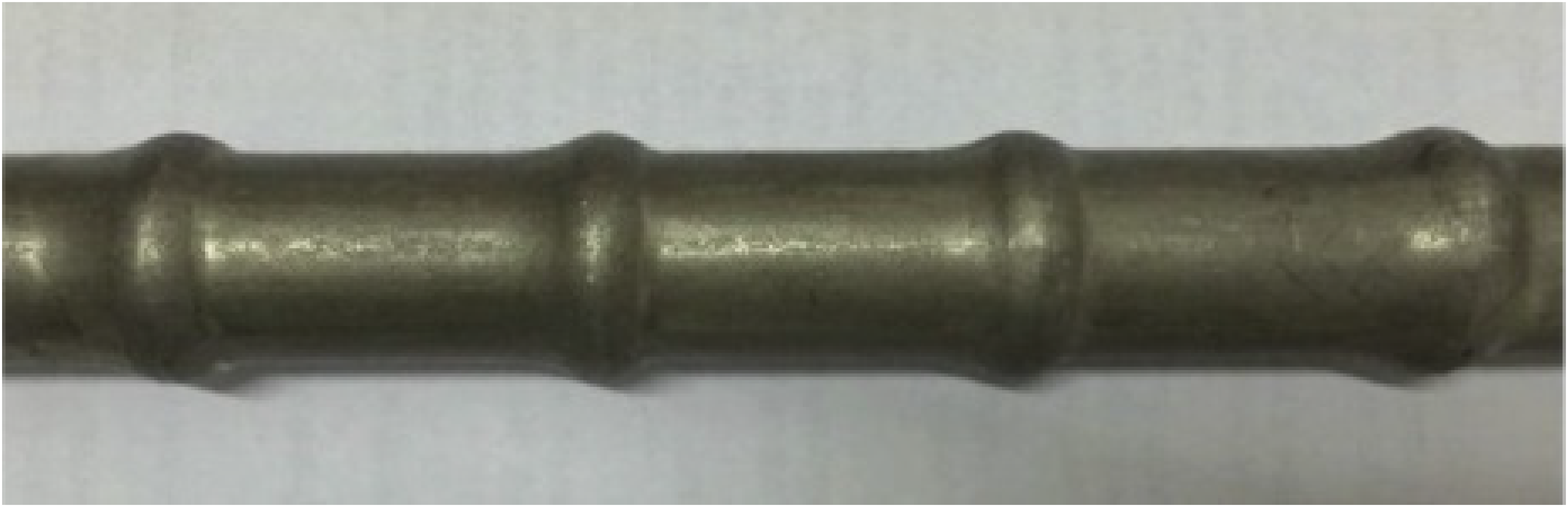
Convex corrugated receiver tube. 97
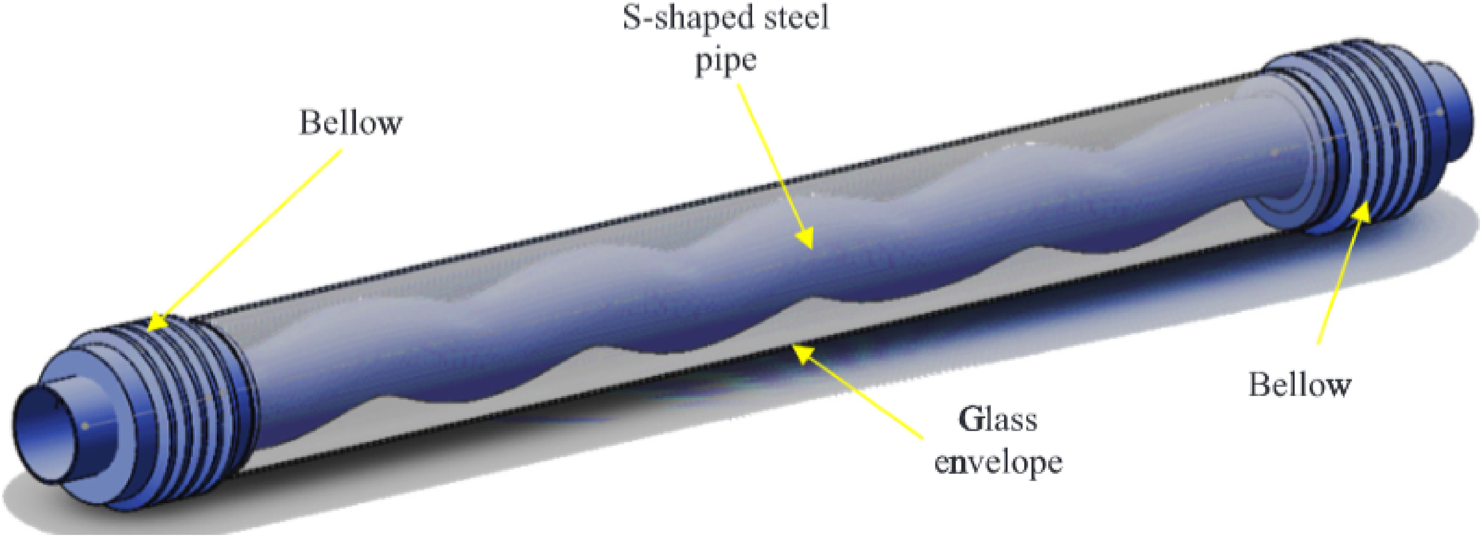
Sinusoidal receiver tube. 107
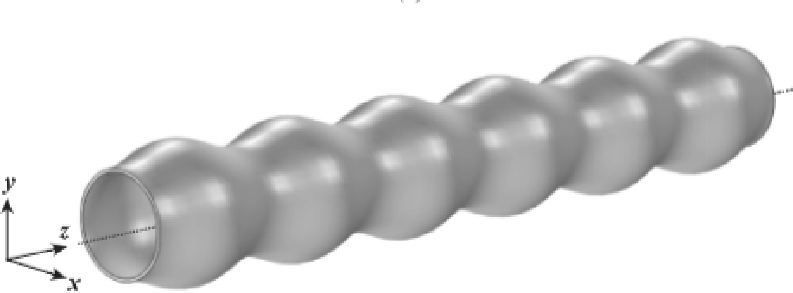
Symmetric wavy receiver tube. 138
Parabolic trough collector with other types of turbulators
The researchers also tried a few other modifications to improve the energy transport process between the heat transfer medium and receiver. Kalidasan et al. 72 developed PTC by attaching one hinged blade in the receiver (Figure 23). The revised receiver tube with hinged blades provided a thermal efficiency of 69.33% to that of 60.82% observed for a conventional receiver. The performance analysis of PTC by taking a few cylinders in the receiver tube is reported by Bellos et al. 71 The orientation of cylinders in the collector tube is depicted in Figure 24. The improvement of heat transfer coefficient was a few times larger than the amount of improvement in thermal efficiency. Consideration of a larger number of cylinder inserts led to better larger efficiency and pump work. As shown in Figure 25, the innovation of star-shaped insert in the tube of PTC and the exploration was done by Bellos and Tzivanidis. 66 The investigation showed that the increment in heat transfer coefficient and Nusselt number was almost 60%. These increments caused a decline in thermal losses of 14%. The required pumping work was too low (16 W) to that of the effective heat gained (25 kW) in all the investigated models. It was observed that the optimum star insert was one with fins of 5 mm thickness. The optimal span of fin for star insert was 20 to 30 mm. One linear cavity with the shape of an arc on the receiver with one lunette channel behind the cavity is investigated by Li et al. 100 It is suggested that the right width of aperture for such receiver should be around 50 to 70 mm after taking into account heat losses. The use of non-Newtonian fluid with a U-shaped collector tube (Figure 26) is numerically evaluated by Yan et al. 141 The highest thermal efficiency of 43.1% is obtained for Re of 5000 when a U-shaped tube was used. The optimal Re for maximum energy efficiency was noted as 5000. For all the values of Re, energy efficiency in the dual-pass tube was better than that of the single-pass tube. Thermal diffusion for liquid reduced in collector tube of higher diameter. A computational study for a V-grooved collector tube with Al2O3-based water nanofluid as a liquid medium was performed by Biswakarma et al. 142 The study took three varying heat fluxes (600–1000 W/m2) and two varying Re values of 6000 and 4000, and a 13.8% improvement in heat transfer coefficient was noticed using nanoparticles with maximum concentration. An experimental evaluation by considering rotating collector tubes was performed by Norouzi et al. 143 The outcomes of the analysis indicated that the optimum range of the rotating speed caused it to regulate and decrease the receiver temperature by 60%. Besides, the efficiency of the collector increased by 17.5% for rotating collector tubes.
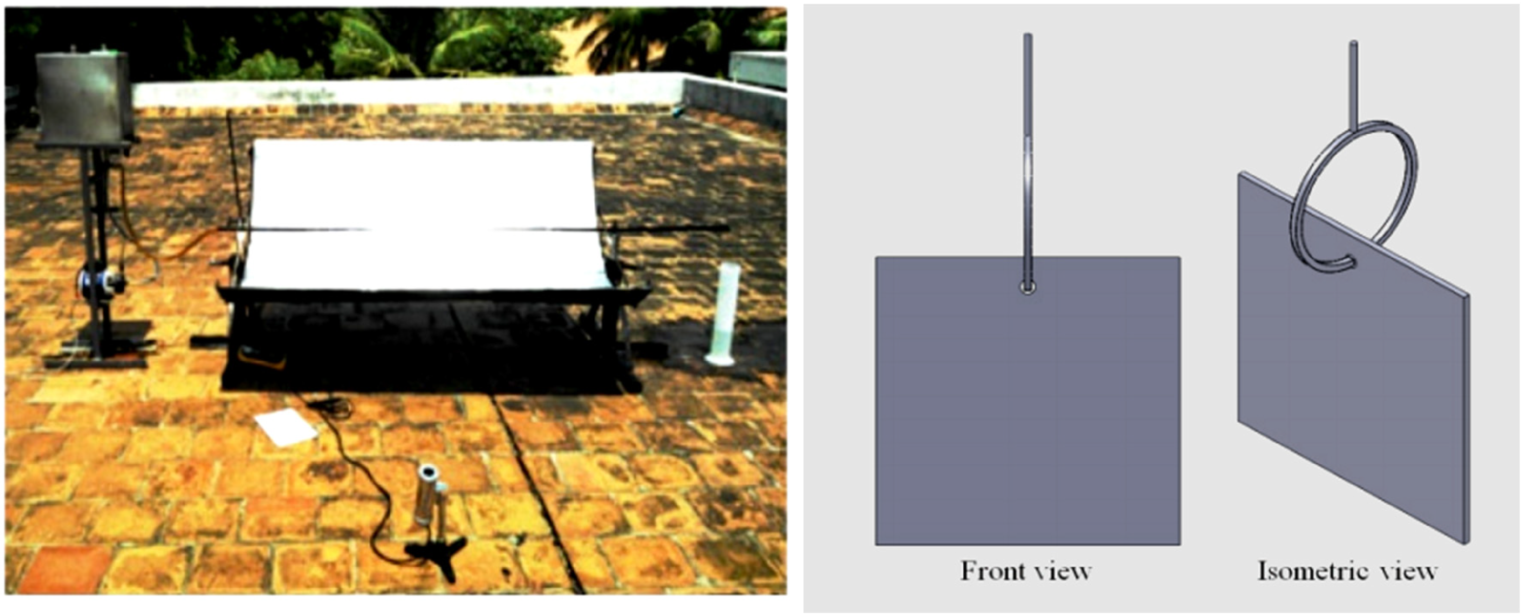
Experimental setup for hinged blade insert. 72

Cylinder insert in receiver tube of PTC. 71
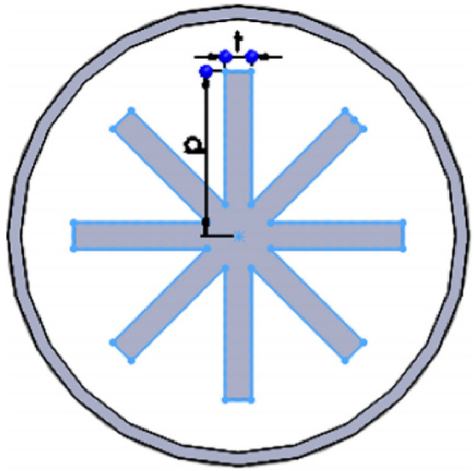
Star insert in receiver tube. 66

U-shaped tube for parabolic trough collector. 141
PTC based on different types of nanofluid
In the past, besides the geometry modifications, many attempts have been made to augment the heat transfer phenomenon with the inclusion of nanoparticles into working fluids. Nanofluids are mostly simple extension of normal liquid medium by addition of particles of small size—particles with minimum of one dimension in-between 1 to 100 nm. After the noticeable investigation conducted by Choi, 144 nanofluids were firstly tested for their capacity to increase the thermal conductivity of heat carrying medium. Nanofluids were examined for their capability to enhance the thermal and physical parameters like thermal diffusivity, density, convective heat transfer, viscosity, and specific heat capacity. Nanofluids were observed to evince for improved thermophysical changes better than the base liquid due to: (a) better intrinsic properties of the presence of small particles (because of their concentration and morphology), (b) because of the movement of nanoparticles in the liquid, or (c) because of the interaction among other particle and liquid, creates a nanolayer or intersection layer.145–149 In case of solar energy demands, it was observed that nanoparticles can be engaged as selective absorbing and broadband absorbers. 150
Numerical analysis of Ghasemi and Ranjbar 36 demonstrated an increment in heat transfer coefficient of receiver tube by 28% as well as 35% for Al2O3 and CuO nanoparticles in water, respectively. In similar work of Bellos and Tzivanidis, 47 it is seen that observed that efficiency of collector tube increased by 1.26% and 1.13% for CuO/water and Al2O3/water based nanofluid, respectively. Bellos et al. 151 considered PTC for Syltherm 800/Cu as HTF in the case of three varying types of the collector tube system. The evaluation indicated, by taking a bare receiver cover, the maximum improvement of thermal losses was noted to be 7.16%. For the nonevacuated collector, the highest increment was 4.87% and 4.06% in the evacuated collector at 25 l/m with a cermet coating. Fathabadi 152 used CuO mixed water for 1% volume concentration in a two-phase closed thermosiphon heat pipe experimentally, and reported highest thermal efficiency of 76.3% in comparison to flat pate (74.9%) and evacuated tube solar collector (71.6%).
Hatami et al. 153 suggested that Cu nanoparticle is most suitable for PTC application than the Fe3O4, Al2O3, and TiO2. Mwesigye et al. 67 pointed an enhancement in thermal efficiency of PTC by 4.4% with single-walled carbon nanotubes-Therminol VP-1 nanofluid. Rehan et al. 154 reported that Al2O3-based nanofluid resulted in better thermal performance compared to Fe2O3. Malekan et al. 155 found that Fe3O4/Therminol 66 nanofluid is a better option than CuO/Therminol 66 nanofluids in order to increase collector. In other studies of Subramani et al.,156,157 thermal efficiency improved by 8.66% and 8.54% for TiO2 and Al2O3 based nanofluid, respectively. A numerical investigation of Mwesigye et al. 158 suggested the improvement in the performance by choosing Slytherm 800/Al2O3 nanofluid, which was around 7.6%. Kasaeian et al. 159 draw a conclusion that the utilization of oil/multiwalled carbon nanotube (MWCNT) improved thermal efficiency by 17% in comparison to base fluid performance. Recently, consideration of hybrid nanofluids has become most popular, and in similar direction, Bellos and Tzivanidis 47 noted that Syltherm 800/(Al2O3-TiO2) improved the performance by around 1.8%, whereas single nanofluid caused the increment by almost 0.7%.
Bellos and Tzivanidis 160 studied the influence of nanofluids and nanoparticle concentration on the thermal changes of PTC. They reported that out of different oxide-based nanofluids, CuO showed higher thermal efficiency enhancement (Figure 27). They also identified that thermal efficiency enhancement is maximum with highest concentration of nanoparticles (till 6%). A PTC was modeled and constructed for experimental testing of the global efficiency of the collector by Kasaeian et al., 161 considering nanoparticles of MWCNT in oil as the heat conveying liquid. The examinations were conducted for 0.2% and 0.3% vol. fraction of nanoparticles in base liquid. The outcomes indicate that the global efficiency of vacuumed receiver is 11% better than the bare receiver efficiency. Akhijahani et al. 162 tested experimentally the thermal and economical changes of dried slices of Rhubarb along with PTC for mechanism of air recycling. Al2O3 of 3.75% concentration was used as heat conveying liquid. The overall efficiency of drying enhanced by 2.32–8.21%. Al2O3 and graphene oxide (GO) in distilled water as heat conveying medium for trough collector was taken and tested experimentally by Hosseini et al. 163 for 2% vol. fraction. The best improvement in terms of thermal efficiency was found as 63.2% for GO nanofluid as well as 32.1% for Al2O3 nanofluid at 1L/min. The thermal changes of a flat plate solar receiver by taking Fe3O4 and MWCNT nanoparticles in distilled water as heat conveying liquid was tested by Said et al. 164 Table 5 summarizes the thermophysical properties for nanofluids considered in various research studies, whereas improvement in performance of PTC using various nanofluids is presented in Figure 28. Hence, it is noteworthy that the effectiveness of PTC can be enhanced by taking nanofluids as HTF. Simultaneously, due to agglomeration related to nanoparticles in the liquid flow, the performance was noted to be affected the cost related with nanofluid was also comparatively high.
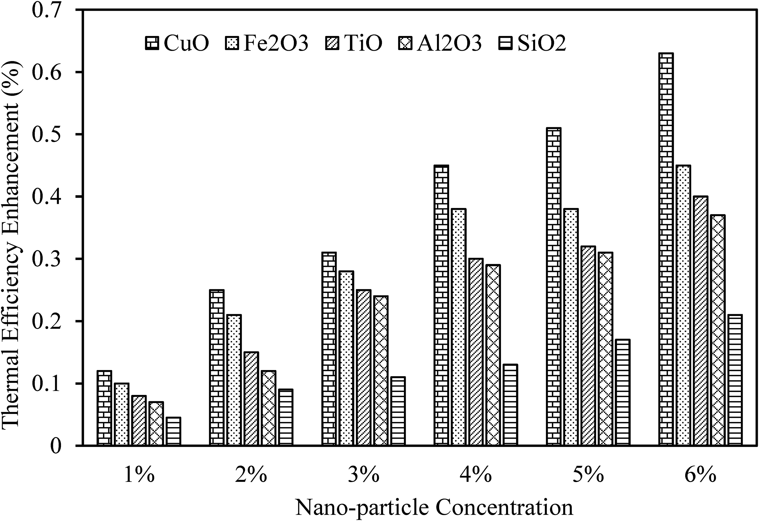
Effect of nanoparticle concentration on the thermal efficiency enhancement of PTC for different nanofluids (inlet temperature = 600 K and flow rate 150 L/min). 160
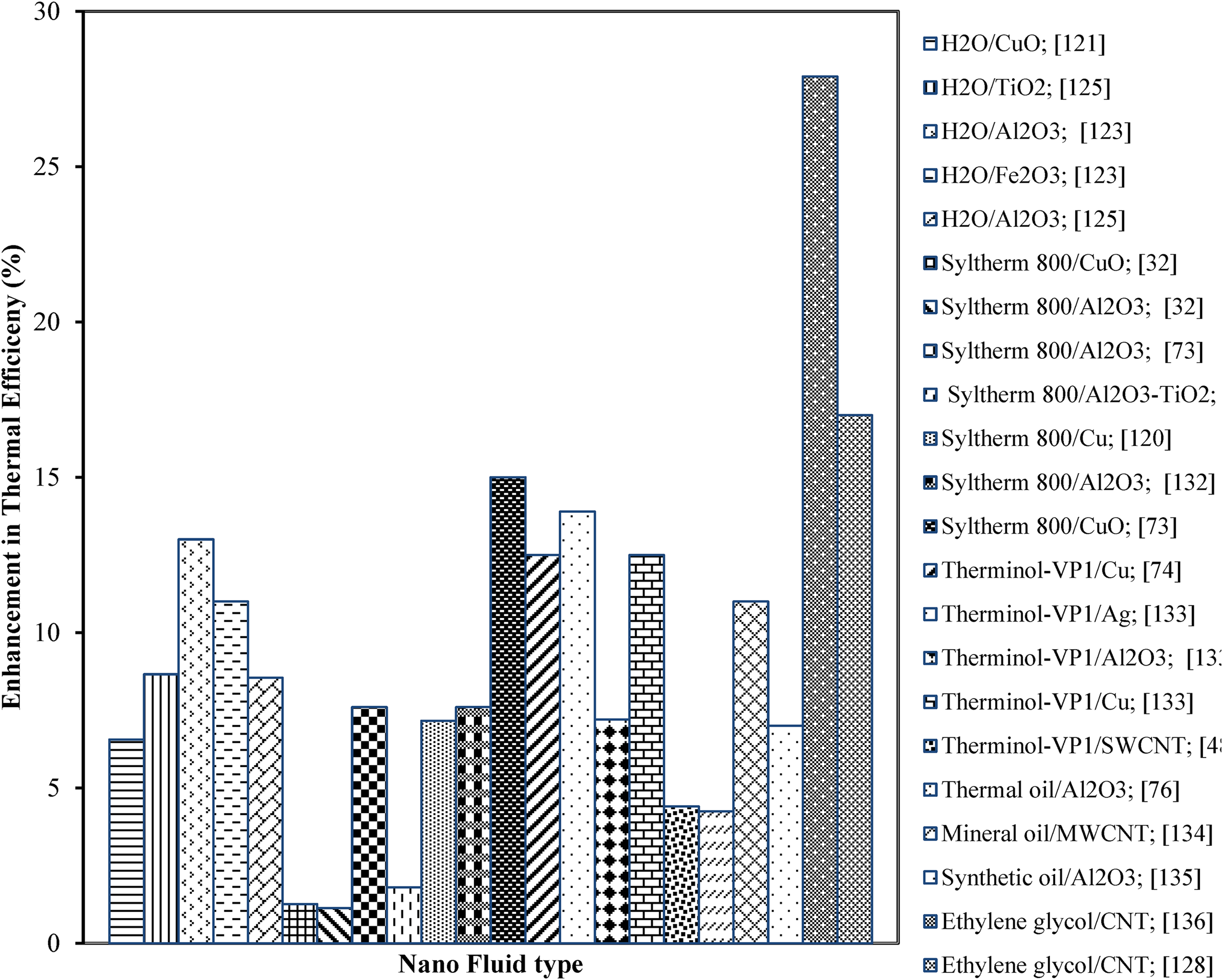
Effect of nanofluids on the thermal efficiency of PTC using water, syltherm, therminol, thermal, mineral, synthetic, and ethylene glycol as base fluids.

PTC: parabolic trough collector.
It is observed that the consideration of nanofluids in PTCs can potentially enhance their efficiency and performance. However, the practicality and scalability of applying nanofluids in PTC depend on several factors that need to be considered, are highlighted below.
Stability
The production and stability of nanofluids can be complex and expensive. The nanoparticles need to be properly dispersed and stabilized within the base fluid, which can require additional processing steps and may introduce challenges in terms of maintaining long-term stability. 165
Cost
Nanofluids can be more expensive to manufacture than conventional fluids. The cost of nanoparticles as well as the additional processing steps needed to make stable nanofluids can have an impact on the technology's overall cost-effectiveness. However, certain pre-made nanofluids are also on the market for their cost-effective use in commercial applications. 166
Safety and environmental considerations
The potential health and environmental impacts of nanofluids should be carefully evaluated. While many nanoparticles are considered safe, their long-term effects and potential risks need to be thoroughly assessed before widespread implementation. For example, silver nanoparticles were found to create short-term and long-term toxicity to human body, entering to blood through inhalation, ingestion, and intraoral–peritoneal injection.167–169
Nanoparticle availability
The scalability of nanofluid-based PTCs is dependent on the cost-effective and reliable supply of nanoparticles. Scalability may be limited if the demand for nanoparticles exceeds the supply or if the cost becomes unsustainable at bigger scales. The number of firms producing nanofluids for industrial uses is expanding, and various patents on the creation of stable and commercial nanofluids have been submitted.169–171 As a result, the viability of using nanoparticles is growing.
System integration
Implementing nanofluids in PTCs may require modifications to the existing systems and infrastructure. The compatibility of nanofluids with the materials used in the collector's components, such as pipes and heat exchangers, needs to be considered. However, there is very less information about the characteristics of nanofluids in bends, pumps, valves, flow meters, filters, sensor, valves, calibrated orifices, etc. 165
Long-term performance and maintenance
The long-term performance and maintenance requirements of nanofluid-based systems should be evaluated. Factors such as nanoparticle deposition or fouling within the collector's components and the potential for decreased heat transfer efficiency over time need to be monitored and addressed. 165
Techno-economic and environmental analysis of PTC
Techno-economic analysis
Recent improvements in PTC systems will lead to enhancement of plant performance by reducing the thermal and optical losses. 172 Undoubtedly, two primary measures to assess a PTC plant are its performance and cost. The overall costs for generation of electric power by the PTC systems are mainly dependent on four major elements: the capital cost of equipment, the performance of the system, the operating condition, as well as maintenance costs. 173 The size of the plant is also one of the major factor in order to reduce the overall installation and operation cost. 174 It is observed that increasing the plant size, the capital cost can be reduced significantly. 175 The specific cost for a PTC with 40 MW can be reduced by 28% at 160 MW, 176 and 12.1% by doubling the plant size of 50 MW. 175 Mokheimer et al. 177 found that specific cost for a 10 MW PTC plant can be dropped by 61% at 160 MW, by 48% at 80 MW, by 37% at 40 MW, and by 19% at 20 MW. It is pertinent to mention that specific cost for a PTC field per unit aperture area as well as specific cost of various mechanical works can be reduced by almost 46% and 48% at 10 hectares and by almost 72% and 75% at 160 hectares, respectively, than at 2.8 hectares while the civil cost of the plant will be maintained constant. It is worth noting that the ratio of the cost to area of field is correlated for areas under 60 hectares, after wards slope of decrement becomes insignificant. Hence, this is suggested to have PTC field size of 60 hectares or bigger. 177 Further, Aseri et al. 175 have stated that while the unit capital cost for CSP plants is noted to be in the range of US$ 3850 to 10,000 per kW, the corresponding values for solar PV plants are US$ 950 to 1250 per kW as well as for coal plants are US$ 3000 to 8400 per kW. In Table 6, a summary of the technical and unit cost of PTC plants is listed.
Technical and unit cost of some parabolic trough based CSP plants across the world. 175

CSP: concentrated solar power.
Economic feasibility of implementing PTCs at a large scale
Employing PTCs at a large scale for solar thermal power production can have both economic benefits and challenges. The economic viability of such an application depends on many aspects, including local conditions, project scale, technology progresses, and policy support. 178 Here are some concerns explained below.
Cost of installation
The initial investment required for large-scale PTC projects is reasonably high. It includes the cost of parabolic collectors, mirrors, support structures, heat transfer fluids, thermal storage systems, and power generation apparatus. The overall estimated capital cost may be higher than $100 million. 179 However, economies of scale and advancements in technology have led to a decrease in costs over the years.
Operational and maintenance costs
PTCs require regular maintenance to confirm optimal performance. This includes cleaning the mirrors, changing components, monitoring and repairing leaks, and handling heat transfer fluids. The economic viability depends on the operational and maintenance costs, which can vary depending on the project size, place, and local labor costs. According to Ritter et al. 180 the average annual maintenance cost a small-scale PTC plant was noted to be around $457/kWe.
Solar resource accessibility
PTCs require ample solar radiation to generate heat and produce electricity efficiently. The economic feasibility depends on the solar resource accessibility at the project location. Areas with high Direct Normal Irradiance (DNI) as high as 2750 kWh/m²/year are more appropriate for setting up of PTC compared to low DNI of 1600 kWh/m²/year.181,182 Performing a detailed solar resource valuation is crucial to determine the project's economic feasibility.
Power generation and revenue
PTCs produce thermal energy that can be transformed into electricity taking steam turbines or other power generation know how. The economic feasibility depends on the electricity generation capacity and the potential revenue from selling the produced electricity. Factors such as local electricity market conditions, power purchase agreements, feed-in tariffs, and government incentives can ominously impact the project's financial viability. For example, Kuraymat PTC plant in Egypt has the total solar aperture area of 130,800 m2 and expected electricity formation of 34,000 MWh/year. 183 If the average electricity price is $50/MWh, 184 then the annual revenue from the plant would be $1.7 million.
Policy and incentive support
Government policies, incentives, and supervisory outlines play a vital role in defining the economic feasibility of large-scale PTC operations. Helpful policies, such as tax credits, grants, feed-in tariffs (FiT), and renewable energy goals can considerably improve the financial viability of projects and appeal investment. For example, FiT rule in Florida allows a range of $0.15/kWh to $0.21/kWh for solar energy depending on the size along with the type of a system. 185
Along with these points, integrating energy storage systems, such as molten salt storage or thermal storage, can enhance the economic viability of PTC projects. Storage systems for electricity allow power generation during nonsunny periods or peak demand hours. Effective grid integration and access to transmission arrangement are also important for ensuring a stable revenue stream.
Environmental analysis
Greenhouse gas (GHG) emissions are noticeably linked with energy utilization and have collected more visibility due to the growing public interest in climatic change. 186 GHG releases (expressed in the form of CO2-eq.) were the most employed index to communicate the CSP plants with environmental impacts associated. Viebahn et al. 187 reported that emissions of GHG from current (solar only operated) CSP systems have better performance (31 g CO2-eq./kWh) than advanced fossil-fired systems (130–900 CO2-eq./kWhel), which could further be decreased to 18 g CO2-eq./kWh in 2050. Burkhardt et al. 188 investigated a wet-cooled, 103 MW plant and concluded that during 30 years life cycle of this plant, almost 26 g CO2-eq./kWh while a dry-cooling during its 30 years life cycle is predicted to discharge 26 g CO2-eq./kWh. Klein and Rubi 189 have stated that for a 110 MW electricity generation, about 60 g CO2-eq./kWh will be emitted. Corona et al. 190 have reported that a 50 MW plant can emit about 26.6 g CO2-eq./kWh during its 25 years life cycle, and with regard to a life span of 30 years, it will produce almost 22 g of CO2-eq./kWh. Furthermore, Mahlangu and Thopil 191 have reported that 100 MW electricity generation will be considered for a life span of 20 years. Climate change found for an estimated 32.2 g CO2-eq./kWh of electricity produced. In addition, Aseri et al. 192 have found that a plant with a 50 MW electricity generation capacity, approximately 22.6 to 22.7 gCO2-eq./kWh with dry-cooling and 18.9 to 19.0 gCO2-eq./kWh with wet-cooling will be emitted to the environment. Life-cycle CO2 emissions of solar-only CSP plants are predicted to be 17 g/kWh in comparison to level of plants working on natural gas (396 g/kWh) and coal (776 g/kWh). 188
Benefits of PTCs for developing regions with limited access to traditional energy sources
PTCs offer several possible benefits for developing countries or areas with inadequate access to traditional energy sources, as explained below.
Renewable and clean energy
PTCs use solar energy, a renewable source that is ample in many developing countries. By using the sun's heat to generate electricity, PTCs provide a clean and viable energy solution. If a 50 MW nominal capacity PTC-based solar thermal power 175 runs at 25% capacity factor, 199 then the plant will produce 1,09,500 MWh of energy per year. They produce no direct emissions during operation, thereby reducing reliance on mitigating environmental pollution, fossil fuels, and GHG emissions. 200
Off-grid and remote uses
PTCs can be mostly beneficial for off-grid or remote areas where grid extension may be challenging or cost-prohibitive. By allowing a decentralized energy solution, PTCs permit electricity access in remote societies, providing essential services such as healthcare facilities, schools, water pumping, and agricultural practices. If an average household consumes 3000 kWh/year, 201 then a PTC plant of a 1,09,500 MWh capacity can power around 36,500 households. This helps bridge the energy access gap as well as enables socio-economic growth in remote regions.
Environmental and health welfares
The use of PTCs pays to reduce air pollution as well as greenhouse gas releases to that of conventional energy sources. If the fossil fuel-based power generation emits 0.6 metric tons of CO2 per MWh, 202 than a PTC plant producing 1,09,500 MWh of energy per year can save about 65,700 metric tons of CO2 emissions per year. This has positive effects for ecological viability and public health.
Lower energy costs
In the regions with limited access to traditional energy sources, PTCs can help improve the load of high energy costs. Once connected, the operational costs of PTCs are fairly low to that of fossil fuel-based power tariffs. Thus societies and businesses can profit from cheap and stable energy prices, enhancing their economic affordability and value of life. The levelized costs of electricity produced from different sources are tabulated as follows (Table 7).
Along with these, PTCs offer numerous other potential benefits namely energy freedom and safety, scalability and flexible design, job creation and local economic growth for developing regions with limited access to conventional energy sources. However, it is crucial to study the specific context, resource availability, local policies, financing mechanisms, and community engagement for successful execution. An inclusive assessment of the social, economic, and environmental features is needed to maximize the positive impact of PTC projects in these regions.

LCOE: levelized costs of electricity; PTC: parabolic trough collector.
Techno-economic and environmental limitations of PTC
PTCs have been widely used and proven to be advantageous in generating eco-friendly energy, but they also have certain limitations and drawbacks, as mentioned below:
Due to heat losses, inaccurate sun tracking, and dirt or dust accumulation on the mirrors, PTC's actual efficiency is lower than its theoretical efficiency. This constraint implies that a portion of the solar energy entering the unit is not efficiently collected and transformed into usable heat.
206
The cost of manufacturing and installing PTCs might be high. The requirement for a tracking system to maintain the mirrors’ alignment with the sun also adds to the capital cost. PTCs might be less financially viable than other renewable energy technologies as a result of their expensive initial investment.
188
PTCs are generally relied on the presence of sunshine. Unless energy storage or backup devices are used, the intermittent nature of solar energy can make it difficult to supply continuous and consistent energy demands.
207
In order to maintain maximum functioning, PTCs need routine maintenance. To keep the mirrors functioning properly, they must be cleaned frequently to remove dust and other dirt. The mechanical parts, including the tracking system, might also need to be repaired or replaced at some point. Thus, the total cost of the PTC system increases considering maintenance and durability.
208
Large areas of land are often required for PTCs to accommodate the parabolic-shaped reflectors and associated equipment. The demand for land can be a considerable disadvantage, particularly in densely populated places or areas with little available land.
209
Installing large-scale solar projects in ecologically sensitive areas such as forests or wetlands can fragment wildlife habitats by creating barriers that limit the movement of animals. This fragmentation can hinder the migration patterns and dispersal abilities of certain species, potentially affecting their population dynamics and genetic diversity.
210
The operation of PTC involves the utilization of mirrors and concentrated sunlight to generate heat. Birds and insects may be attracted to the bright and reflective surfaces, leading to collisions or burns.
211
However, it's worth noting that research has shown that the overall impact on wildlife is relatively low compared to other human-made structures, such as buildings or communication towers. The construction and maintenance of parabolic trough installations can result in soil compaction, erosion, and vegetation removal. These activities may disrupt the local ecosystem and affect the availability of food and shelter for wildlife species.
212
Choosing appropriate locations for solar trough installations, such as already disturbed or nonecologically sensitive areas, can minimize habitat destruction.
213
Conducting thorough environmental impact assessments prior to construction can help identify and mitigate potential risks to wildlife and habitat.
214
Incorporating wildlife-friendly design features into the project, such as incorporating wildlife corridors or creating alternative habitats nearby, can help mitigate the impact on local wildlife populations.
215
Continuous monitoring and research on the ecological impacts of PTCs can help identify and address any unforeseen negative effects on habitat and wildlife.
206
Besides abovementioned drawbacks and limitations, PTCs also have potential negative impacts on habitat and wildlife. A few points are mentioned below:
It's worth noting that compared to other forms of energy generation, such as fossil fuel power plants, PTCs generally have lower long-term negative environmental impacts. However, it's essential to carefully evaluate and manage the potential risks to minimize adverse effects on local wildlife and their habitats. To mitigate the potential negative effects, developers can take certain measures:
Utilization of PTC for different purposes
The various applications of PTCs are presented in Table 8. The outlet temperature for different values of aperture area and solar intensity are summarized in Figures 29 and 30. Ullah and Kang 216 demonstrated the use of PTC for drying process of apples. The performance in the form of the temperature of the drier, moisture loss, efficiency, relative humidity, and drying time were investigated. Moreover, the higher mean efficiency was 23% for the collector tube's smaller collector diameter value of about 5.08 cm. The minimum efficiency was 19.6% at 3.50 kg/min as well as 1.5 kg/min flow rate of air. Panahi et al. 217 had designed a prototype, manufactured, and examined for integrated collector storage in the solar water heater (SWH) and PTC. PTC was also considered in air conditioning operation, analyzed by Bi et al., 218 and highest Coefficient of Performance (COP) noted for a day was 1.5 times. This study was performed experimentally, including design, manufacturing, and testing for a prototype integrated with a collector storage system for the SWH and compound parabolic concentrator. The analyzed system was aimed to produce hot water in case of domestic use for remote rural areas. Six months experimental testing was performed to obtain the thermal behavioral changes for the system. The outcomes showed that mirrors had an enhanced mean daily efficiency (66.7%) compared to aluminum foil (43.7%) and steel (47.6%), respectively.
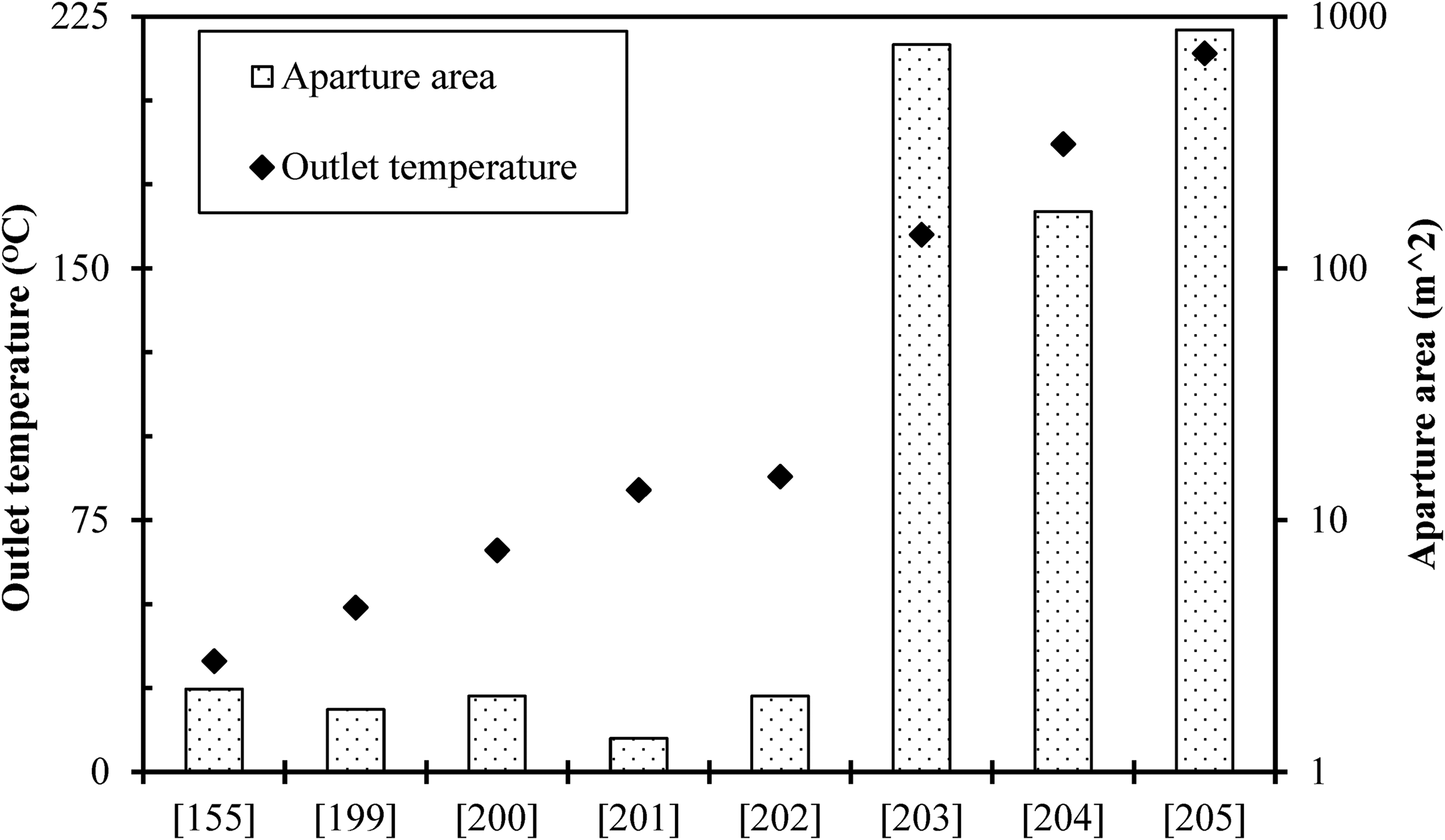
Variation of outlet temperature with aperture area of PTC.

Variation of outlet temperature in PTC with solar intensity.
Summary of various applications of PTCs.

CSP: concentrated solar power; LCOE: levelized costs of electricity; LEC: Levelized Cost of Energy; LFC: Load Frequency Controller; PTC: parabolic trough collector.
Hassine and Pietruschka 219 studied the effect of hardware-in-the-loop test bench (HiL) considered along with a medium-scale PTC. The 122.4m² plant was able to heat water for a steam boiler in the meat industry in Austria. Various test cycles were performed and emulated for critical operation scenarios, for example, collector loop overheating in the test bench. Proper fault detection of the strategy was considered, which one was able to minimize the risk related to enhanced plant availability and component damage. The consideration of PTCs in food-processing industry is to preserve the vegetables was studied by Silva et al. 220 The plant was situated in the Southern part of Spain and required saturated steam for 7 bar for annual consumption of 148MWh. The configuration for the base solar plant was studied by taking PTC solar field, a steam producer and thermally stratified energy storage. The effect of processing parameters of the plant, that is, the outlet temperature of solar field and return temperature of steam generator,was considered to determine their effects in main design indicators of plant. Again, the utility preheater before steam generator was also investigated. The outcomes of innovation indicated that suitability ofchanging energy input schemes for the industry.
Comparison between the PTCs, wind power, and hydroelectric power
It's important to note that the suitability and economic viability of each sustainable energy source vary depending on specific regional factors, such as resource availability, local policies, infrastructure requirements, and grid integration considerations. Evaluating the most appropriate energy source involves a comprehensive analysis of these factors. An explicit comparison between PTC and other sustainable energy sources, such as hydroelectric power and wind is tabulated as follows (Table 9).

PTC: parabolic trough collector.
Polygeneration system with PTC
In recent years, units with multiple outputs have drawn increased attention in the field of energy systems due to their higher overall efficiency. When the number of outputs is three or more, the system is called as polygeneration system.
222
Figure 31 depicts a general schematic of polygeneration system using solar energy as driving energy. The primary objective of polygeneration is to generate all the beneficial outcomes that consumers require in order to build sustainable, compact, effective, and financially feasible energy units. The energy efficiency criteria are typically used in the evaluation of polygeneration systems. The ratio of the useful output energy to the input energy summary is used to define these indices. For example, the energy efficiency (ηen) of a polygeneration (trigeneration) unit with heating production 
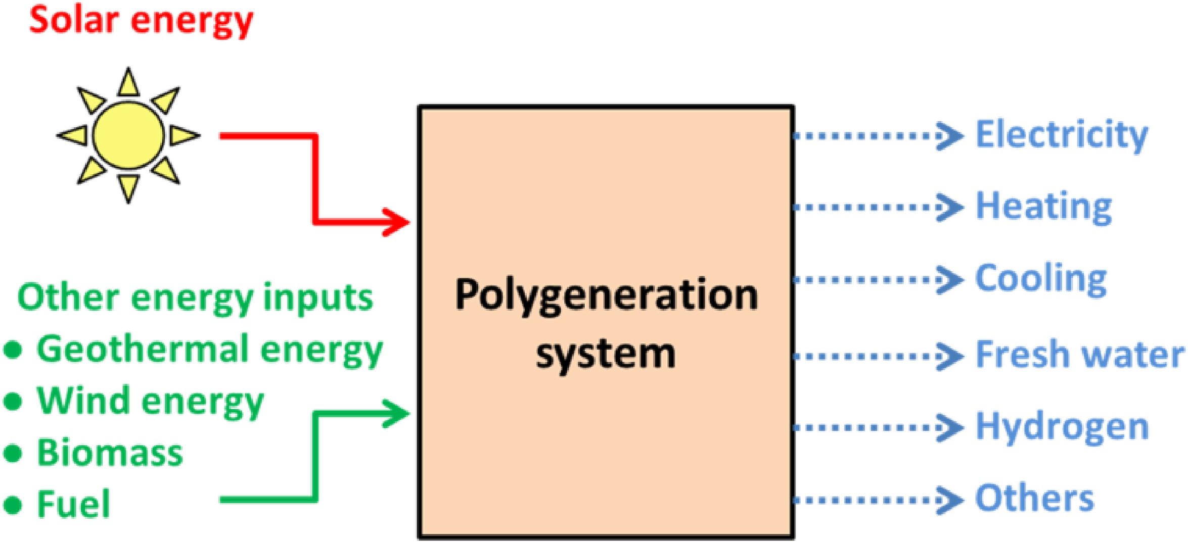
General depiction of a polygeneration system with inputs and outputs. 222
Sahoo et al. 223 have examined a polygeneration unit using solar and biomass energy together. They examined an arrangement for cooling, electricity, and fresh water as shown in Figure 32. In this arrangement, biomass and solar energy are combined to create useable heat in a steam/water Rankine cycle that then feeds an absorption chiller to produce cooling. The final step in this design is a distillation unit that is fed by the heat produced in absorption device. This application's overall energy efficiency was found to be 49.4%, with 20.9% energy efficiency. One polygeneration unit was suggested by Rabeti et al. 224 to generate heat, power, hydrogen-depending, and freshwater on solar energy (by using PTC) and biomass. In this examination, organic Rankine cycle, the Kalina cycle, double-pressure steam cycle, and gas turbine cycle were considered to generate power, multi-influencing desalination as well as reverse osmosis were considered to generate freshwater, and the PEM (proton exchange membrane) electrolyzer was used for hydrogen formation. Again, the exhaust syngas formed from the process of gasification was considered to provide steam for the gasifier reactor. The overall outcomes of the 4E investigation for Municipal solid waste fuel showed that the exergy efficiency and overall energy of the polygeneration unit were 32.01% and 39%, respectively. One PTC driven-polygeneration energy unit along with electrical energy storage was suggested and examined by Rostami et al. 225 The cycle power production unit was comprised of proton-exchange membrane fuel cell, PTC field, thermoelectric generator, organic Rankine cycle, and alkaline electrolyzer. Evidence of the outcomes showed that the suggested polygeneration unit was able of producing 22.5 kW of power. One trigeneration unit for heat, water and power situated in the Qeshm Island was proposed by Modabberet al. 226 The multi-objective process of optimization was conducted to amplify the exergy efficiency and to decrease the environmental and cost influence of the outcomes of the unit. Investigating the unit integrated with the solar thermal collector field had achieved an improvement of 4.77% in terms of efficiency of the unit. Khalid and Kumar 227 assessed a PTC-based polygeneration unit to meet the daily requirement of a residential society of 250 members. They used the unit to produce fresh water, electricity, hydrogen, and cooling. They found the energy efficiency of the unit to be 17.5%. Table 10 summarized various investigations performed in polygeneration system with PTC.
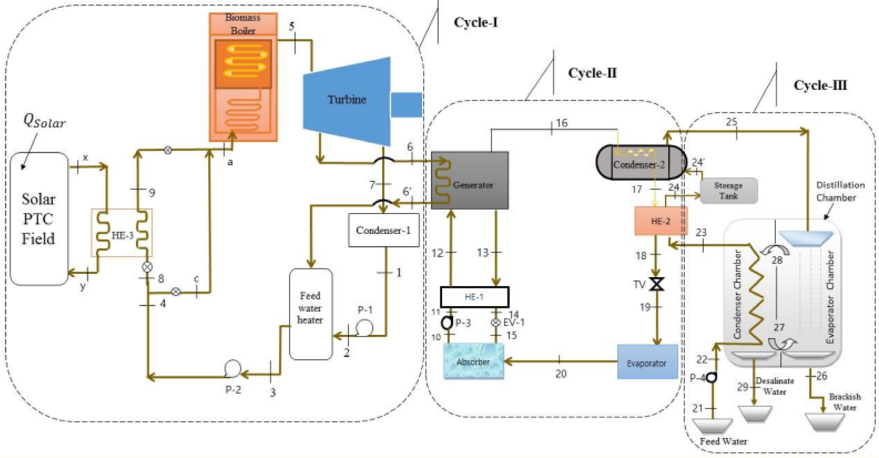
A polygeneration system with PTC. 223
Polygeneration systems with PTCs.

ACH: absorption chiller; ORC: organic Rankine cycle.
Conclusions
Possible performance improvements of PTCs have been reviewed. Based on this review, the performance of PTC could be augmented by increasing surface area of the inner collector tube and improving convective heat transfer coefficient of working fluid. The article showed different methods to increase inner surface area of collector. A comparative conclusion drawn on effects of various types of insert on friction factor and Nusselt number is shown in Table 11. The major outcomes drawn from this discussion are:
Wire coil inserts improved the thermal changes of PTC by around 183% when compared to PTC without inserts. Fitting coiled wire led to a rise in 36.5% in thermal efficiency of PTC when the flow was flowing at 3858 Re with a certain wire thickness and pitch ratio. Wavy-tape inserts improved the Nusselt number maximum upto 261–310% when using Syltherm 800 as working fluid in PTC. Inserting porous twisted tube in collector tube could lead to about 340% increase in Nusselt number, which resulted in about 59% increase in thermal changes of PTC. Extending the inner surface area of the collector could be achieved by installing inserts in the collector as well as using fins, twisted tubes, U-shaped tubes, and porous twisted-shaped tape inserts, and coiled wire inserts caused a substantial enhancement in the heat transfer characteristics. Using nanofluids as HTFs in collector tube could improve the convective heat transfer coefficient. The concentration volume of nanofluid played asignificant role in improving thermal behavior of collector flow. Cu nanoparticles in HTF canimprove Nusselt number, Rayleigh number, and Darcy number. Moreover, the review study pointed that using Al2O3water-based nanofluid could enhance the PTC thermal efficiency by 8.5%.
Comparison of different types of inserts.

Pertinent literature indicates that the study of PTC performance still needs more attentionin coming future to extract more useful energy from PTC; hence this study recommends the following for future work:
Design parameters of PTC should be thoroughly investigated, including its optical parameters. More emphasis is required on enhancing the thermal and optical efficiency of a PTC by selective coating as well as auto-tracking systems. Modification of collector profile and surface area, such as convergent-divergent tubes with dimples, internally finned tubes with various fin profiles, etc., can be studied for higher heat transfer and lower pressure drop. Conventional receiver tube of PTC can be equipped with different-shaped spinning inserts along with different types of nanofluid to achieve better thermal performance. Synthesis and examination of economical and high thermal conductivity nanofluid by taking the morphology of nanoparticles need proper attention. The research conducted till date is focused more on aqueous nanofluids than oil-based nanofluids. Hence, further investigation on oil-based nanofluids is essential to precisely study their thermohydraulic behavior in the PTC system. A detailed investigation is to be performed on the utilization of phase change material-based hybrid nanoparticles inside the PTC. Not many research works have been performed considering ionic fluid nanofluids; this sector could also be studied. Most of the hybrid nanofluids as working medium for PTC are obtained by blending two types of nanoparticles it can be done for three or four types of nanoparticles in base liquid to get better thermal changes. Due to a large number of parameters, artificial intelligence methods should be implemented to predict the optimum parameters leading to the best possible PTC performance.
Footnotes
Declaration of conflicting interests
The authors declared no potential conflicts of interest with respect to the research, authorship, and/or publication of this article.
Funding
The authors received no financial support for the research, authorship, and/or publication of this article.
