
Abstract
Background
Titanium (Ti) and polyether ether ketone (PEEK) interbody fusion cages cause postoperative stress shielding problems. The porous cage design is one of the solutions advanced to mitigate this problem.
Objective
Exploring the mitigation of stress shielding with a porous interbody fusion cage after surgery for idiopathic scoliosis.
Methods
The porous interbody fusion cage was constructed based on the multiscale topology optimisation method, and the postoperative lumbar spine models implanted with it. The porous Ti and PEEK fusion cages were evaluated under physiological conditions to investigate their mechanical properties.
Results
The volume of the porous fusion cage was reduced by 52.57%, and the stress was increased by 242.76% and 252.46% compared with the Ti and PEEK fusion cage; the modulus of elasticity of the porous fusion cage was reduced by 76.85%, and the strain was increased by 131.40%∼686.51% compared with the Ti cage; the porous fusion cage increased L3 cortical bone stress by 13.36% and 13.52% and cancellous bone by 82.93% and 76.72%, respectively, compared with the original interbody fusion cages.
Conclusion
The porous interbody fusion cage has a much more lightweight design which facilitates growth of bone tissue. However, a frame structure should be constructed to minimize issues with stress peaks and localised stress concentrations. It also has a significantly lower stiffness which helps alleviate vertebral stress shielding, further fostering bone growth. The porous fusion cage thus meets the clinical requirements for better fusion outcomes.
Keywords
Introduction
Idiopathic scoliosis (IS) is a complex three-dimensional spinal deformity of unknown aetiology. It is characterised by a Cobb angle of >10°. 1 It is predominant in females, with incidence significantly increasing with age. 2 Without early intervention, the disease may exacerbate flexion deformity, thoracic compression, and cause serious cardiopulmonary problems, thus affecting the patient's appearance and health.3,4
Osteotomy and corrective surgery are effective treatments for managing IS, where they help to stop further deformity of the spine, rebuild and restore the patient's overall balance, and improve the patient's quality of life. 5 Interbody fusion cages are medical implants used to accommodate bone grafts and by maintain vertebral stability. They do this by propping up the space between two vertebrae after a damaged disc has been removed and restoring interbody height. 6 They have shown great clinical results and wide used in spinal surgery, making them some of the most common spinal implants in practice.7–9
Presently, most interbody fusion cages are made using titanium alloy (Ti) and polyether ether ketone (PEEK). Cages made from pure titanium and its alloys have good biocompatibility, high strength and corrosion resistance, 10 while those from PEEK are a stable, resistant to corrosion and have an excellent elastic modulus close to that of cortical bone.11,12 The modulus of elasticity of titanium alloys implants is much higher than that of bone and are prone to stress shielding phenomenon which causes them to sink. While the modulus of elasticity of PEEK implants is close to that of cortical bone and thus can help reduce stress shielding, they however exhibits poor biocompatibility and may slow down the osseointegration or lead to displacement. 13 These two materials are mostly used to make intervertebral fusion cages which are more commonly used in spinal surgeries. Although common, the interbody fusion cages have challenges such as stress shielding, subsidence, displacement and local osteolysis.14,15 The focus of scientific research has been on how to improve the intervertebral fusion cage implants so as to reduce the postoperative complications.
One of the methods put forward to solve these problems has been, the construction of porous interbody fusion cages. These cages are gradually becoming the go-to solution because of their low density, large surface area, improved strength and stiffness. The interconnected porous structure of the cages accelerates the transfer of nutrients, 16 which facilitates cell adhesion, proliferation and differentiation, leading to osteointegration 17 thus reducing postoperative complications. Fujibayashi et al 18 designed a personalised porous titanium interbody fusion cage and conducted a clinical trial with it. In the study found that none of the patients implanted with the cage experienced cage subsidence or adverse effects. In a study by McGilvray et al, 19 three types of fusion cages, including porous titanium, were implanted into the lumbar spine of sheep. The results indicate that porous fusion cages had better arthrodesis results. However, porous structures created through traditional Computer-Aided Design methods still faces challenges. Additionally, human complexity, bioethical constraints and other issues make in vivo studies of the mechanical properties of porous fusion cages more difficult to conduct.
Topology optimisation based on finite element methods is a mathematical approach used to develop optimal designs of porous intervertebral fusion cages while adhering to specific constraints. 20 It is carried out at macro and micro scales. The macrotopology optimisation for fusion cages has been shown to reduce implant mass and increase graft space, but then again, it still has the problem of stress shielding. 21 Microtopology optimisation is preferred when constructing porous fusion cages. 16 It involves designing microcells and arranging them to create the porous fusion cage. It also suffers from a number of shortcomings whereby it does not comprehensively take into account the requirements of the patient's bone tissue, and lacks holistic structural design for the porous framework. 22 A multiscale topology optimisation method that takes into account both macrostructure and microstructure, validated and analysed through simulation, can yield porous intervertebral fusion cage with superior mechanical properties.
This study addresses the current research landscape, using IS as an example. A multi-scale topology optimization based on the finite element method was adopted to design and construct personalized porous interbody fusion cage, and constructs Ti and PEEK interbody fusion cages at the same time. Lumbar spine models were established to evaluate the three different fusion cages by simulating seven common physiological conditions of the human body – extension, flexion, right lateral bending, right rotation, erect, left lateral bending, and left rotation – to compare their biomechanical properties. The findings were able to provide a scientific basis for the design of intervertebral fusion cage and to inform the development and refinement of IS surgical protocols.
Materials and methods
Establishment of finite element model of deformed lumbar spine
The IS case study presented in this paper was sourced from the Sixth Affiliated Hospital of Xinjiang Medical University. The patients demographics were recorded: a 47-year-old female standing at 140 cm tall and weighing 39 kg, had an upper thoracic curvature of 32°, main thoracic curvature of 67°, thoracolumbar curvature of 40°, and a posterior convexity of 124° while in a standing position. The patient suffered from Lenke4C + scoliosis and required multiple surgical corrections and provided informed consent for participation in the study.
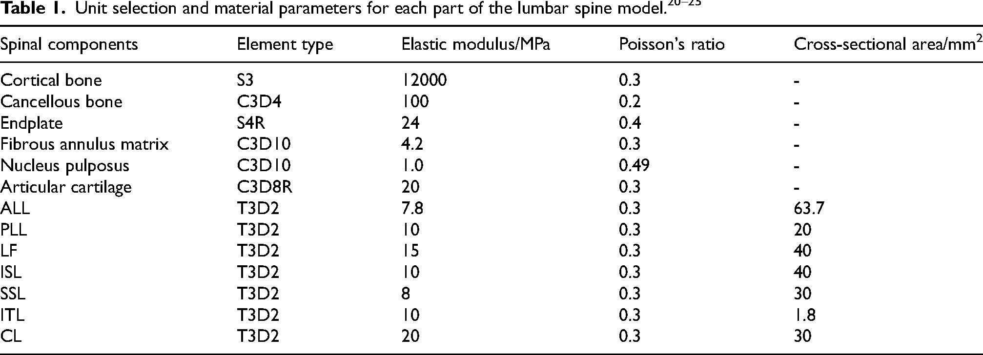
The CT data for the case was imported into Mimics 21.0 (Materialise, Belgium) as a DICOM file, from which a 3D geometric model of the L1-L5 vertebrae was generated through thresholds setting and manual segmentation. This 3D model was imported into Geomagic Studio 12.0 (Geomagic Company, USA) in STL format for fit surface fitting. Further construction of the vertebral cortical bone, vertebral cancellous bone, endplates, annulus fibrosus matrix, nucleus pulposus, articular cartilage, anterior longitudinal ligament (ALL), posterior longitudinal ligament (PLL), ligamentum flavum (LF), capsular ligament (CL), intertransverse ligament (ITL), interspinous ligament (ISL) and supraspinous ligament (SSL), were done in Hypermesh 14.0 (Altair, USA). 23 The fibrous annulus and nucleus pulposus accounted for 56% and 44% of the volume in the intervertebral disc, respectively. 24 Meshing was performed, with the vertebral cortical bone being simulated using a mixture of triangular linear strain shell cells with a thickness of 1 mm. 25 The cancellous bone was modelled using tetrahedral first-order linear solid units, while the endplate was simulated using a rectangular linear strain shell unit. The fibrous ring matrix, medulla and small joints were simulated using a ten-node tetrahedral second-order linear solid unit. The ligaments were put up as linearly elastic isotropic materials and were simulated using a one-dimensional nonlinear rod cell. The L1-L5 deformed lumbar spine model were obtained using the process outlined in Figure 1. The material properties of each structure are detailed in Table 1.
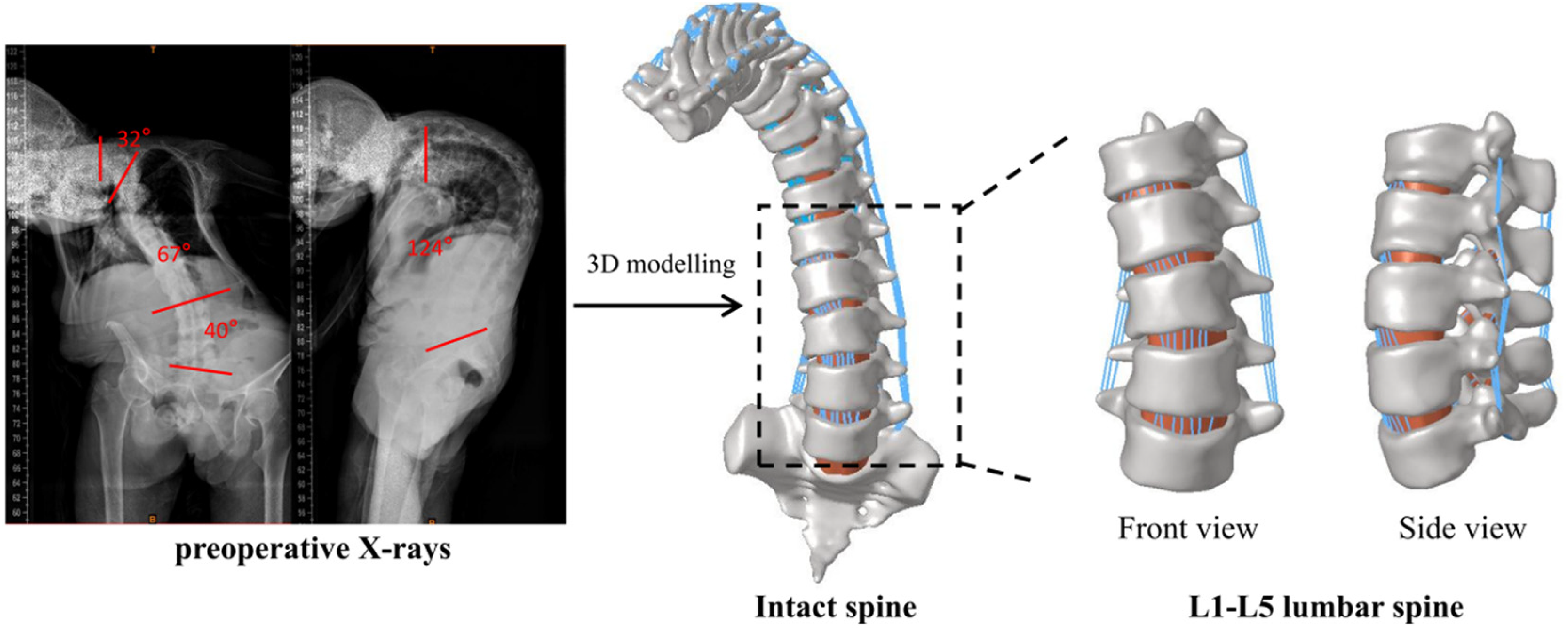
The protocol for establishing the L1-L5 deformed lumbar spine model.
Validation of lumbar spine model validity
The validity of the model was verified using segmented loading experiments. Relatively healthy L4 and L5 segments were selected for validation. A fully fixed constraint was applied to the lower surface of the L5 vertebrae, while axial loads of 500, 1000, 1500, and 2000 N were uniformly applied to the upper surface of the L4 vertebrae. 26 The computed results were compared with the experimental results so as to verify the model's accuracy.
The axial displacements of the vertebrae were measured as follows: 0.30 mm, 0.59 mm, 0.89 mm, and 1.18 mm under uniform axial loads of 500 N, 1000 N, 1500 N, and 2000 N, respectively. The calculated data were plotted into axial load-axial displacement curves as shown in Figure 2. They were then compared with the experimental data of Shahraki, 27 Kim, 28 Markolf 29 and Brown. 30 The results of the ex vivo experiments were matched to the results of the finite element analysis of the L4-L5 vertebrae under similar conditions, and the errors checked whether they were within a reasonable range, had the same growth trend, so as to verify the reliability and validity of the model.
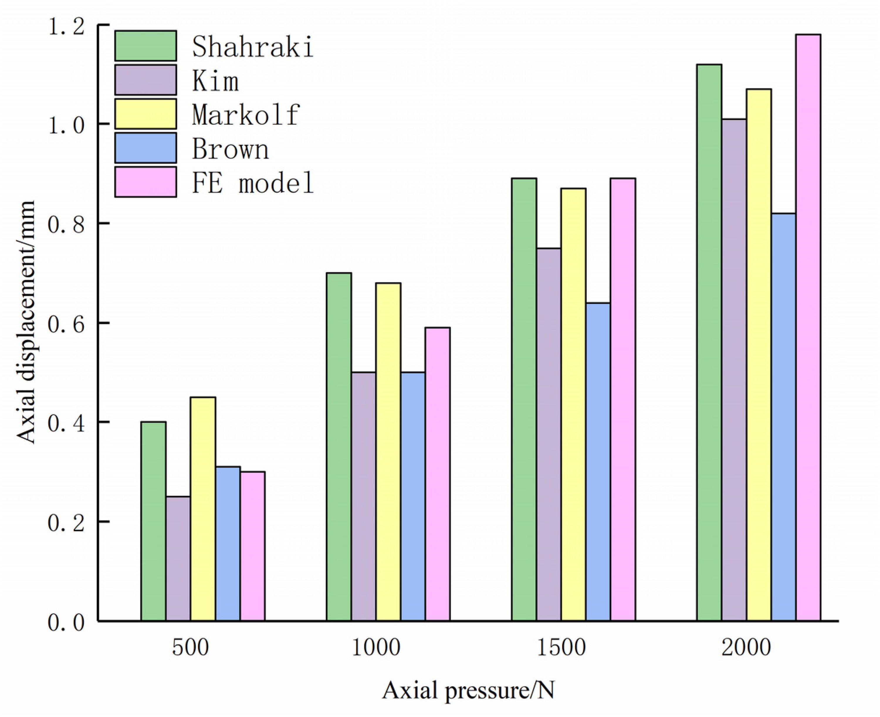
Axial displacement curve for the vertebral body under different uniform pressures.
Finite element modelling after deformed lumbar osteotomy
The doctors at the University proposed a lumbar spine correction surgical plan, integrating advances in osteotomy surgery from both domestic and international practices. The procedure involved revealing the posterior spinal structures, nailing the segments as follows: the left L1-L2 vertebrae and the L4 and L5 vertebrae; the right L1-L2 vertebrae and the L4-L5 vertebrae. Osteotomies were performed at the L3 vertebrae and an interbody fusion cage was implanted to correct for scoliosis and kyphosis deformities of the lumbar spine. A concave side connecting bar was placed to stabilise adjacent screws and another convex side connecting bar was used to close adjacent screws.
The lumbar scoliosis angle was reduced from 40° to 13.21°, and the kyphosis angle was reduced from 32° to 3.39°. Postoperative indicators, including thoracolumbar curvature, number of osteotomies, osteotomy difficulty, and structure of the fixation system to evaluate the effectiveness of the surgical protocol.
Simulations of the osteotomy plan were done in Solidworks 2022 (Dassault Systemes, USA) and the initial personalised fusion cage and nail bar system constructed. The mesh was then delineated and material properties assigned in Hypermesh 14.0 (Altair, USA) with the nail rod system being made of Ti (E = 110,000 MPa, v = 0.3). Finally, the fusion cage and the nail rod system were bound to the lumbar spine model in ABAQUS 6.14 (Dassault Inc., USA). The osteotomy correction process and the lumbar spine model post-osteotomy are shown in Figure 3.
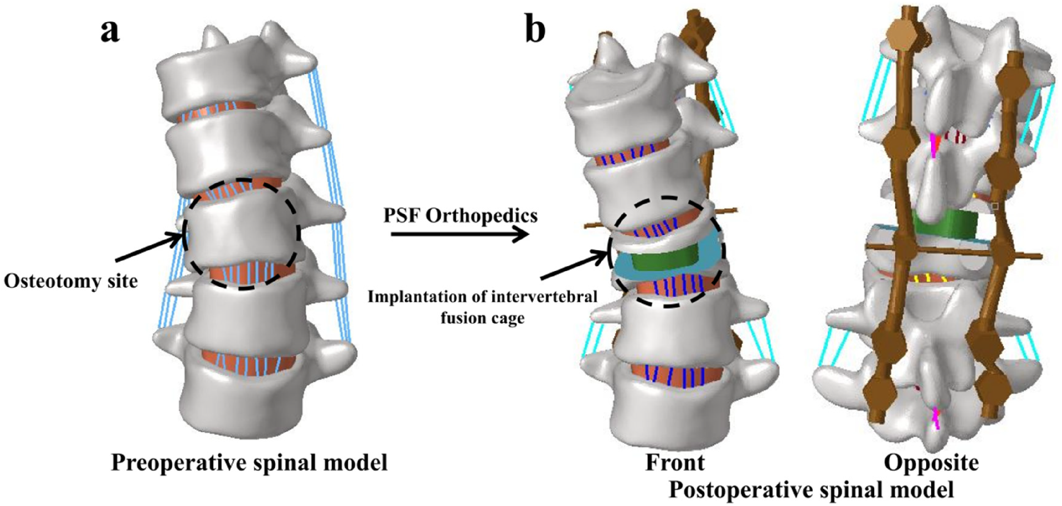
The procedure of lumbar osteotomy correction (a) Preoperative spinal model (b) Postoperative spinal model.
Fusion cage microscale topology optimisation
To obtain the microcells – the arrays of porous structures composing the Porous interbody fusion cages – with the least flexibility, density-based topology optimisation of the Ti material cell body (1 mm × 1 mm × 1 mm) was done in Optistruct (Altair, USA). This optimisation used a constrained volume fraction of 0.3, resulting in a porosity of 0.7, which is an ideal pore size for growth of bone tissue.
31
To account for the compressive loads experienced by the implanted intervertebral fusion cage after surgery,
16
a simplification was made during the optimisation process, where a loading pattern was applied to the unit. The unit was fixed to the centre of the bottom surface, and a force of 1 N applied to the centres of the remaining five surfaces, to obtain an octahedral-structured micro-unit, as illustrated in Figure 4(a). The mathematical formulation used in topology optimisation is shown below:


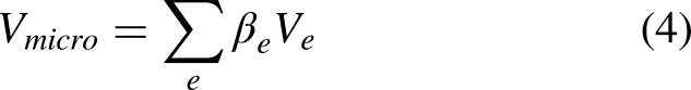

Topological optimization process of micro unit bodies, (a) Unit under compressive load (b) Micro unit volume obtained after optimization, (c) Porous structure constructed from optimized unit bodies.
Where βe is the density variable of the microcells, n is the number of grid cells, Cmicro is the overall flexibility of the microcells, Vmicro is the volume of the microcells, Ve is the volume of the grid cells, V0 is the original volume of the microcells, V* is the volume of the removed microcells, βmin = 0.01.
Under the constraint that the volume does not exceed 30%, the overall flexibility of the microcellular body was minimised and the pore size of the porous structure determined at 600 μm. The designed microcellular and porous structures are shown in Figure 4(b) and (c).
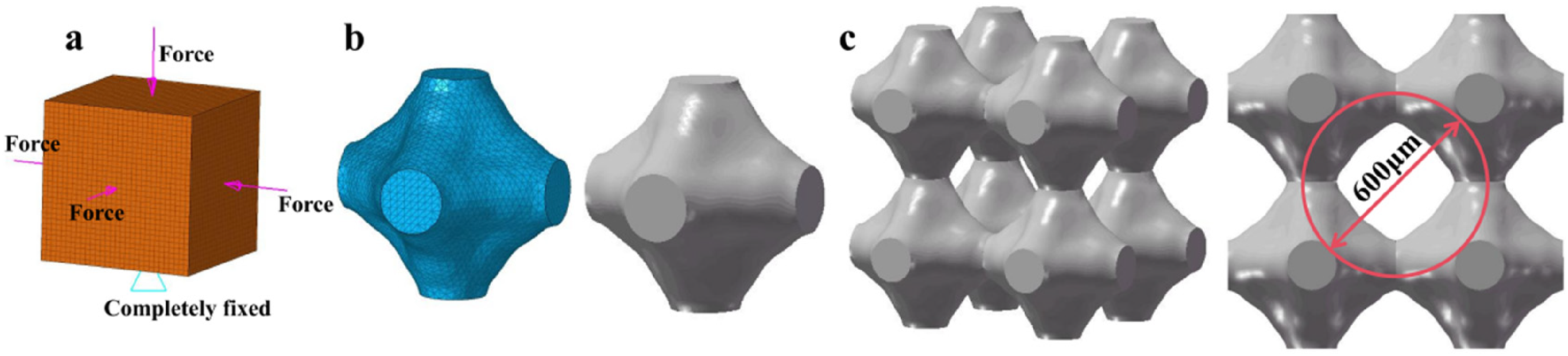
To investigate the mechanical properties of the porous structure, the finite element method was used to simulate the compression of the porous structure. The Ti material was modelled as an ideal elastic-plastic material, with a fatigue stress of 900 MPa and a plastic strain of 0 in the setup plastic phase. 32 A vertical displacement load of 30% of the overall height was applied to the upper surface of the porous structure, while the lower surface was fully restrained, 33 as shown in Figure 5(a). The stress-strain curve, as shown in Figure 5(b), yielded an equivalent modulus of elasticity of 2.547 GPa, and Poisson's ratio of 0.35 was derrived from the axial and transverse strains of the porous structure.
Boundary conditions and finite element analysis results for simulated compression of porous structures, (a) The loads and constraints on porous structures, (b) Stress-strain curve.
Macroscale topology optimisation of fusion cage and porous fusion cage establishment
The mechanical properties of porous structures were obtained by adoption of fusion cages in macro-scale topology optimisation. The implanted fusion cage was subjected to constant axial loads, avoiding stress concentrations in its radial cross-section from sudden changes in the geometrical profile. The cage was also subject to slippage or detachment caused by tangential loads. The optimised loads for the macroscopic topology of the fusion cage were thus focused on the shear loads.
The fusion cage had the same end profile and symmetrical structure. The patient had a uniform frequency of motion for each condition and the fusion cage loads were symmetrical. This simplification allowed the model to be represented as a shell where 1/2 of the structure was be taken for density based optimisation in ABAQUS 6.14 (Dassault Inc., USA).
The loading was done by fixing the symmetry axis of the optimised object completely and applying shear loads at each node so as to minimise flexibility. Intervertebral fusion cages with a volume fraction of 15–30% had optimal biocompatibility.
34
To avoid subsidence caused by too small a contact surface area, the was volume fraction constraint was set at 0.3.
35
The optimization process consisted of 10 labelled iterations. The mathematical formula for topology optimisation used was:


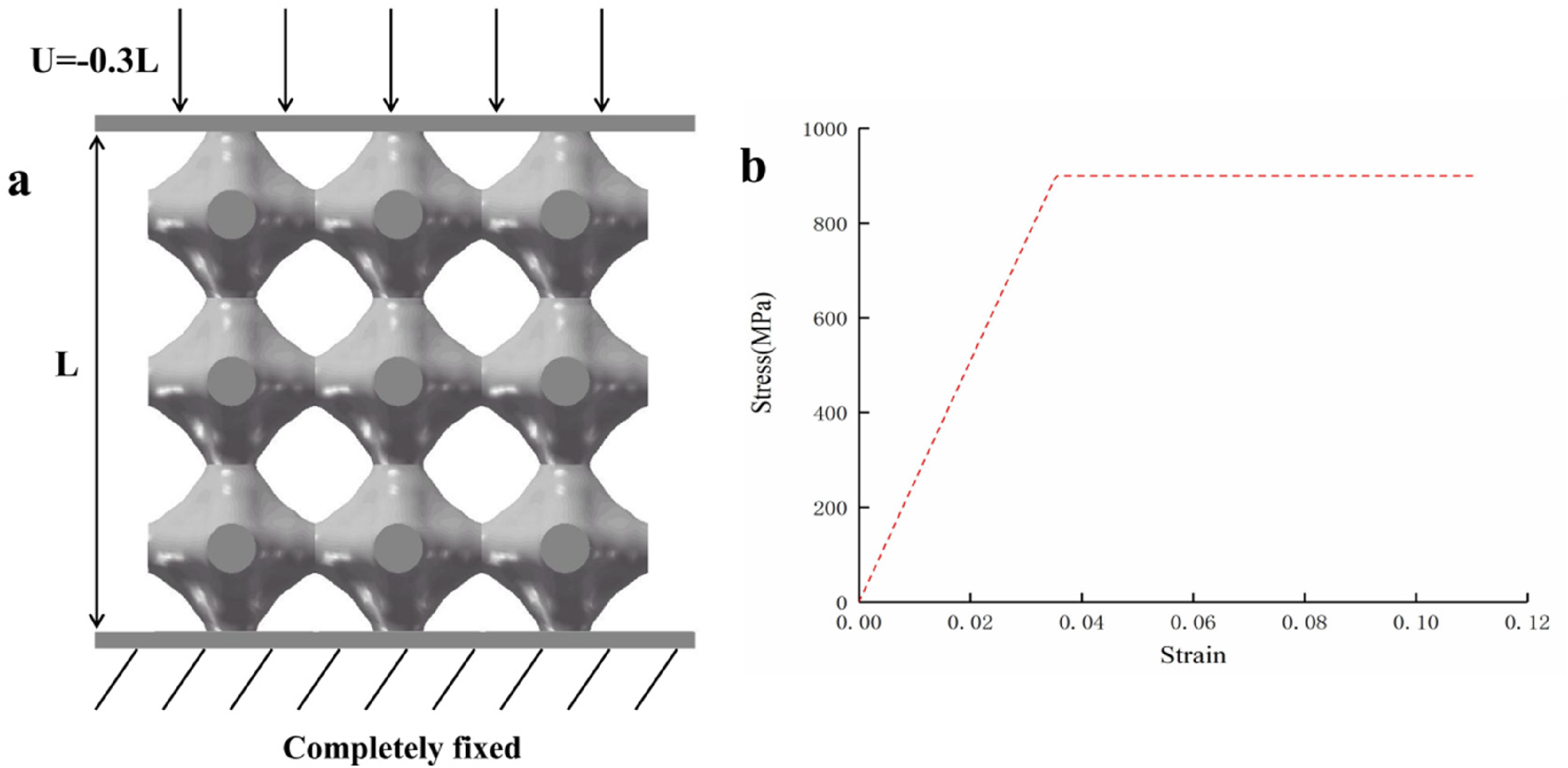
Based on the optimisation results, a curve was fitted to reduce the stress concentration. The fusion cage was redesigned to obtain a solid alternative porous intervertebral fusion cage. The specific steps of the topology optimisation are shown in Figure 6.
Macro topology optimization process, (a) Original personalized fusion device (b)1/2 fusion device (c) The macro topology optimization results of the fusion device, (d) Personalized Fuser after Macro Topology Optimization.
Boundary conditions and constraints
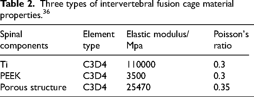
The topology-optimised porous intervertebral fusion cage was compared with the initial personalised fusion cages made of Ti and PEEK material. A finite element model incorporating the placement of these three fusion cages was built on the basis of the deformed lumbar spine model post-osteotomy, as shown in Figure 7 with the material properties of the fusion cages’ shown in Table 2.
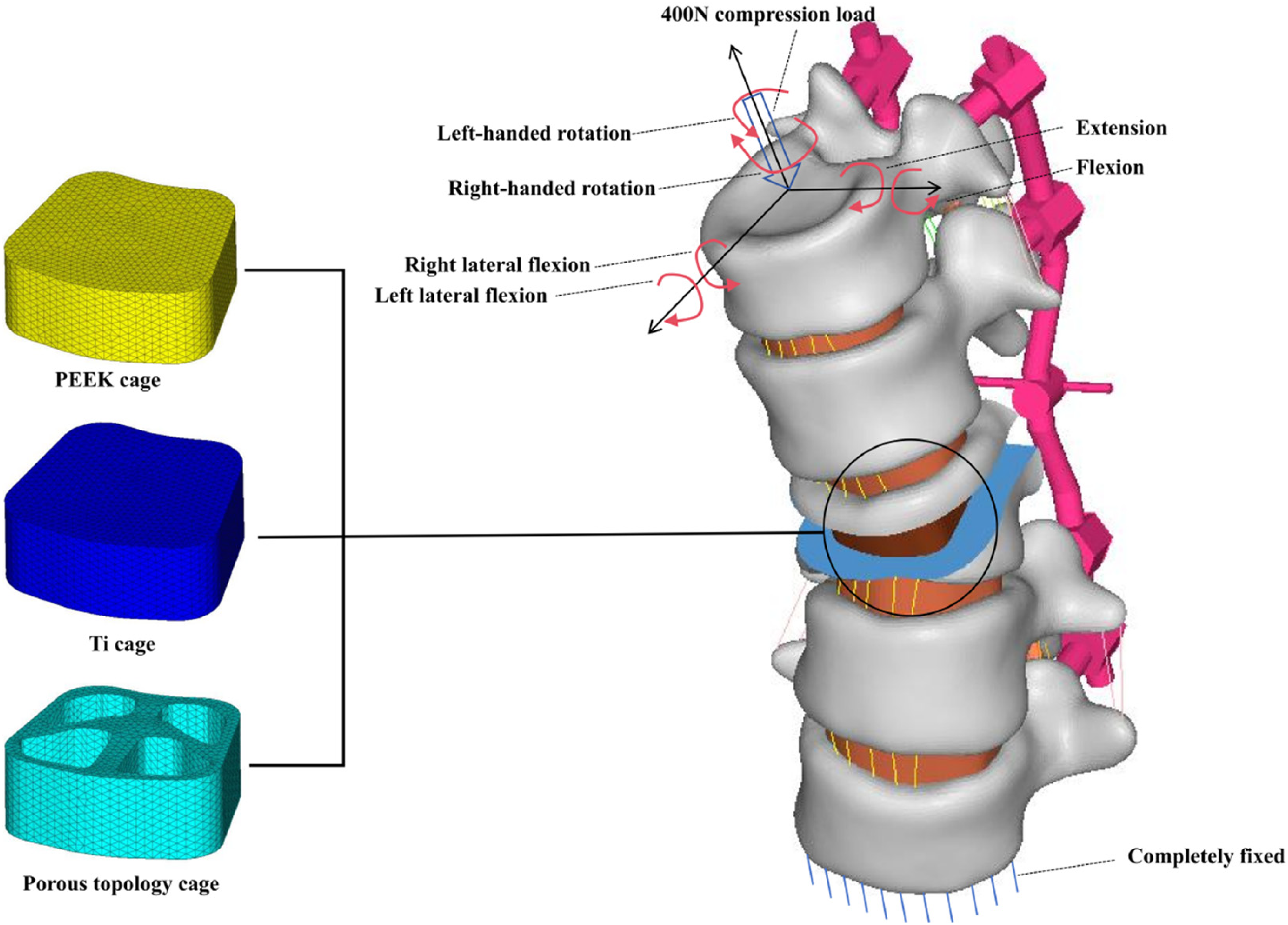
The schematic diagram of three types of fusion cages implanted in the lumbar spine and lumbar spine boundary conditions.
Three types of intervertebral fusion cage material properties. 36
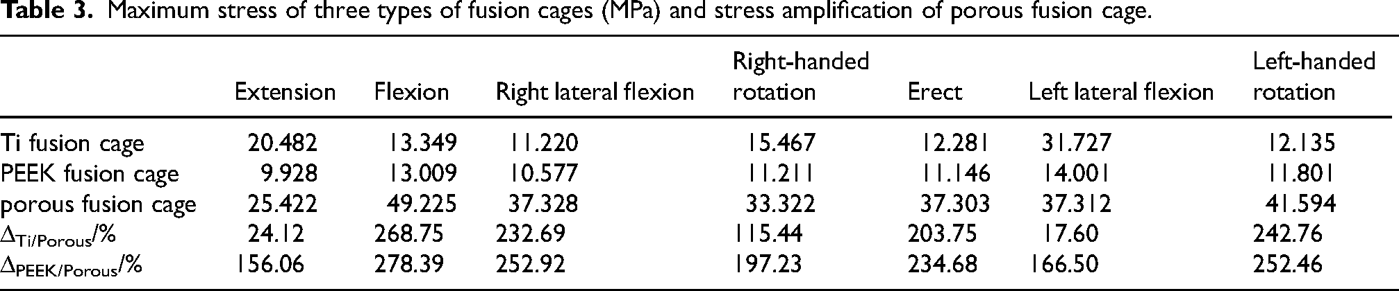
Maximum stress of three types of fusion cages (MPa) and stress amplification of porous fusion cage.
During normal activity, the end surfaces of the spine are not only subjected to normal gravitational forces exerted by adjacent vertebrae, but by other forces caused by various movements. A fully fixed constraint was thus applied to the lower surface of the L5 vertebrae, as shown in Figure 7. A compressive load of 400 N was applied normal to the upper end face of the L1 vertebrae 37 to simulate the force in the upright state. Six moments, each with a magnitude of 3.9 N·m, 38 were also applied to the upper end face to simulate six working conditions, including extension, flexion, right lateral bending, right rotation, erect, left lateral bending, and left rotation with a moment.
Results
Lumbar spine model stress results
The stress distribution of the lumbar spine model implanted with different types of interbody fusion cages is depicted in Figure 8. Under the seven working conditions – extension, flexion, right lateral bending, right rotation, erect, left lateral bending, and left rotation – the maximum stress values observed were as follows: the Ti fusion cage reached its peak stress of 79.950 MPa during extension; the PEEK fusion cage reached its peak stress of 79.100 MPa during flexion; the porous fusion cage reached its peak stress of 84.274 MPa during flexion. All the three lumbar spine models implanted with different fusion cages, achieved the maximum value of lumbar spine stress at the L5 cortical bone, regardless of the working conditions.
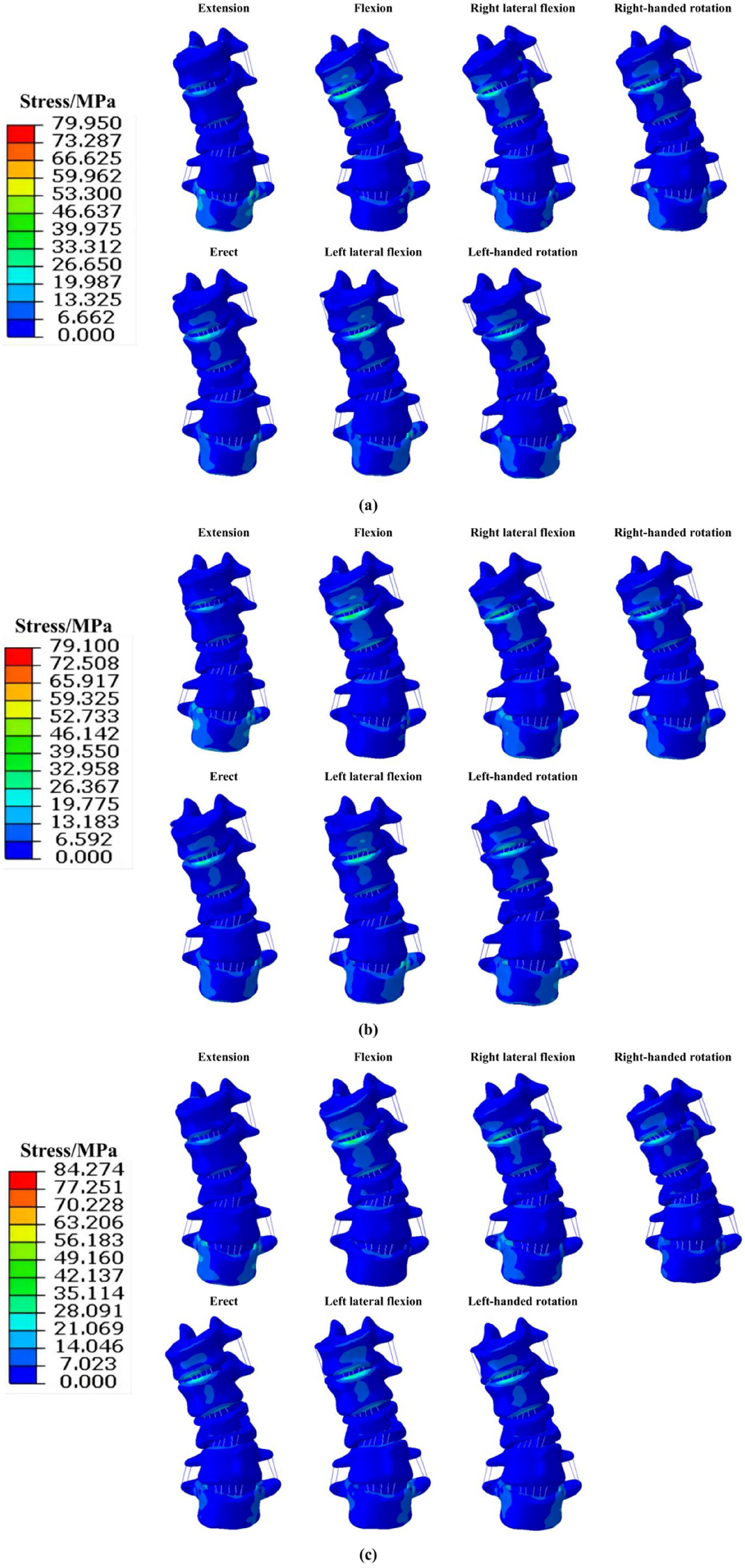
Maximum stress of lumbar vertebrae implanted with different types of intervertebral fusion cages, (a) The maximum stress of lumbar vertebrae implanted with Ti intervertebral fusion cage, (b) Maximum stress of lumbar vertebrae implanted with PEEK intervertebral fusion cage, (c) Maximum stress of lumbar vertebrae implanted with porous intervertebral fusion cage.
Interbody fusion cage stress and strain results
The volume of the intervertebral fusion cage decreased from 5456.32 mm3 to 2587.80 mm3 after optimisation which represents a significant reduction of 52.57%. The stress distribution for the three intervertebral fusion cage models under each working condition is shown in Figure 9, highlighting the peak stress and peak increase, as shown in Table 3. The maximum stress for the Ti and PEEK interbody fusion cage was 31.727 MPa and 14.001 MPa respectively, during the left lateral bending, while the and the maximum stress for the porous interbody fusion cage was 49.225 MPa under the flexion.
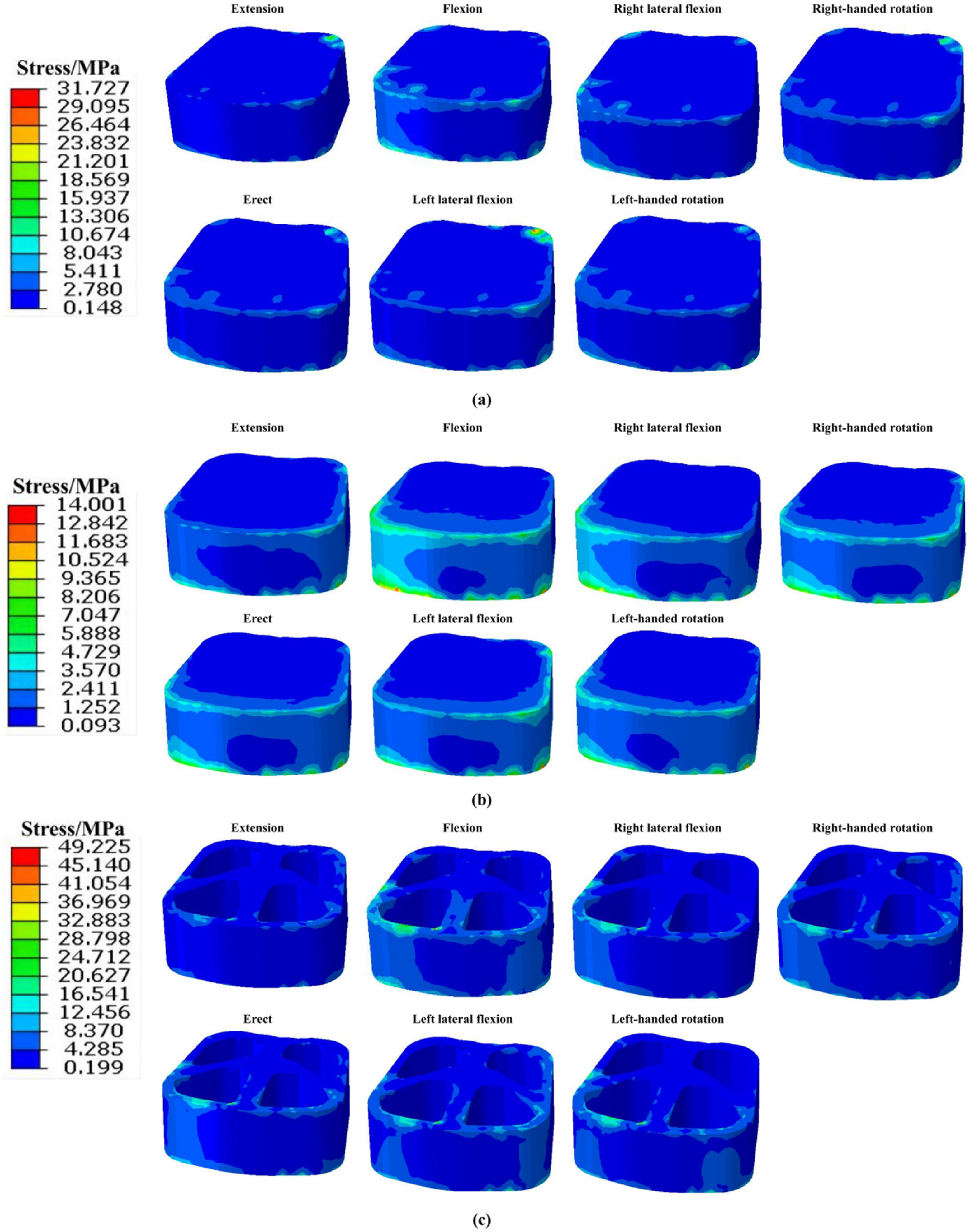
The maximum stress of three types of fusion cages, (a) The maximum stress of Ti fusion cage, (b) Maximum stress of PEEK fusion cage, (c) Maximum stress of porous fusion cage.
Although their stress peaks differed at the seven working conditions, the Ti interbody fusion cage and PEEK interbody fusion cage had similar distributions. When compared with the Ti interbody fusion cage, the peak stress values of the porous interbody fusion cage increased by 24.12%, 268.75%, 232.69%, 115.44%, 203.75%, 17.60%, and 242.76% in the extension, flexion, right lateral bending, right rotation, erect, left lateral bending, and left rotation working conditions, respectively. Similarly compared with the PEEK interbody fusion cage, the maximum stresses of the porous interbody fusion cage increased by 156.06%, 278.39%, 252.92%, 197.23%, 234.68%, 166.50%, and 252.46% in the under the same working conditions, respectively. The peak stresses were mainly found at the inner wall of the porous interbody fusion cage.
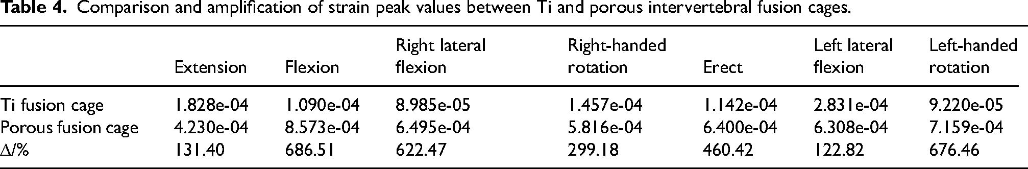
The peak strains and their increase for the Ti and porous interbody fusion cages are presented in Table 4. The peak strains of the Ti interbody fusion cage were 1.828E-04, 1.090E-04, 8.985E-05, 1.457E-04, 1.142E-04, 2.831E-04, and 9.220E-05 for the extension, flexion, right lateral bending, right rotation, erect, left lateral bending, and left rotation working conditions, respectively. The peak strains of the porous interbody fusion cage were 4.230E-04, 8.573E-04, 6.495E-04, 5.816E-04, 6.400E-04, 6.308E-04, and 7.159E-04 in extension, flexion, right lateral bending, right rotation, erect, left lateral bending, and left rotation working conditions, respectively. The peak strain of the porous interbody fusion cage increased by 131.40%, 686.51%, 622.47%, 299.18%, 460.42%, 122.82%, and 676.46% compared with the Ti interbody fusion cage for each working condition, respectively.
Comparison and amplification of strain peak values between Ti and porous intervertebral fusion cages.
L3 vertebral cortical and cancellous bone stress results
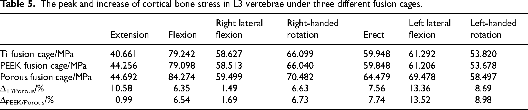
The peak stresses in the L3 vertebral body following the post-implantation of the three types of interbody fusion cages are shown in Figure 10. Regardless of the interbody fusion cage type implanted, the maximum peak stress in the cortical bone in the L3 vertebra was recorded during flexion at 84.274 MPa, while the minimum value was recorded during extension condition at 40.661 MPa. The peak stress in the L3 cortical bone post-implantation of the porous fusion cage was greater than the post-implantation of the Ti and PEEK fusion cages, under all seven working conditions. The Ti and PEEK fusion cages however displayed similar stress values, The specific increases are shown in Table 5. Implantation of the porous interbody fusion cage resulted in a 13.36% and 1.49% maximum and minimum increase of peak respectively, in the L3 cortical bone stress relative to Ti interbody fusion cage. Similarly it resulted in a 13.52% and 0.99% maximum and minimum increase of peak respectively, in the L3 cortical bone stress relative to the PEEK interbody fusion cage.
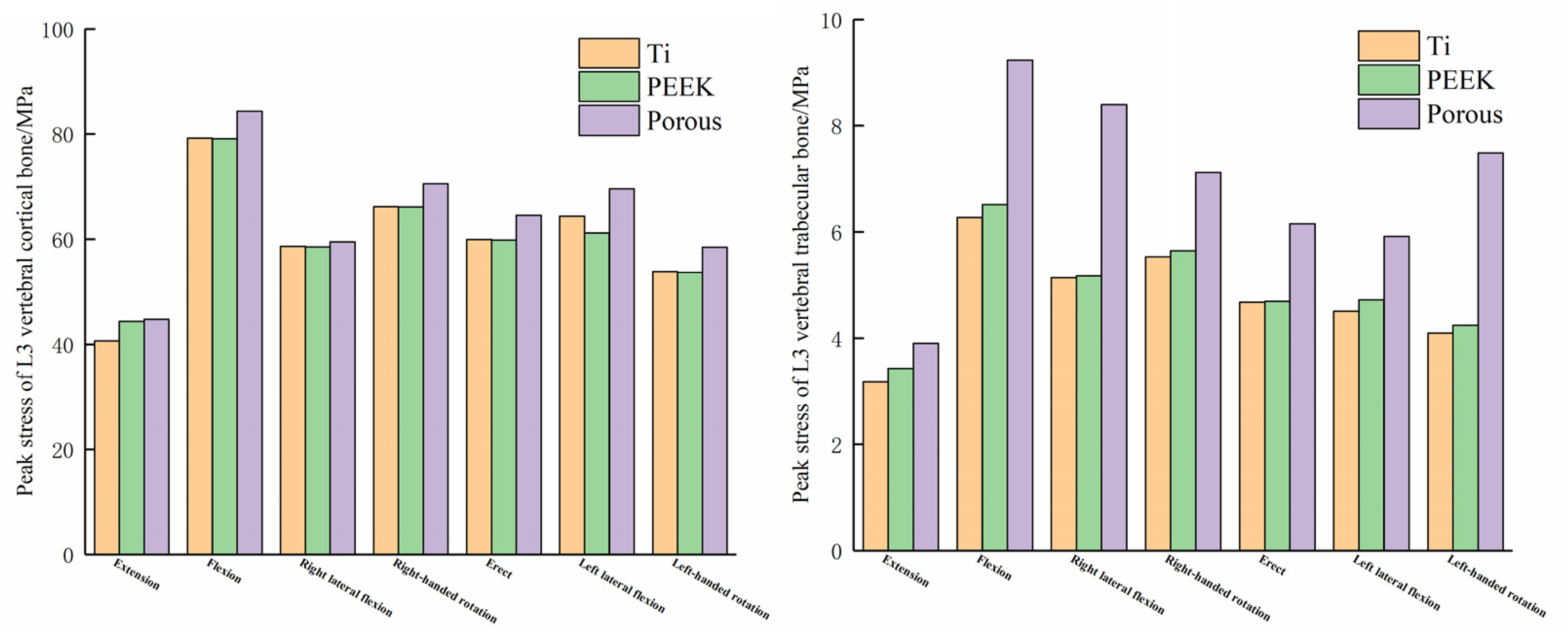
Peak stress of L3 vertebral body, (a) Peak stress of L3 vertebral cortical bone, (b) Peak stress of L3 vertebral trabecular bone.
The peak and increase of cortical bone stress in L3 vertebrae under three different fusion cages.
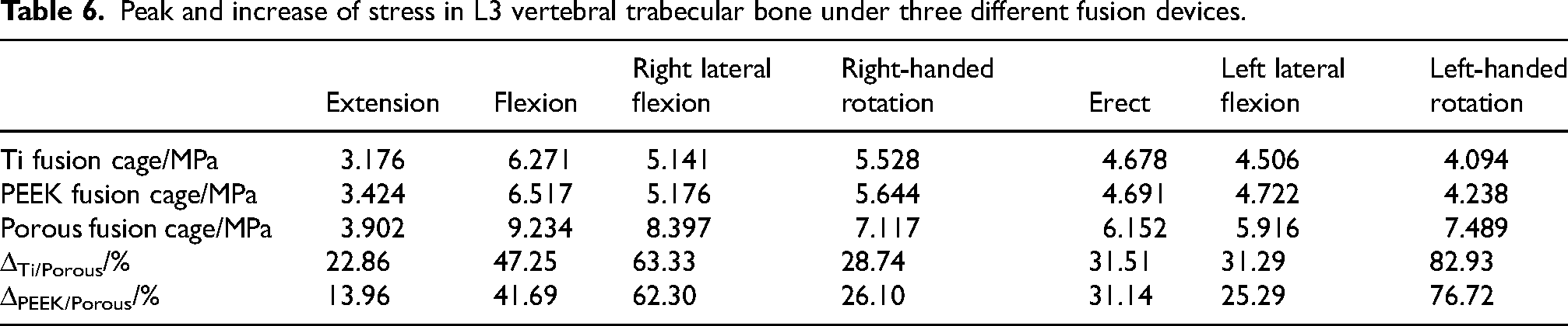
In a similar manner, the maximum peak stress in the cancellous bone of the L3 vertebra occurred during flexion condition at 9.234 MPa, and the minimum value occurred during extension at 3.176 MPa regardless of the interbody fusion cage type implanted. The peak stress in the L3 cancellous bone after implantation of the porous fusion cage was greater than that implanted in the Ti and PEEK fusion cages under all seven working conditions. Compared with each other, the peak stress in the cancellous bone under the PEEK fusion cage was slightly higher than that under the Ti fusion cage. The specific increases are shown in Table 6. Implantation of the porous interbody fusion cage resulted in an 82.93% and 22.86% maximum and minimum increase in peak L3 cancellous bone stress relative to Ti interbody fusion cage, and a 76.72% and 13.96% maximum and minimum increase relative to PEEK interbody fusion cage, respectively.
Peak and increase of stress in L3 vertebral trabecular bone under three different fusion devices.
Discussion
This study, employed a combined micro-macro multiscale approach to perform the topology optimisation of personalised interbody fusion cage and the osteotomy correction surgery carried out. The postoperative lumbar spine finite element models of the implanted optimised porous fusion cage, the Ti fusion cage, and PEEK fusion cage were established respectively. The findings revealed that under seven working conditions – extension, flexion, right lateral bending, right rotation, erect, left lateral bending, and left rotation – the Porous interbody fusion cage had superior mechanical properties compared with Ti and PEEK fusion cages. With such properties, the porous cages have the potential to reduce the risk of stress shielding and subsidence.
The volume of the porous intervertebral fusion cage obtained after multi-scale topology optimisation was 2587.80 mm3, while the volume of the Ti and PEEK intervertebral fusion cage was 5456.32 mm3. This represents a volume reduction of 52.57%, which greatly reduces the mass of the fusion cage, achieves a lighter design, and reduces the pressure of the fusion cage on the upper and lower vertebrae. It also significantly decreases the contact area between the fusion device and the vertebrae, which helps to fill the bone implant, promote transfer of nutrients as well as the transfer and growth of bone cells. 39
The peak stresses in the porous interbody fusion cage were far greater than those in the Ti and PEEK interbody fusion cages under all seven working conditions, with maximum increases of 242.76% and 252.46%, respectively, and minimum increases of 17.60% and 156.06%, respectively. The stresses were concentrated in the inner wall of the porous structure. Under normal physiological loading, regions of the high stress concentration within the porous interbody fusion cage are at risk of local collapse. 40 In order to mitigate the problems of stress peaks and localised stress concentrations, it is recommended that frame structures be constructed over the porous interbody fusion cage.
Stress shielding is a major problem facing intervertebral fusion cage.41,42 The porous structure of the optimised fusion cage had a modulus of elasticity of 25470 MPa, which is 76.85% lower than that of the original Ti material, which helps to reduce the occurrence of stress shielding phenomenon. Meanwhile, the fusion cage stiffness, one of the indicators for evaluating the stress shielding problems, and the peak strain values of the porous intervertebral fusion cage were improved by 131.40%-686.51% compared with the original Ti fusion cage under seven working conditions. These results shows that the porous intervertebral fusion cage has a significant reduction in stiffness compared to the initial Ti fusion cage, which further helps to reduce stress-shielding effect.
The peak stress in the bone is also one of the indicators of stress shielding of the bone by the fusion cage. The peak stresses in the L3 cortical bone post-implantation of the porous fusion cage were greater than those post-implantation of the Ti and PEEK cages under all seven working conditions. Compared with Ti interbody fusion cage, the optimised porous fusion cage increased the peak L3 cortical bone stress by 10.58%, 6.35%, 1.49%, 6.63%, 7.56%, 13.36%, and 8.69%, respectively, and compared with PEEK interbody fusion cage, the optimised porous fusion cage increased the peak L3 cortical bone stress by 0.99%, 6.54%, and 1.69%, respectively, 6.73%, 7.74%, 13.52%, and 8.98%, respectively. This suggests that compared to Ti and PEEK interbody fusion cages, the porous interbody fusion cages have the ability to further increase cortical bone stress and promote cortical bone growth, while reducing the occurrence of stress shielding phenomenon.
In a similar manner, the peak stress in the L3 cancellous bone after implantation of the porous interbody fusion cage was also greater than that of the implanted Ti and PEEK interbody fusion cages in all working conditions. The porous interbody fusion cage was found to increase the peak cancellous bone stress by 22.86% to 82.93% compared to the Ti fusion cage, and by 13.96% to 76.72% compared with PEEK fusion cage. Al these mean that the porous interbody fusion cage improves cancellous bone stress, reduces stress shielding, promotes bone tissue growth and remodelling of the cancellous bone.
From a clinical point of view, medical implants such as intervertebral fusion cages cannot be removed after the vertebral bone has grown completely, which means that they are should be biocompatible and securely attached to the bone. In the case of Ti interbody fusion cages, for example, 90% of them need to be refurbished postoperatively, for which 80% of these, are due to loosening of the fusion to vertebral bone. 43 In contrast, porous intervertebral fusion cage is designed to facilitate better integration with bone grafts due to the extensive pore structures in topology optimisation at macro- and micro-levels. 16 Personalised fusion cage are usually produced using 3D printing. Porous intervertebral fusion cages 3D printed using Ti were found to exhibit excellent biocompatibility, as verified by experiments on corrosion resistance and bone implantation. 44 Porous interbody fusion cages are thus better suited for long term retention as they fused more easily to the bone compared with conventional interbody fusion cage.
There are however some limitations in this study. The lumbar spine model did not account for the influence of muscles and the spinal cord. The post-osteotomy lumbar spine model is asymmetric, while the design of personalised interbody fusion cage has a symmetric structure which may contribute to increased concentration of stress. Furthermore, the foramen in the porous interbody fusion cage were replaced by a solid that was endowed with the material properties of the porous structure, which may have an impact on the stress distribution of the cage. further research will address these issues, and plans have been made to embark on them.
Conclusion
The following conclusions can be drawn: ① The optimised porous intervertebral fusion cage has a significantly reduced volume compared with the initial fusion cage, achieving a lighter design which reduces pressure on the vertebral bone; the optimised porous fusion cage reduces the surface area in contact with the vertebral bone, which is better suited to the filling of the bone implant, facilitating the exchange of nutrients as well as the transfer and growth of osteoblasts. Areas of high stress concentration in the porous interbody fusion cage are at risk of local collapse, and a frame structure should be constructed to reduce stress concentrations and spikes. ② The elastic modulus of the pore structure of the optimised porous intervertebral fusion cage decreased significantly, resulting in a dramatic increase in the peak strain of the fusion cage compared with the pre-optimised one. The significant decrease in the stiffness of the porous intervertebral fusion cage could greatly improve the stress shielding effect. ③ The porous interbody fusion cage can significantly increase cortical bone stress, which can promote more growth of the cortical bone, while reducing the appearance of stress shielding phenomenon. ④ The porous interbody fusion cage is also capable of increasing cancellous bone stress, which may promote bone tissue growth and remodelling while reducing stress shielding. ⑤ From a clinical point of view, the porous interbody fusion cage has good biocompatibility and prevents loosening and dislocation, making it more suitable for postoperative conditions and improving the likelihood of successful fusion.
Footnotes
Acknowledgments
The authors have no acknowledgments.
Funding
The authors disclosed receipt of the following financial support for the research, authorship, and/or publication of this article: The National Natural Science Foundation of China (No. 32260235).
Declaration of conflicting interests
The authors declared no potential conflicts of interest with respect to the research, authorship, and/or publication of this article.