
Abstract
According to US National Oceanic and Atmospheric Administration (NOAA), we have only explored five percent of our world ocean. Among the ocean exploration tasks, underwater object detection is a multidisciplinary challenge that extends beyond engineering into fields such as oceanography, marine biology, and environmental science. Scientifically, it involves understanding the complex interactions between sound waves, light, and water, as well as the navigation dynamics within marine environments. The underwater environment presents unique physical challenges for object detection due to factors like light attenuation, turbidity, and the variability of acoustic propagation. This paper introduces a cost-effective autonomous underwater prototype for real-time detection, and localization of small underwater objects (e.g., archaeological artifacts, parts of infrastructures, wreckage debris, but also life forms like fishes, corals etc.) in shallow waters. The system combines object identification with autonomous navigation capabilities. It consists of an autonomous underwater vehicle equipped with sensors, cameras, and localization tools, as well as a ground control station for monitoring and intervention. In particular, we focus on a case study about detecting and reporting the locations of unexploded ordnance materials, contributing to the monitoring of underwater hazards in conflict-affected regions. Key contributions include the integration of a cost-effective autonomous remotely operated vehicle with sensors and software for real-time detection and localization of small underwater objects, as well as an annotated dataset of UXO images, usable as a benchmark.
Keywords
Introduction
In this paper, we present an autonomous evolution of a previous system (Foresti and Scagnetto 1 ), designed for the detection and localization of small underwater objects, with a specific focus on unexploded ordnance (UXO). Despite being still cost-effective, the new system features both object detection and autonomous navigation capabilities (the previous version, instead, must be manually piloted). It consists of an unmanned underwater vehicle (UUV) equipped with sensors, cameras, and localization tools, and a Ground Control Station (GCS) to oversee the autonomous tasks and intervene when needed. The GCS also handles vision processing tasks and manages the decision-making algorithms that control the remotely operated vehicle (ROV). From a software perspective, the system includes: (i) the UUV’s operating system and automation scripts, which govern autonomous navigation, (ii) the GCS application, which provides an interface for the operator and stores to disk the received images, and (iii) the software which filters, enhances, and applies detection algorithms on the acquired images. Further details are provided in Section 3.
Seabeds, riverbeds, and lakebeds are often scattered with small underwater objects. In particular, we address the challenge of detecting and localizing UXO, i.e., ordnance and explosive waste (OEW), which represents a significant safety risk, especially in countries affected by past or recent conflicts. Natural events, like storms, may cause coastal erosion or drifting debris which in turn can occasionally uncover unexploded ordnance, either partially or fully, that was dropped by planes or fired by mortars. For example, ANSA
2
mentions the discovery of a World War II UXO on the coast near Rome. Furthermore, in 2017, the Italian Navy’s demining division worked to remove around 22,000 explosive objects from seas, lakes, and rivers, with more than 10,000 of these discovered in the first half of 2019 alone. According to the U.S. “Government’s Strategic Environmental Research and Development Programme (SERDP)”, over 40,000 Km
Apart from the immediate danger posed by undetonated items, there are the risks of the underwater ecosystem exposure to the chemical compounds which may leak from the shells. As these devices corrode and rust over time, they eventually break open and release toxic substances into the environment. Thus, the development of an autonomous system capable of detecting and monitoring unexploded ordnance in underwater scenarios can contribute to both public safety and environmental protection.
The main innovative aspects of the paper are as follows:
a cost-effective autonomous underwater ROV capable of patrolling an underwater area, detecting in real-time the presence of small underwater objects (e.g., UXO), and transmitting the object’s Global Navigation Satellite System (GNSS) coordinates to the GCS; an annotated dataset of UXO images, enhancing the training data for object detection algorithms, with a particular focus on distortion techniques to improve detection in murky/turbid water conditions.
As anticipated, while the tests have been conducted using UXOs, the system is designed to be applicable to a broader range of underwater objects, providing a versatile tool for underwater object detection in various contexts. It is sufficient to switch the given classifier with another one (e.g., an amphorae detection network for submerged archaeological sites corresponding to ancient Roman ships wreckages).
An important remark is to establish what “small object” means in this paper. Differently from Chen and MJ,
4
we do not use the definition taken from the MS COCO dataset.
5
1
Indeed, since the ROV can move freely, it can get very close to objects of interest; whence, their dimensions can be rather large w.r.t. the MS COCO dataset definition. Instead, we focus on physical dimensions of objects, taking as a small object something which can fit completely in the field of view of a nearby camera. Underwater, especially in murky waters, visibility is severely limited by haziness, backscattering etc.; hence, the ROV must get very close to the objects in order to frame them with the camera: this fact limits the dimensions of suitable objects which can enter the field of view without occlusions, distortions or croppings. According to our experience, we are speaking of objects which can fit in less than 1 m
Synopsis
The outline of the remaining sections is structured as follows: related work is discussed in Section 2. The proposed system is introduced in Section 3, with the hardware and software architectures described, respectively, in Section 3.1 and in Section 3.2. Section 4 is devoted to the annotated dataset, while experimental tests are documented in Section 5. Finally, conclusions and directions for future work appear in Section 6.
Related work
This section briefly surveys the state-of-the-art of the two main areas addressed by the work, namely, object detection and autonomous navigation in underwater environments.
Underwater object detection
The research topics of computer vision and object detection have an advanced state-of-art, accounted for by many scientific papers, and applied in several scenarios. Indeed, considering only recent works, applications go from landslide prediction in Guerrero-Rodriguez et al., 6 to identification of overweight vehicles in Li et al., 7 and real-time structural vibration measurement in Pan et al. 8 Another recent study in Jiang et al. 9 proposes a CNN-based system for fast rivet identification and defect diagnosis in steel bridges, classifying rivets as normal, rusted, loose, or missing. A multi-scale moving window technique improves small rivet detection, while a continuous dataset enrichment strategy enhances training efficiency. Tested on a historical bridge in Gjerstad, the system achieves a 96.3% rivet identification rate, with high classification accuracy and robustness. Conditions affecting detection performance are also analyzed.
Recently, many works have focused on improving well known models, in order to address real-time scenarios. For instance, in Jiang et al., 10 the authors propose YOLOMF, an efficient lightweight model for multi-damage recognition in concrete bridges, improving YOLOv4 with MobileNetv3 and fused inverted residual blocks. YOLOMF achieves 85 fps, demonstrating high accuracy and real-time damage detection capability in complex environments.
Another example is the development of 3D object detection solutions, going beyond classic “flat” 2D detections. For instance, in Shen et al. 11 the authors address challenges in 3D object detection for construction scene analysis tasks, including limited datasets, depth estimation difficulties, and the absence of 3D cues from single RGB images. In particular, they propose an improved cascade-based network with a transformer backbone and boundary-patch-refinement to enhance hierarchical feature learning and object boundary accuracy. Moreover, a self-supervised monocular depth learning method improves depth estimation from construction site videos with unknown camera parameters. Finally, a pseudo-LiDAR approach and a density-based clustering algorithm enable 3D object detection without 3D labels.
Research about autonomous driving in urban scenarios pushed further the limits, developing multi-object tracking (MOT)systems in crowded urban environments. For instance, in Urdiales et al., 12 a 3D MOT system is presented, integrating a Kalman filter with deep learning. In particular, three neural networks (a convolutional LSTM for spatiotemporal feature extraction, a Siamese network for track-detection similarity measurement, and a recurrent LSTM for 3D and bounding box refinement) are trained on track sequences, enhancing tracking-by-detection, reducing identity switches, and handling missed observations.
Moreover, besides RGB cameras, other kinds of sensors are often used for object detection. For instance, in Chaverot et al., 13 the authors investigate preprocessing techniques to enhance object detection in thermal images, which typically suffer from low contrast, blurriness, and low resolution. Mathematical morphology, implemented using the Logarithmic Image Processing (LIP) framework, is applied to improve small bright object detection, while deblurring and super-resolution methods enhance overall image quality. The effectiveness of these approaches is evaluated on the FLIR dataset, showing significant improvements in detection performance using CNN-based models like YOLOv4 and EfficientDet.
However, the detection of objects and, in particular, of unexploded ordnance, particularly in shallow waters, is an ongoing challenge, due to the difficulties posed by the underwater scenario. Various systems and techniques have been developed to address those issues. In the following, we group them according to the main sensor type used for the detection.
Early Systems
The work presented in Summey et al., 14 was a pioneering system, combining sonar, laser scanning, and a gradiometer for surveying underwater ordnance, with advanced processing techniques to improve detection in cluttered environments.
Sonar Solutions
Later, sonar systems, (see, e.g., Brown et al. 15 ) employed 3D synthetic aperture sonar (SAS) for detecting buried objects, while other researchers (funded by the USA’s SERDP and Naval Research Office) explored the possibility of detecting and classifying UXO by acoustic analysis, using relevance vector machines (RVMs).16–19 Indeed, sonar-based systems are still dominant, due to their ability to detect buried objects and to operate in murky conditions. The authors of Beaujean et al. 20 utilized mosaicking for large-area scans followed by targeted re-acquisition in suspicious zones. The advent of machine learning allowed researchers to explore techniques such as active learning algorithms, 21 and methods for distinguishing different UXO materials based on sonar backscatter. 22 Visual analysis of sonar images, including forward-looking sonar and real-time detection techniques,23–25 has advanced, with approaches like non-linear CNNs achieving 99% accuracy in distinguishing UXOs from clutter. 26
Optical Sensor Systems
For direct optical observations, high-resolution images outperform sonars in target localization and identification, 20 but face challenges from underwater haze and limited visibility. Techniques such as image enhancement, colour correction, and deep learning models can help to overcome these problems.27–31 Several solutions are focused on the detection of fishes, using statistical estimation techniques, 32 or deep networks.33–35 Recently, few-shot learning approaches have been investigated for automatic object classification.36–38 An integrated system for underwater object detection is presented in Foresti and Scagnetto, 1 leveraging on an Alexnet CNN and low-cost hardware. Recently, the authors of Chen and MJ 4 presented a dynamic YOLO detector of small objects (in the sense of the MS COCO dataset 5 ) in underwater environments. A closely related work is presented in Jiao et al., 39 where a real-time underwater vision system, based on YOLOv5, is presented for damage classification and localization in underwater concrete infrastructures.
Generally, all the above mentioned approaches are tuned against a peculiar sensor type. Hence, by changing the sensor, the trained model risks suffering a loss of performance or no longer being able to detect anything. To avoid this issue, in Mohan and Simske, 40 a system supporting multiple imaging sensors is presented. In particular, a CNN architecture is designed in order to test cross-sensor object detection resiliency of maritime vessels in aerial images.
Autonomous underwater navigation
Autonomous navigation is a broad research topic covering a large variety of vehicles and application scenarios. For instance, in Grosset et al. 41 and Grosset et al. 42 the focus is on designing and implementing obstacle and collision avoidance, and task allocation between autonomous industrial vehicles in an Industry 4.0 setting. The authors provide a model and an agent-based simulation platform for testing their algorithms. As another example, in Jeon et al. 43 a 3D-LiDAR and optical camera system is used to implement an autonomous inspection solution of overhead transmission towers.
Overall, autonomous navigation in underwater scenarios represents a much more complex technical challenge due to the unstructured environment, the absence of GNSS signals, and sensor limitations. 44 This field has garnered increasing interest due to its applications in scientific, commercial, and military domains. In recent years, numerous approaches have been developed to address issues related to UUV localization and motion planning.
Underwater navigation is traditionally divided into three main approaches, as described in Zhang etal.
45
:
Integrated navigation combines these methods to improve robustness and accuracy. Recent reviews emphasize advancements in integrating SLAM (Simultaneous Localization and Mapping) with inertial sensors for enhanced localization accuracy. A good example is described in Xanthidis et al., 46 where the potential of autonomous navigation in complex environments is demonstrated by combining perception and planning to avoid obstacles and minimize path length. However, this approach does not address the active observation of visual points of interest, which is critical for monitoring missions.
Underwater environments present unique challenges, such as poor illumination, turbidity, and a lack of distinctive visual features. These conditions hinder state estimation based on visual data. In Xu et al., 47 the characteristics of an effective underwater image detector are outlined, emphasizing the ability to distinguish the target even in scenes with blurred, hazy, or non-standard colours.
Autonomous underwater navigation, where the UUV and the GCS share information to enhance localization, represents another promising approach. While this method has demonstrated potential for improving navigation accuracy, it requires reliable communication and advanced computational capabilities. Recent studies highlight the increasing focus on autonomous underwater systems and their potential to tackle the limitations of traditional navigation methods. 48
The proposed system
In the following, we introduce an evolution of the system presented in Foresti and Scagnetto. 1 Capitalizing on the latter, the focus is placed on increasing detection accuracy through advanced algorithms for better object identification and reduced false positives. The most significant improvement, however, is the addition of autonomous navigation capabilities, enabling the system to operate independently without the need for external intervention.
Although the system is designed to operate fully autonomously, it allows for manual intervention when needed, offering flexibility for the user. It complements traditional solutions like magnetometers or sonars, and can integrate additional sensors to enhance its capabilities. For instance, a support boat may carry out a preliminary exploration of a large area with a sonar/magnetometer, recording the position of suspicious areas, where potential objects are detected. Then, the ROV may be deployed to analyze in depth those zones, getting closer to the masses revealed by the sonar/magnetometer.
Indeed, the ROV’s compact design enables it to perform autonomous navigation in complex underwater environments, such as tunnels, ravines, or debris-filled areas that are unsafe for divers or bigger ROVs. This small size allows it to approach closely the objects of interest, minimizing image distortions and haze typically seen with larger systems.
On the software side, the system is highly parametric, allowing for easy customization of preprocessing algorithms and classifiers to meet specific mission needs.
The physical architecture
The components of the system are depicted in Figure 1: they comprise a Class II ROV (Remotely Operated Vehicle), based on the BlueROV2 platform developed by Blue Robotics, 49 the GCS 2 , and supporting components.
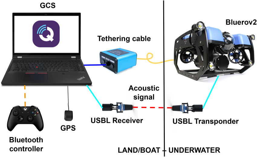
Wiring and connections of the system.
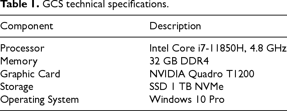
Key technical specifications of the GCS-laptop are summarized in Table 1.
GCS technical specifications.
The BlueROV2 is a compact ROV designed for underwater exploration and research, equipped with 8 thrusters (4 vertical, 4 horizontal), enabling a 6-DoF (Degrees of Freedom) control system along the yaw, roll and pitch axes. It features a depth sensor, temperature sensor, and an Inertial Measurement Unit (IMU) for precise navigation and stability, with a durable frame of anodized aluminum and sturd plastic. Key specifications are reported in Table 2.
BlueROV2 technical specifications.

The GCS connects to the ROV via a tether cable and an FXTI interface, enabling both devices to operate on the same network with assigned IPs (

Physical architecture of the proposed system.
The BlueROV2 features a 1080p HD camera capable of 60 FPS video recording, mounted on a tiltable mechanism for improved navigation and environmental observation. The camera connects directly to the Raspberry Pi, simplifying system architecture and enhancing reliability.
The ROV’s hybrid localization system combines GNSS and USBL technologies for accurate positioning. The GNSS receiver provides the GCS’s surface position, while the USBL system estimates the ROV’s 3D underwater location based on the acoustic signal response between the transceiver connected to the GCS (lowered into the water) and the transponder on board the ROV. This setup ensures robust tracking in the underwater environment (where GNSS signals cannot propagate), enabling precise navigation for tasks like inspections and environmental monitoring.
The logical architecture of the system is designed to tackle challenges specific to underwater environments, such as GNSS unavailability, limited visibility, and the need for real-time decision-making. QGroundControl, a versatile, MAVLink-based application, provides a user-friendly UDP interface for seamless communication with the ROV Figure 3.

Logical architecture of the proposed system.
On board the drone, a script acquires real-time data and streams video via UDP to the GCS. This video feed is critical for navigation and detecting objects like UXOs, obstacles, or points of interest; when the visibility is low or water turbidity is high a sonar is also used to avoid collisions and moving safely the ROV.
At the GCS, two scripts ensure the system’s functionality: one handles autonomous navigation via the MAVLink protocol (allowing the automation of tasks such as waypoint navigation, obstacle avoidance, and environmental monitoring, without requiring constant manual intervention), while the other processes the video stream received from the ROV, using YOLOv5 for object detection. The navigation script uses GNSS coordinates to guide the drone when signals are available, switching to joystick override and onboard sensors when GNSS is unreliable. The object detection script leverages YOLOv5 to identify obstacles or other relevant underwater objects, trained on a dataset designed to handle conditions like noise, murkiness, and varying light.
The navigation script is built on MAVLink, a lightweight and versatile protocol enabling autonomous operations. It manages navigation in two modes:
GNSS-based navigation using onboard GNSS when the ROV is on the surface; USBL-based localization when underwater.
When GNSS is available, the script calculates the drone’s position relative to the target and guides it along a straight path while continuously monitoring accuracy. In GNSS-denied environments, the script overrides joystick controls to modify motor roll, pitch, and thrust directly, enabling movement in the X, Y, and Z axes. This ensures seamless navigation using only onboard sensors and the compass for orientation.
Two autonomous patrolling methods have been implemented to address different mission requirements (Figure 4):
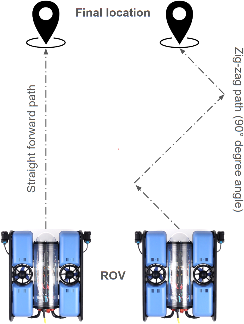
Autonomous patrolling methods.

Tank walls detection by sonar. The ROV is moving with the onboard sonar (a), producing the acoustic image with the nearby tank walls (b), which is converted in B/W (c); then the noise is removed from the centre of the image (d). The result may then be used to successfully apply the Hough transform (e).
The script’s modular design supports extensions like obstacle avoidance or dynamic path planning, showcasing the adaptability of MAVLink for underwater environments. For instance, in Figure 5 we can see how the onboard sonar (a) can be used to detect the walls of the tank we used during the tests, applying the well-known Hough transform (Duda and Hart
51
). First of all the acoustic image (b) is converted in B/W format (c); then the noise is removed from the centre of the image (d). The result may then be used to successfully apply the Hough transform (e). Indeed, the latter allows one to infer the equation of lines in the cartesian plane with origin in the ROV Sonar. For instance, in Figure 6, the red line represents a wall against which the ROV is going to collide with an angle of
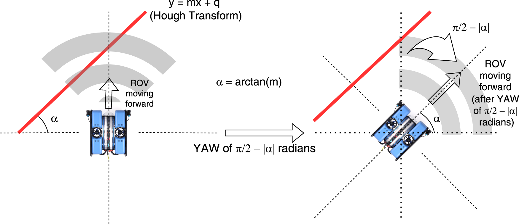
Wall detection and route correction procedure: the red line represents the wall detected by the Hough transform algorithm; a yaw of
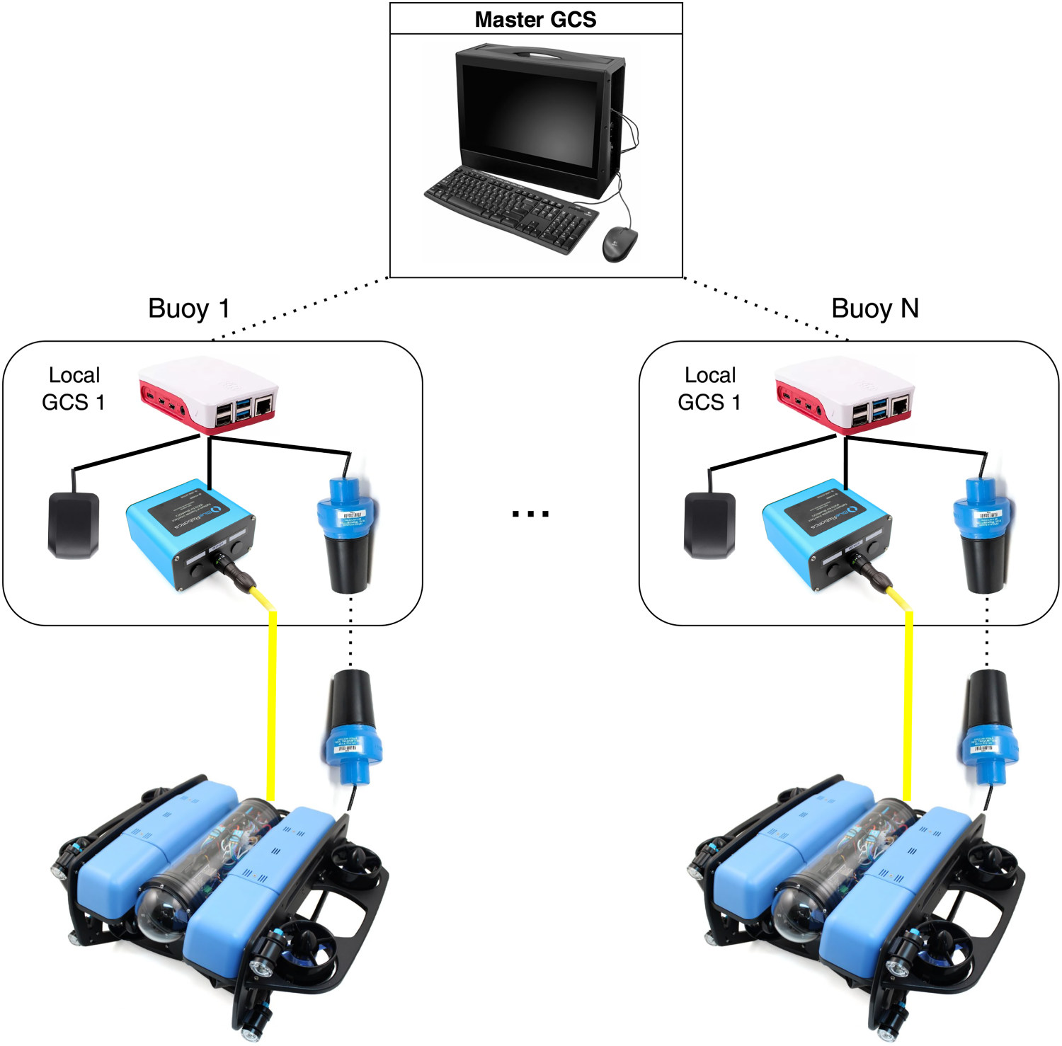
Architecture for a set of ROVs, with local GCSs and a common master GCS.
The object detection system uses YOLOv5 (specifically the yolov5s variant, 52 ), a deep learning model optimized for real-time performance. The training of the network was carried out on a curated dataset of 12,000 labelled images, with 80% used for training and 20% for validation. Extensive preprocessing, including data augmentation and noise simulation, ensures the model’s robustness under challenging underwater conditions. After 100 training epochs, the model achieved over 95% validation accuracy.
It is worth to notice that, as far as computational resources are concerned, the proposed logical architecture scales well with the number of deployable ROVs, for the control part (i.e., the automated mission logic). The only crucial point is handling in real-time the object detection in the video streaming towards the GCS. The small model of YOLOv5 ensures that an image can be processed in 6.4 ms using a GPU. Hence, for either a single ROV or a small number of vehicles, a laptop with a decent GPU is enough powerful to play the role of GCS. Otherwise, in more complicated scenarios, one can adopt the scheme depicted in Figure 7, embedding the control part in small computers (e.g., Raspberry Pi 4 devices), which become the local GCSs for the single ROVs. Thus, they can be deployed encased in buoys. The latter can then communicate via Wi-Fi to a powerful master GCS, receiving all the video streams and performing object detection. Once an object is detected in a frame, the corresponding local GCS is informed, taking a decision about further movements or actions of the associated ROV.
Please notice that, with the possibility of replacing the Raspberry Pis onboard the buoys with more powerful embedded computers (e.g., some Nvidia Jetson Orin Nano devices), an alternative approach is possible. Indeed, in that case one could carry out also the object detection process locally, reducing the master GCS to a central coordination node, with much lower hardware requirements (e.g., no GPU).
Validation tests included controlled experiments with GoPro-recorded videos and real-world trials with the BlueROV2. These evaluations confirmed the model’s ability to reliably detect objects in dynamic underwater environments.
We conclude this section observing that the described system can be deployed and used in real outdoor scenarios, including sea, lakes and rivers. The latter, of course, are the most challenging environments, due to possible strong currents. However, the eight T200 motors of the BlueROV2 are powerful enough to navigate without being dragged away: reaching 3 knots of speed, they are able to contrast currents of 1-1.5 knots, which is far enough for the ROV to navigate near the shoreline of the rivers of our region. In case of stronger currents they can be substituted by the T500 version provided by BlueRobotics (with a threefold thrust).
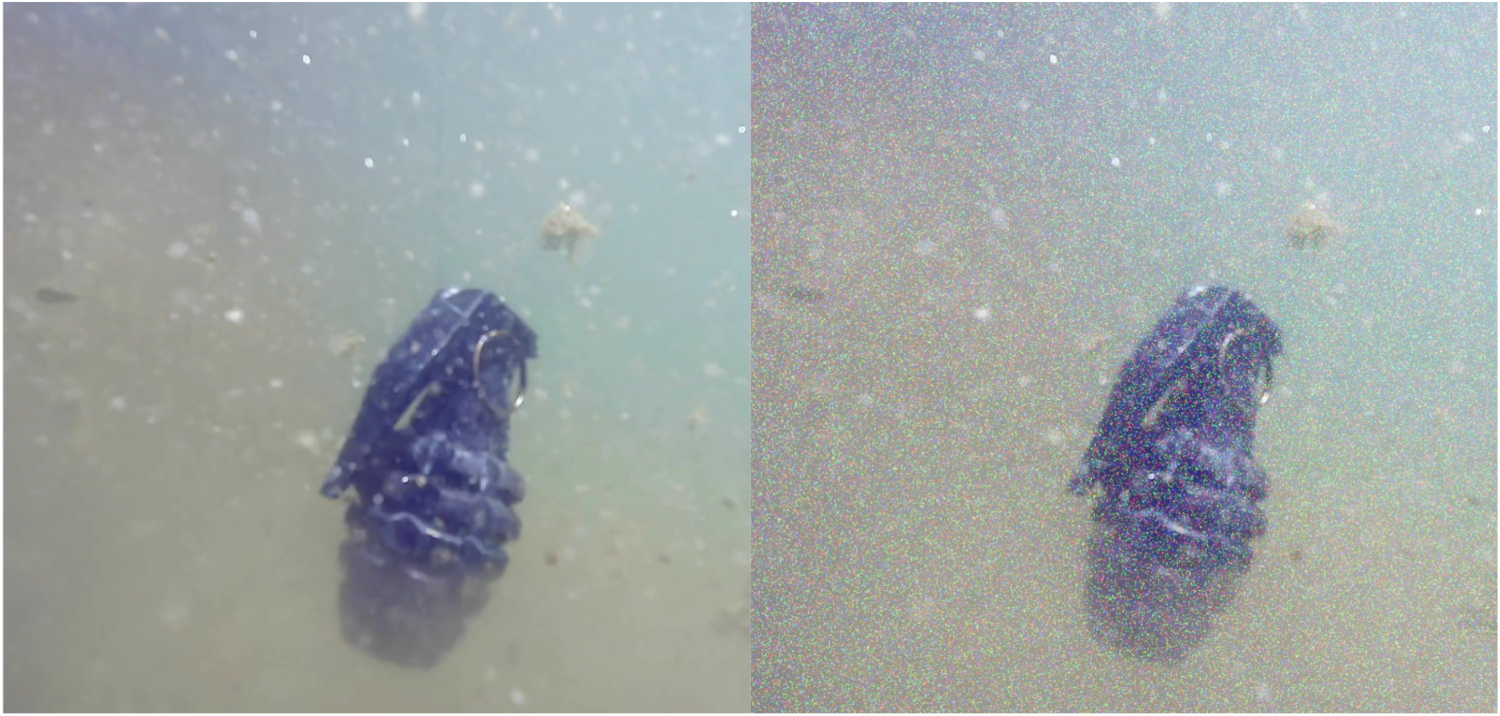
An example image from the in-house acquisition before (left) and after (right) the application of gaussian blur.
The initial dataset was derived from Foresti and Scagnetto, 53 and it consisted of 3,378 images of UXOs, which were gathered using a Python-based web crawler. Subsequently, after selecting a subset of 2,833 images, these were meticulously annotated with object labels and boxes through the VGG Image Annotator v.2.0.11 (VIA), 54 a tool for image labelling in machine learning tasks.
Recognizing that a larger and more diverse dataset would be crucial for improving the robustness and generalization ability of our model, we augmented and expanded it. Indeed, we added new frames directly from test videos captured using the BlueROV2, significantly increasing the size of the dataset while also introducing valuable diversity in the images (providing different angles, partial object views, and a variety of perspectives).

A test conducted in a murky environment: The ROV does an autonomous path in a murky pool and detects correctly an UXO.
Furthermore, we applied several data augmentation techniques. The techniques we used included geometric transformations such as rotations and flips, enforcing the model to detect objects from various orientations, and improving its ability to handle different object alignments and viewpoints. Additionally, we applied colour-based transformations, including adjustments to brightness levels, simulating the challenging visual conditions often encountered in underwater environments. Indeed, underwater imagery is frequently characterized by varying light conditions, murkiness, and distortion due to water particles, which can make object detection more difficult.
Another important augmentation step involved the introduction of Gaussian noise into the images (see, e.g., Figure 8). This noise, akin to the visual disruptions caused by water turbulence or sensor limitations in underwater systems, further enriched the diversity of the dataset, ensuring that the model is trained to detect objects in less predictable, noisy conditions.
To perform these augmentations efficiently, we employed Albumentations (v. 2.0.2), 55 a Python library widely recognized for its speed and flexibility in implementing complex image transformations. As to the noise, it was introduced using NumPy by applying Gaussian noise to the dataset.
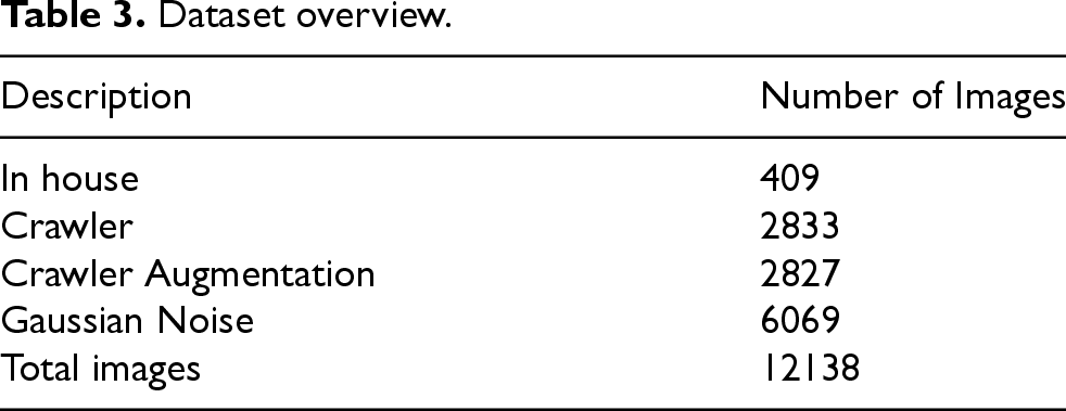
Specifically, we applied data augmentation to the images obtained from the web crawler. In fact, the number of images is effectively doubled by randomly applying transformations to each image, including rotations, flips, and changes in brightness, which can also be combined. Subsequently, images acquired in-house were included in the testing phases, and Gaussian noise was applied to the entire dataset, further doubling the dataset generated from the augmentation process. Thus, our final dataset grew to 12,138 images Table 3.
This enriched dataset was then partitioned into two subsets: the first for training and the second for validation purposes. The first was used to train the network, while the latter was reserved for evaluating its performance during the training process. We ensured that both sets were well-balanced and representative of the overall dataset, helping to avoid overfitting and ensuring that the model would generalize well to unseen data.
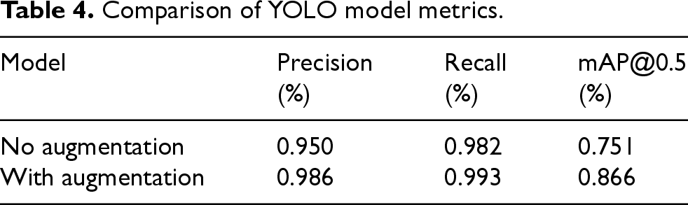
Table 4 shows that:
as far as precision is concerned, the improvement with data augmentation is relatively modest (from 95.0% to 98.6%)
3
; instead, there is a significant increase in mAP@0.5, rising from 75.1% to 86.6%: this highlights the effectiveness of augmentation in improving the model’s overall efficiency and its skill to detect objects more accurately; the recall also shows a slight improvement, confirming better generalization.
Dataset overview.
Comparison of YOLO model metrics.
The experimental tests for the underwater autonomous ROV system were carried out in three distinct stages: laboratory tests, pool tests, and outdoor tests in a murky, muddy tank. Each of these stages focused on different aspects of the system, from object detection to autonomous navigation.
The first set of tests was conducted in the laboratory, where the primary objective was to evaluate the object detection capabilities of the ROV. During these tests, the ROV was placed in a controlled environment, and an UXO like object was positioned in front of the ROV. The detection script was activated, and the system was able to recognize the target, confirming its detection along with an indication of detection precision. These dry tests helped validate that the object detection algorithm, specifically the custom YOLOv5 model, was functioning correctly under ideal conditions without the complexities of environmental variables like water turbidity or motion blur.
Tests were also conducted in varying lighting conditions, including both daylight and cloudy conditions, with the pool containing murky water and particulate matter, simulating real-world underwater environments Figure 9.
Next, the ROV was tested in a controlled pool environment. These tests served as the next step in evaluating the system’s performance in real-world conditions. The ROV was manually operated by an operator, with the target object placed both on the pool’s floor and at mid-water height. The same detection script from the dry tests was used to ensure that the object was detected accurately, regardless of whether it was on the floor or suspended in the water. Additionally, in this pool setup, the autonomous navigation script was also tested. The ROV navigated using two modes: point-to-point navigation, where the ROV autonomously navigated between specific coordinates, and by overriding the joystick controls from the script, without using GNSS data. These tests were crucial in assessing the ROV ability to navigate autonomously and handle dynamic conditions while maintaining the detection process.
Finally, the most challenging tests were conducted in an outdoor tank filled with very dirty and murky water, simulating highly challenging real-world conditions. The ROV performed several autonomous patrols in the tank, with two different navigation patterns: a straight-line patrol (moving only forward) and a zigzag pattern, designed to cover a larger area. During these patrols, the ROV would stop and transmit the coordinates of any detected object. This stage tested the full integration of the detection and navigation systems, as the ROV was required to autonomously navigate while continuously scanning for objects, stopping when a target was detected, and then transmitting the location data. These tests helped evaluating how the ROV systems performed under poor visibility conditions, as well as its ability to integrate detection with real-time navigation in a more unpredictable, real-world setting.
The choice of automatically stopping the ROV after an object detection has been made in order to simplify the tests carried out in this work. However, it is important to notice that the system architecture is open to the implementation of whatsoever action. For instance, at the URL referenced in Tavaris et al. 56 we provide a video illustrating the scenario where, after a successful detection of an UXO, the GCS receives the related coordinates, and commands an aerial drone to take off and move over the detection point (i.e., on the vertical of it). This is an example of an automatic coordination between underwater and aerial unmanned vehicles, and was the main topic of a recent project with the Italian Navy.
Table 5 highlights the strong performance of the detection models across all tested environments, with accuracy exceeding 96% in every case. The results in the clean pool environment show the highest accuracy (98.7%), demonstrating the model’s capability to perform exceptionally well under controlled conditions with clear water. However, in the outdoor environment, the accuracy is slightly lower at 98.1%. This drop is likely due to the challenging lighting conditions, particularly the reflections of sunlight on the water surface, which introduce visual artifacts and reduce the clarity of the images.
Accuracy of the models on frames acquired from videos recorded in different environments.

Accuracy of the models on frames acquired from videos recorded in different environments.
This result was anticipated, as the training dataset predominantly featured underwater scenes, making the model more specialized in handling such scenarios. The robustness of the model in adapting to these variations still confirms its reliability, but future improvements could involve diversifying the training dataset to include more examples of outdoor water environments to mitigate the impact of reflective noise.
For the sake of a more thorough assessment about the benefits and effectiveness of the enrichment process, we carried out the following extensive benchmark:
we prepared a tank filled with murky water and with a lot of mud and debris on the bottom; we submerged an ordnance replica attached to a fishing rod by means of a fishing line; we recorded a video of the ordnance replica in several different conditions (e.g., suspended in the water, on the bottom, partially covered by mud/debris, and sometimes dragged (i.e., in motion) by pulling the fishing rod; we used the video footage as input to the two models, namely, the initial one (trained on 2,833 images selected from Foresti and Scagnetto
1
) and the enriched one described in Section 4.
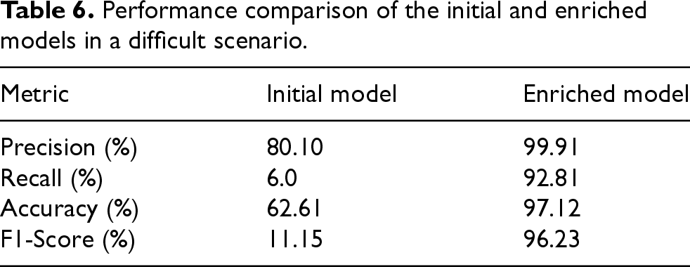
The length of the video footage amounted to 8m 10s, yielding 13,208 frames. In table 6 the results of the above mentioned test are reported, according to the usual metrics of precision, recall, accuracy and F1-measure. We can see that the enrichment process by means of the techniques described in this section has proven to be quite effective, raising all the scores in a considerable way (especially, in reducing false negatives). We still miss some detections, due to the difficulty of the scenario (partial/full occlusions of the ordnance replica with the mud/debris on the bottom, and lots of backscatter effects), but the performance is quite good. The detection video using the Enriched Model is available at.
56
Performance comparison of the initial and enriched models in a difficult scenario.
These experiments provided valuable insights into the performance and reliability of the system, demonstrating that the object detection and autonomous navigation functionalities were both robust and adaptable to varying environmental conditions, from controlled settings to challenging outdoor conditions.
Some videos of the experiments carried out both with in-house acquired footage (using the ROV), and with videos downloaded from the Web are available at the URL provided in Tavaris et al. 56
Of course, proposing a new dataset and a new trained model, one may wonder how the latter compares to the state-of-the-art, and, more specifically in this case, to solutions in the field of UXO detection by means of computer vision techniques. Unfortunately, there are not so many papers about visually detecting unexploded ordnance materials, especially in underwater scenarios. Considering our previous work (Foresti and Scagnetto 1 ), we now have several improvements: migrating from an AlexNet-based model to a YOLOv5s one, we have much faster UXO detections (with real-time boxes), and slightly better precision and recall (compare the second row of Table 5 with the first row of Table 6 in Foresti and Scagnetto 1 ). Another interesting related work is described in Colreavy-Donnelly et al., 57 where a CNN is used to detect “improvised explosive devices” (IEDs) in “rural or built-up urban environments”. They achieve an accuracy of 98.7%, in well-lit conditions, i.e., a score we attain only in the clean pool scenario (see Table 5), but a comparison with our system is unfair, since the input data of the CNN are harvested by an ad-hoc sensor which is composed by a ground penetrating radar, a thermal sensor, an infrared sensor, an ultraviolet sensor and a camera. Thus, they have a wealth of data, allowing one to detect also buried or strongly occluded IEDs. Considering the detection of other kinds of objects/entities, in Qin et al. 33 an annotated dataset of 22,370 images of 23 species of fishes is used as a benchmark for the proposed classification CNN, named, Deepfish. The latter shows the state-of-the-art accuracy of 98.64%. The solution proposed in this paper achieves an average accuracy of 97.8% (considering the three scenarios in Table 5), which is not bad, considering that our dataset is nearly equal in size to the number of images of the most populated category of Qin et al. 33
This paper introduces a cost-effective (overall costs are less than 15,000 USD) autonomous underwater system designed for real-time detection and localization of UXO in shallow waters, by means of advanced image processing and autonomous navigation.
Moreover, the building of an UXO images dataset, using underwater images acquired by the ROV and data augmentation, enhances object detection model robustness.
Experimental tests in diverse environments –laboratory, pool, and murky outdoor waters– validate the system’s object detection and autonomous navigation capabilities, minimizing risks and improving efficiency in UXO detection.
In conclusion, the system demonstrates significant potential in safeguarding coastal areas and protecting marine ecosystems, laying the groundwork for future advancements in UXO detection and underwater autonomy.
Future improvements will take into account the integration of onboard advanced telemetry systems (e.g., Scagnetto et al. 58 and Odetti et al. 59 ), covering many more sensors, in order to implement more refined navigation algorithms for complex underwater conditions. Moreover, datasets will be expanded for diverse environments, enabling situational real-time onboard decision-making, and integrating multisensor fusion (e.g., sonar, magnetometers) for enhanced accuracy in poor visibility. Indeed, applying data fusion techniques, especially between signals of audio and video sensors, turns out to be a fruitful approach in detecting objects (e.g., aerial drones 60 ) or events (emergency vehicles 61 ).
Alternatively, due to the lack of publicly available datasets, an interesting research direction could be represented by self-supervised learning approaches in the style of Rafiei et al. 62 and Rafiei et al. 63
Footnotes
Funding
The author(s) disclosed receipt of the following financial support for the research, authorship, and/or publication of this article: Support to this work was granted by the FSE 4 fund, by the “Interdepartmental Project on Artificial Intelligence” (2020-25) of the University of Udine, and by the “Proactive Counter-UAV” (2018-2023) [Contract nr. 2066 of 06/12/2019 – SMART CIG Z282908BDF] and “ARGOS” (2023-2025) [Contract nr. 20695 of 15/06/2023 – SMART CIG ZD7381D487] PNRM projects of the Italian Ministry of Defence.
Conflicting interests
The author(s) declared no potential conflicts of interest with respect to the research, authorship, and/or publication of this article.