
Abstract
This study extends previous experimental investigations of TLD-equipped frame structures by integrating Incompressible Smooth Particle Hydrodynamics (ISPHs) simulations with calibrated analog models, thereby bridging numerical, analytical, and experimental approaches. TLDs dissipate vibrational energy through sloshing, and the ISPH formulation is enhanced with kernel gradient correction and particle shifting techniques to improve stability and free-surface accuracy. Results of the dam-break benchmark test confirm consistency with established experimental and numerical findings. The ISPH model was further validated against a 3-story frame and its modified analog counterpart. When the tank liquid height is tuned near the resonance frequency of the frame, structural vibrations are significantly reduced, demonstrating the strong energy absorption capacity of sloshing. Damping arises not only from lateral wall pressures but also from base friction and free-surface wave dynamics. In particular, accurate modeling of resonance-induced surface waves is critical for reliable numerical representation of TLD performance.
Keywords
1. Introduction
Structural control systems are damping systems that absorb or redirect external vibrations to the structure. These damping systems were originally designed as mechanisms that eliminate energy by friction (Habib et al., 2025; Son et al., 2025; Zayas et al., 1989, 1990; Çabuk et al., 2020) or provide damping by the viscous properties of viscoelastic fluids (Cai et al., 2025; Xu et al., 2023). Apart from these types of dampers, tuned mass dampers (TMD) (Belykh et al., 2021; Kourakis and Gy, 2007; Nishitani, 2019; Pawar and Salgar, 2025; Tuan and Shang, 2014; Twardoch et al., 2025) with counter-acting restoring forces have also been very useful. In this type of systems, the opposite force of the object connected to the spring is used by adjusting the resonance frequency of the structure and the natural frequency of the damper system. The long-term performance of seismic isolation systems is well clarified at recently published authoritative reports (ASCE/SEI 7-22, 2022; Constantinou et al., 2007).
TLDs are also highly effective in controlling wind-induced vibrations that have been developed primarily for such vibrations (Fujino and Sun, 1993; Kareem et al., 1999; Sun et al., 1995; Xu et al., 1992). TLDs function in a similar way with TMDs and are used in high-rise buildings to mitigate wind-induced vibrations (Zhang et al., 2016). Unlike TMDs that work with a single frequency, TLDs contain more than one frequency and can absorb effective energy in extreme loading situations. TLDs performance depends on the liquid in the tank, the height of the liquid, and the tank geometry and can be enhanced using multiple tanks. Sloshing restrains structural motion, reducing lateral displacements and resonance effects. Nonlinear damping arises from wave breaking, fluid-wall impacts, and viscous friction. Early studies used semi-analytical models (Fujino et al., 1992; Modi et al., 1990) based on shallow water theory, with experiments confirming significant vibration reduction—up to two-thirds in real structures like the Nakayawa Airport and Yokohama Marine towers (Tamura et al., 1995). Subsequent research incorporated nonlinear damping terms and energy dissipation mechanisms into analytical models (Koh et al., 1994; Sun et al., 1989, 1992; Yu et al., 1999). Experimental and numerical studies, including those using boundary element methods and analog models, validated TLD effectiveness (Li et al., 2025; Sierikova et al., 2025). Fluid-structure interaction is modeled either by integrating tank dynamics into structural models or by coupling separate fluid and structural solvers (Dou et al., 2020; Dou et al., 2020).
Smooth Particle Hydrodynamics (SPH) is a particle-based method well-suited for modeling large deformations, free-surface waves, and wave refraction, outperforming traditional Eulerian methods (Monaghan, 1992; Monaghan and Gingold, 1983; Monaghan and Thompson, 1994). It calculates fluid properties like velocity and pressure through interpolation using a smoothing function. However, the weakly compressible SPH approach can produce inaccurate pressure results and density fluctuations due to particle disorder (Cummins and Rudman, 1999). To address these issues—especially in long simulations—diffusive terms were added to the governing equations, forming the delta-SPH method (Antuono et al., 2010; Marrone et al., 2011; Molteni and Colagrossi, 2009), which improves stability and reduces numerical artifacts. Alternatively, incompressible SPH (ISPH) is a reliable method for conserving mass and momentum, especially effective in suppressing spurious pressure fluctuations in free-surface flows. It solves a Pressure-Poisson equation derived from mass and momentum conservation, typically using the Conjugate Gradient method for efficiency with large sparse matrices (Ihmsen et al., 2014). However, due to particle disorder—especially near boundaries—ISPH can suffer from uneven particle distributions. Kernel gradient corrections (Bonet and Lok, 1999; Chen et al., 1999) and particle shifting techniques (PST) (Huang et al., 2018, 2019; Liu et al., 2022), based on Fick’s Law, help maintain uniformity. These enhancements have enabled ISPH to perform well even in high-speed impact scenarios (Shao et al., 2012; Zhang and Liu, 2017), making it a robust and accurate numerical tool.
This work contributes an experimentally calibrated ISPH framework—enhanced with kernel gradient correction and particle-shifting—and a matched analog model to quantify TLD performance, revealing the role of wall pressures and nonlinear free-surface dynamics (including traveling and breaking waves) in structural vibration control. It is observed that breaking waves occur near resonance that coincide with increased energy loss, but a quantitative comparison of damping into wall pressure, friction, and breaking-wave contributions remains for future work.
2. Methods
2.1. SPH formulation
In SPH methods, using the particle approximation at point i and taking volume of any neighbor particle as
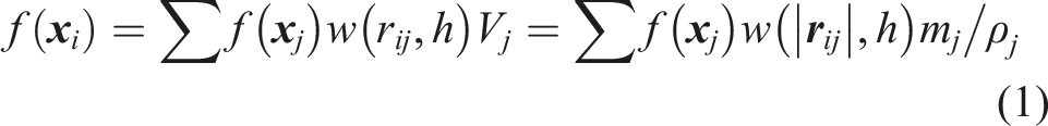

The
2.2. Discretization of governing equations
Tank sloshing is modeled through conservation laws, expressed with the material derivative (


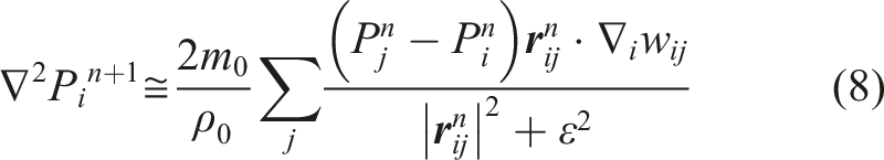
Taking the gradient of equation (6) with

A second-order approximation (Cummins and Rudman, 1999; Morris et al., 1997) is used where
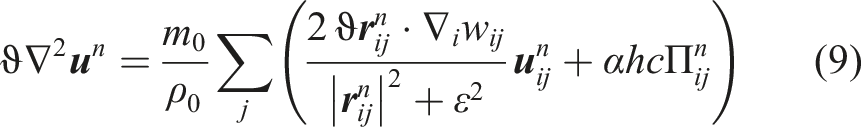
The viscosity term is formulated with
Due to the sparse, asymmetric matrix in Poisson’s equation, the Stabilized BiCG method (Dincer et al., 1996; Dinçer et al., 1994) is utilized. After computing

At the end of each time step, the particle positions are shifted slightly by the amount of
2.3. Particle classification and repositioning
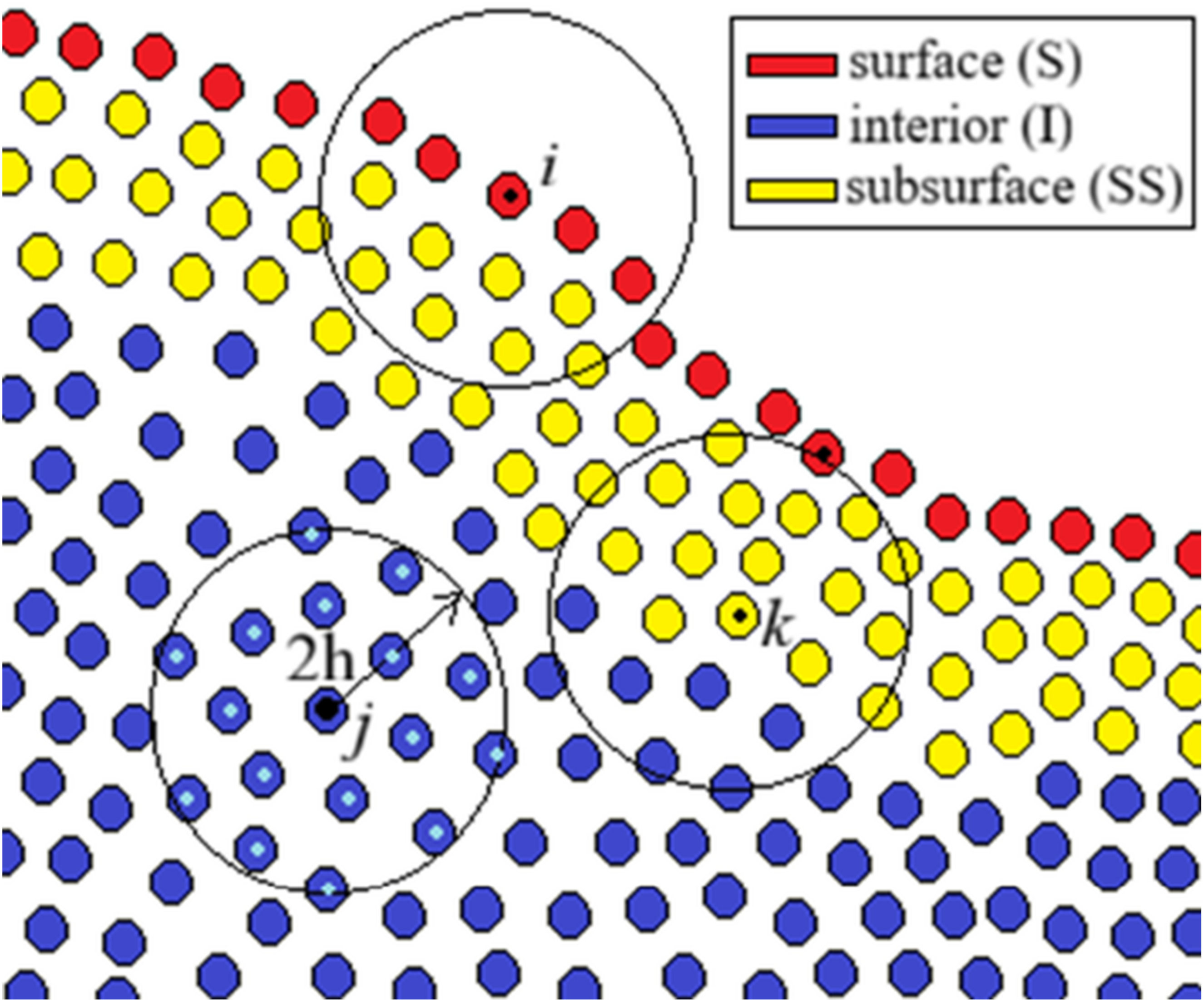
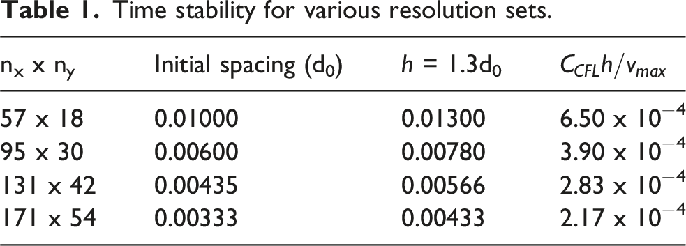
The 5th order Wendland kernel is employed. The kernel’s influence radius extends to 2h (Figure 1). With an initial particle spacing of d0, the smoothing length h is chosen as 1.3d0 within the recommended 1.3d0 to 1.6d0 range (Liu and Liu, 2003; Monaghan, 1992) to meet resolution requirements. This ensures that, under a uniform distribution, at least 14 neighboring particles lie within the influence domain of an interior particle (I). This condition is verified at each time step using the specified procedure. • Interior particles are defined and remaining particles are assigned as surface particles(S). • In the next step, if any interior particle interacts with any surface particle (as shown in Figure 1 by particle k), this interior particle is reassigned as a subsurface particle (SS). Classification of particles.
3. Validation of the code by sloshing tank test
The accuracy of the ISPH code was ensured by an experimental study (Xue et al., 2017). Initial height of the liquid is taken as 0.18 m in the prismatic tank with a length of L = 0.57 m. In these studies, excitation displacement was taken as
Time stability for various resolution sets.
At P1, the pressure history (Figure 2) was obtained by the test when 57 x 18 (d0 = 10 mm) corresponding to the weakest resolution case. Pressure values include two peak points, as in experimental results (Xue et al., 2017), the first occurs when the liquid hits the wall for the first time, and the second occurs when it leaves the wall. The maximum pressure at P1 is 1.67 kPa which is 1.42 kPa in the given experimental work. The comparison of ISPH pressure history (red) at P1 with the experimental (black) work (Xue et al., 2017), when 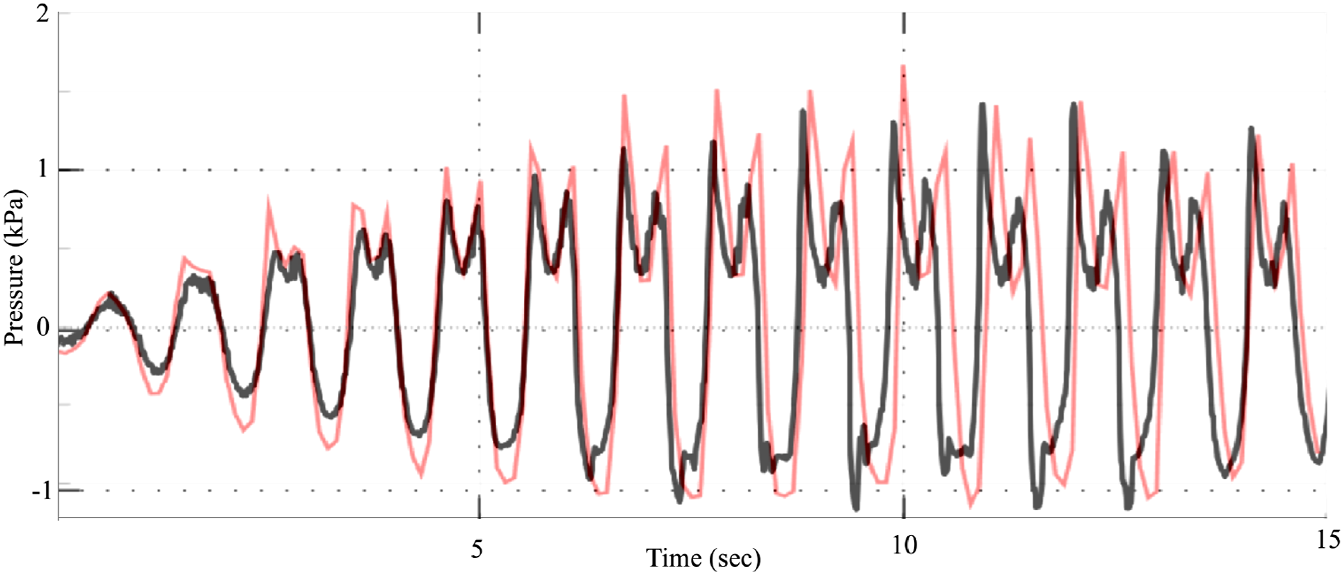
The net force is obtained on the tank by the sum of the pressure distribution on the wall surface. The difference, F
TLD
for nx x ny = 57 x 19 (black), 95 x 30 (green), 133 x 42 (red), and 171 x 54 (blue) when 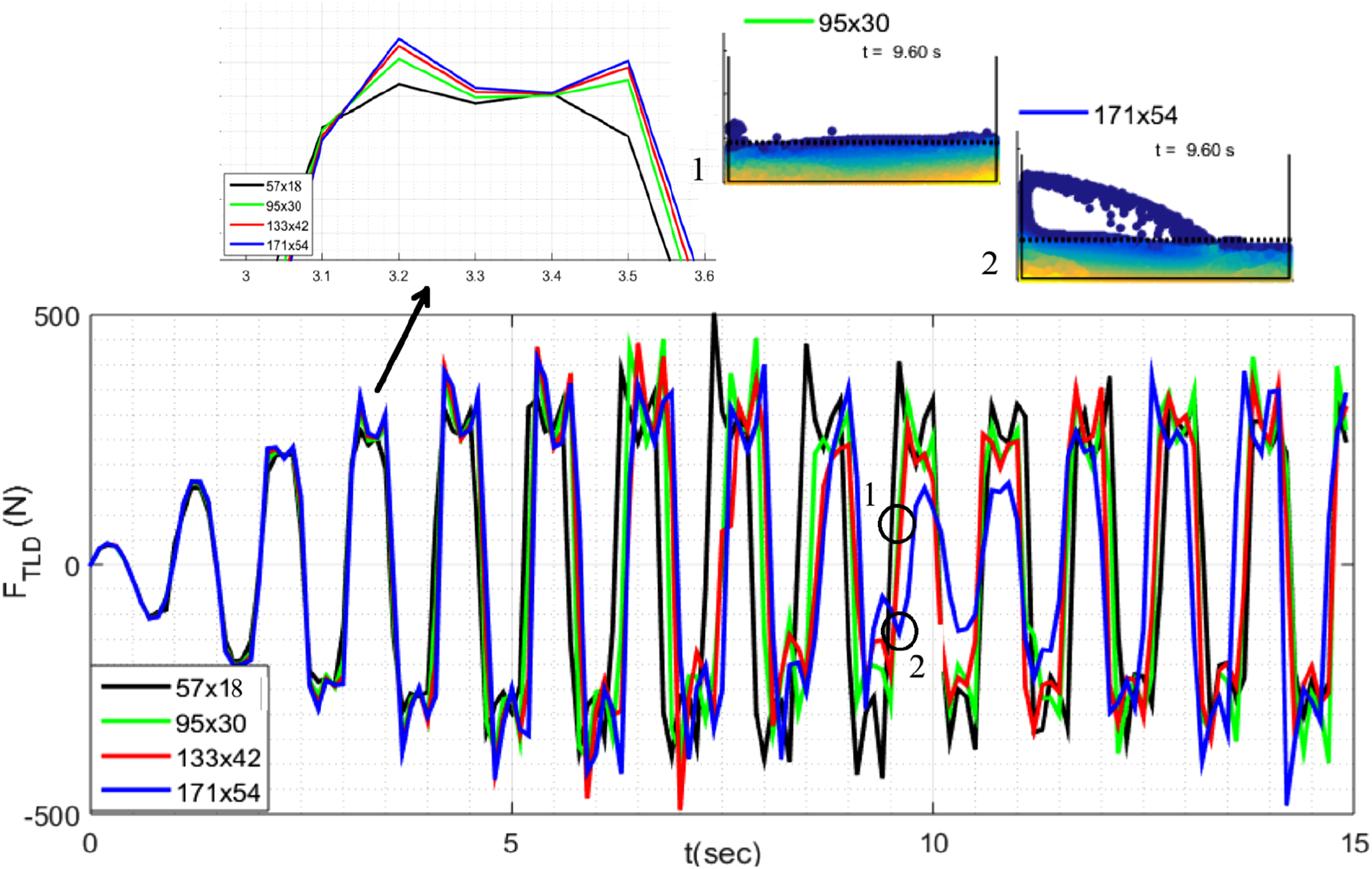
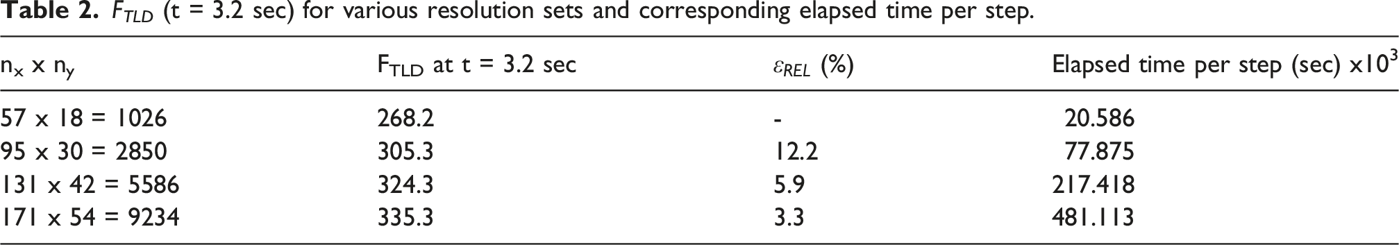
F TLD (t = 3.2 sec) for various resolution sets and corresponding elapsed time per step.
ISPH images were turned horizontally to be compatible with the experimental (Xue et al., 2017) images (Figure 4). In the experiment, the refracted waves are more pronounced. Nevertheless, a great deal of agreement was achieved with the sloshing snapshots included in the experimental study. ISPH when nx x ny = 171 x 54 (d0 = 3.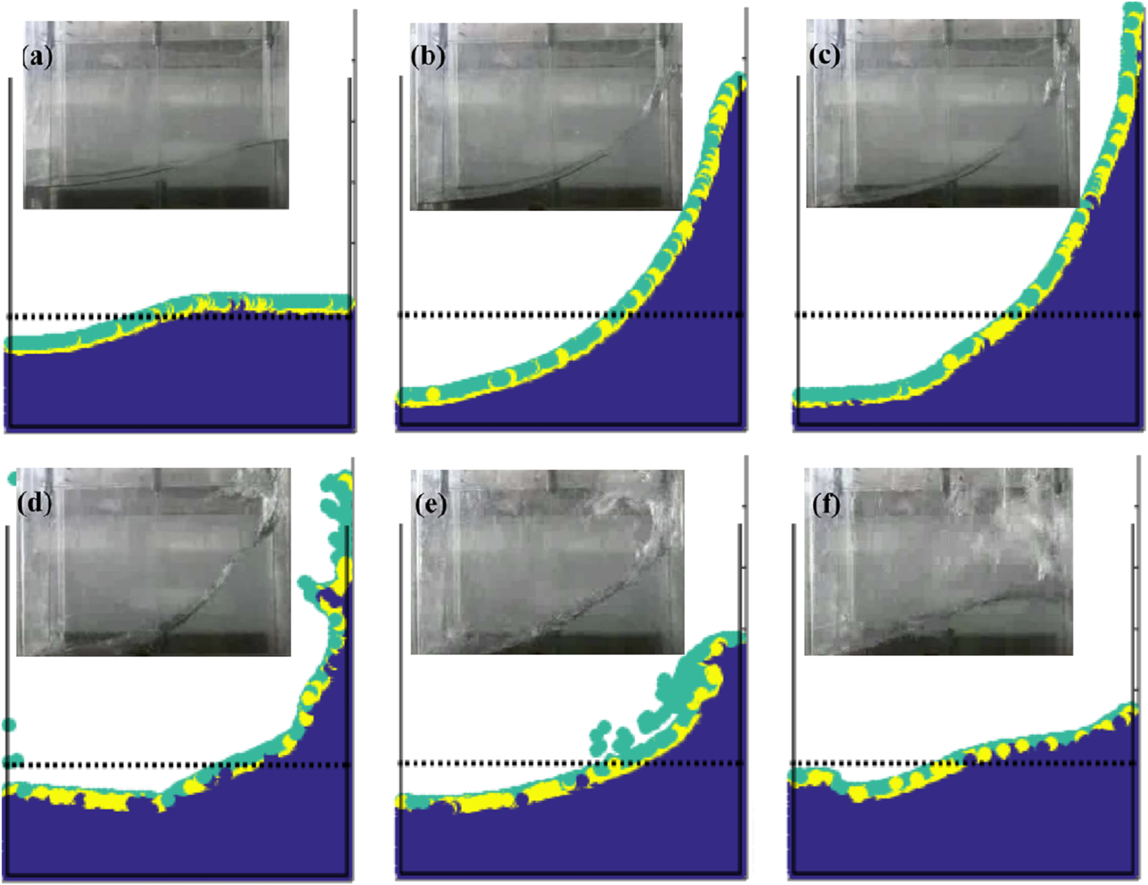
4. Modeling 3-story frame structure
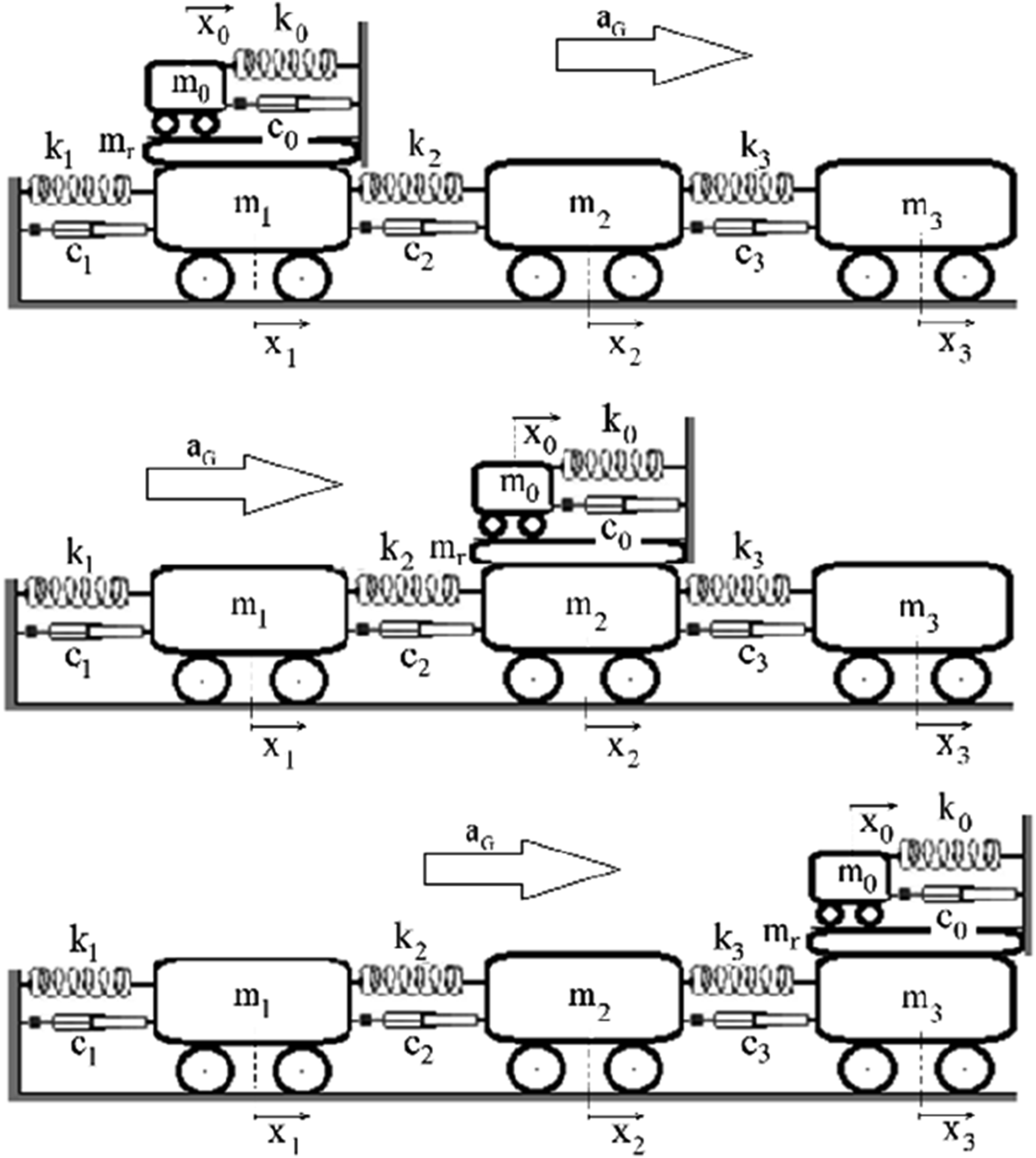
In sloshing experiments (Li et al., 2025; Vafaei et al., 2021), a tank (Lx = 0.4 m, b = 0.2 m, H = 0.12 m; H/Lx = 0.3) was mounted on a 3-story frame (Figure 5) to measure story displacements. The structure had 1 m spans, with story heights L1 = L3 = 0.8 m and L2 = 1.05 m. Beams in the excitation direction were 2 cm × 2 cm box sections, perpendicular elements 4 cm × 4 cm angles, and columns of 5 cm width with thicknesses 12 mm (1st), 9 mm (2nd), and 6 mm (3rd). Steel properties were ρ = 7850 kg/m3 and E = 200 GPa (ANSI/AISC 360-16, 2016). The total weight was ∼40 kg, plus added loads of 180 kg (1st floor) and 80 kg (3rd floor). 3-Story Frame model (Li et al., 2025; Vafaei et al., 2021).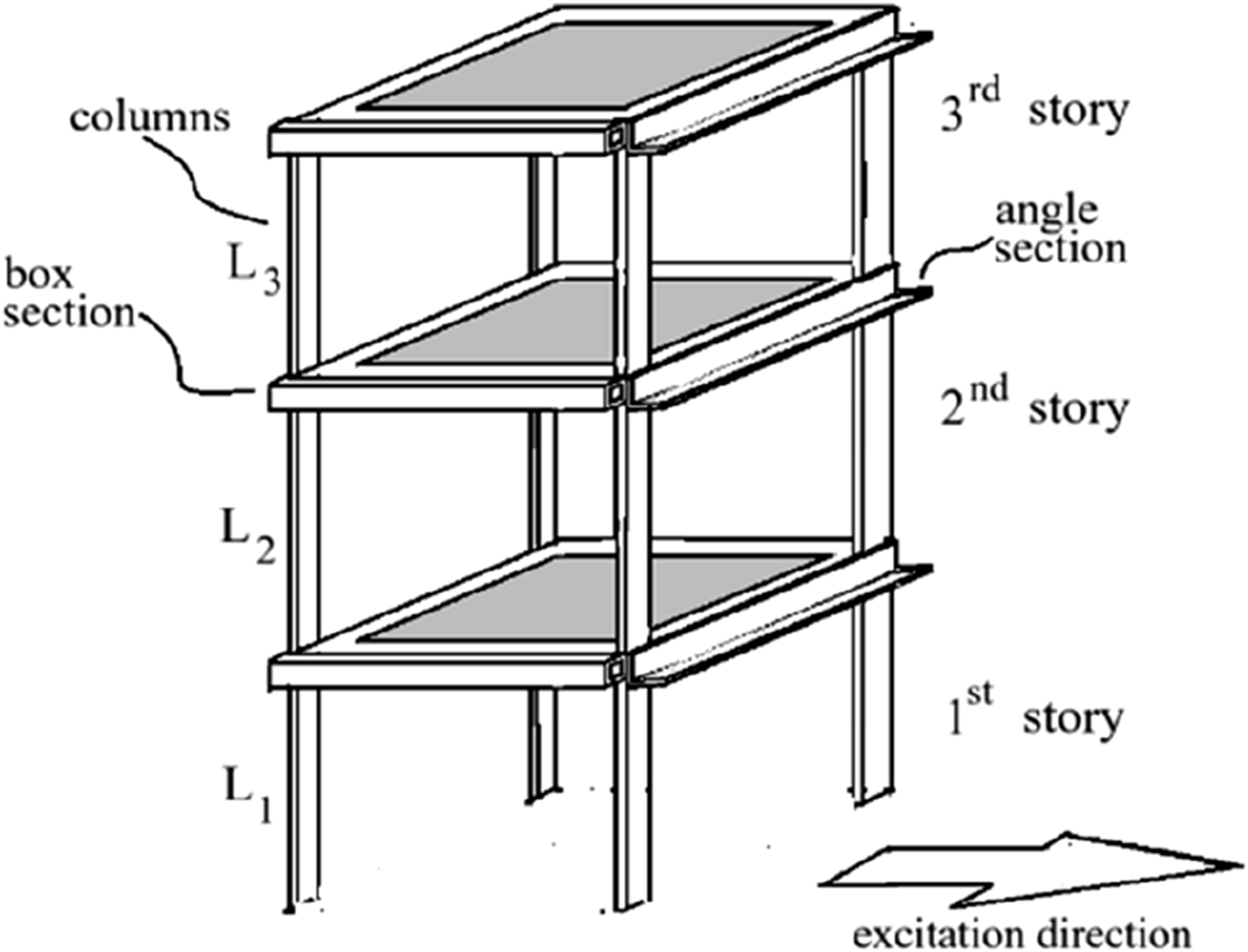
4.1. TLD analogy
This 3-storey structure is modeled as a lumped mass system (Chopra, 1995). The horizontal displacements and velocities of the stories are defined as 


The TLD acts as an auxiliary spring attached to kth mass with stiffness 
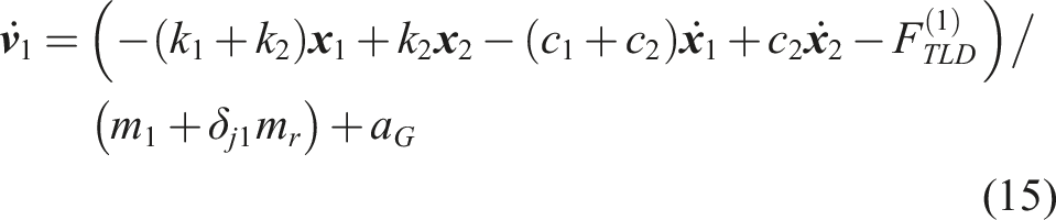
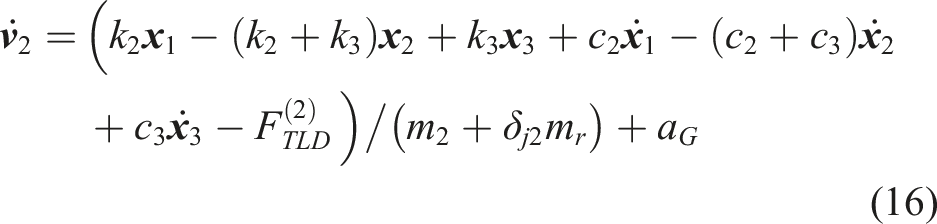
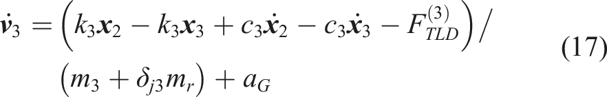
In the analog model (Figure 6), the ground acceleration is denoted as a
G
. Story stiffness, Story frame analogy with TLD system, TLD system is at 1st, 2nd and 3rd stories, from top to bottom, respectively.

The damping coefficient of the sloshing liquid 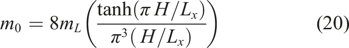
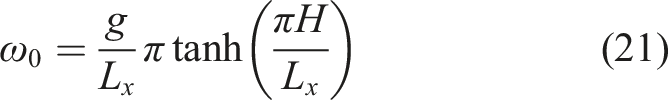
4.2. Determination of sloshing damping coefficient, ξ
0 ,L
This section determines the damping coefficient of sloshing liquid in ISPH simulations by analyzing free decay after applying 0.05 Hz harmonic displacements 0.10,0.12 and 0.14 m for 5 seconds. The free-surface elevation decays exponentially as
4.3. Calibration for the numerical models
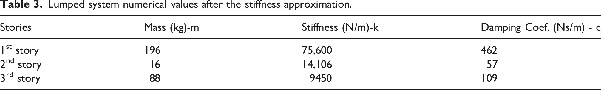
Lumped system numerical values after the stiffness approximation.
The ξ was set uniformly at 1.7% (Li et al., 2025; Vafaei et al., 2021), though slightly higher values improved agreement in the analog model. Under 1.2 Hz excitation (near resonance) without a TLD, story displacements were 9.5 mm, 51.5 mm, and 84 mm, with ground motion limited to 10 cm. The optimal damping was estimated by minimizing differences (Equation (22)) from experimental data. S reaches its smallest value when 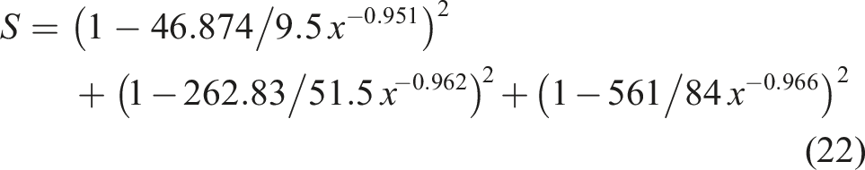
5. Tests on 3-story frame
In the tests performed with ISPH, the liquid in the tank was represented by 100 particles in horizontal direction and was taken as d0 = 0.004 m. In the vertical direction, 30 particles were used, so tests were carried out using a total of 3000 particles. The
5.1. Free harmonic motion
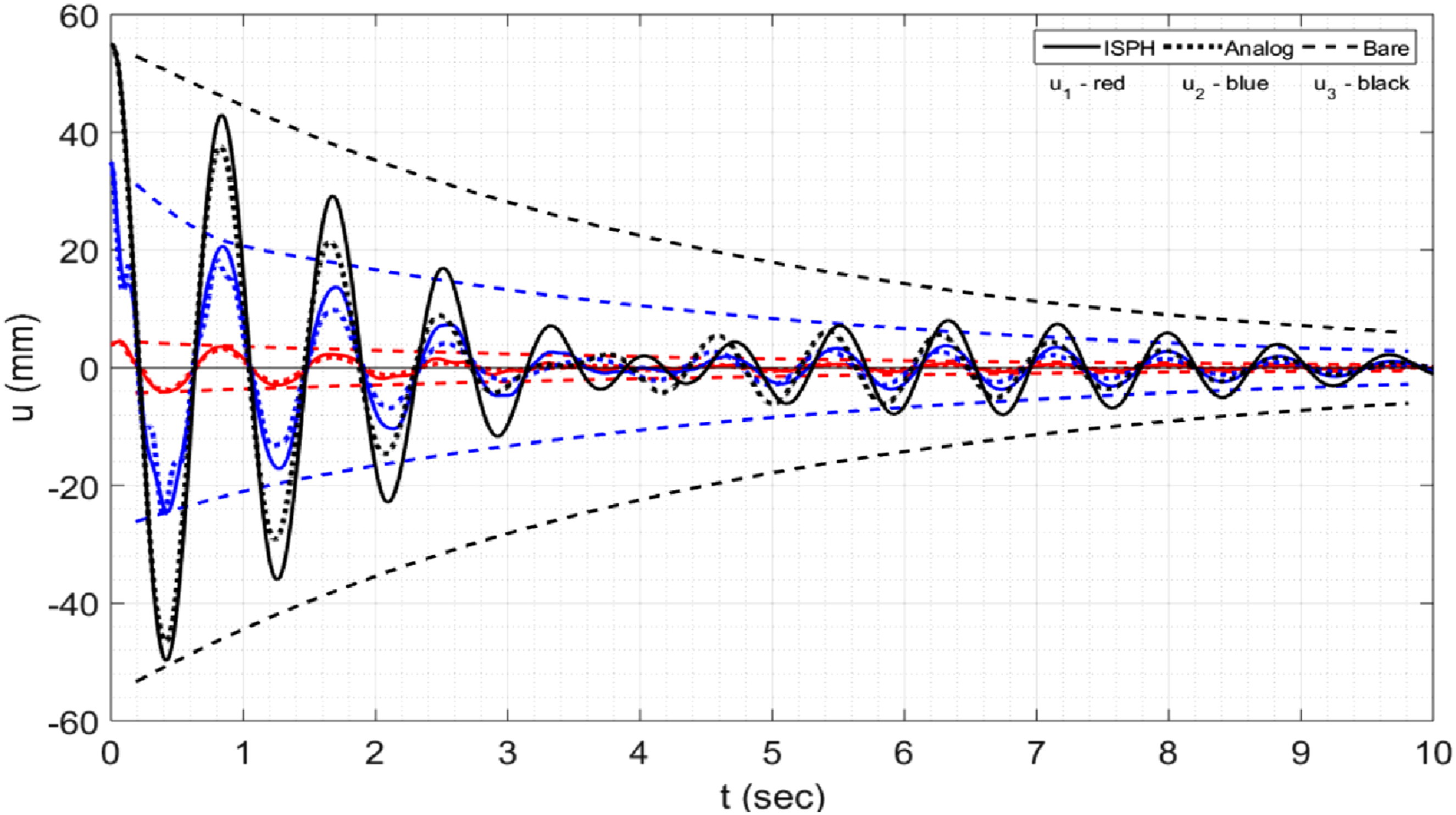
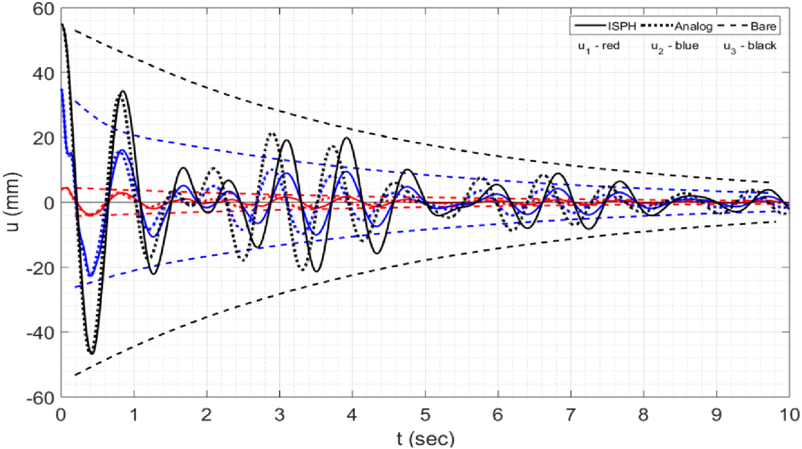
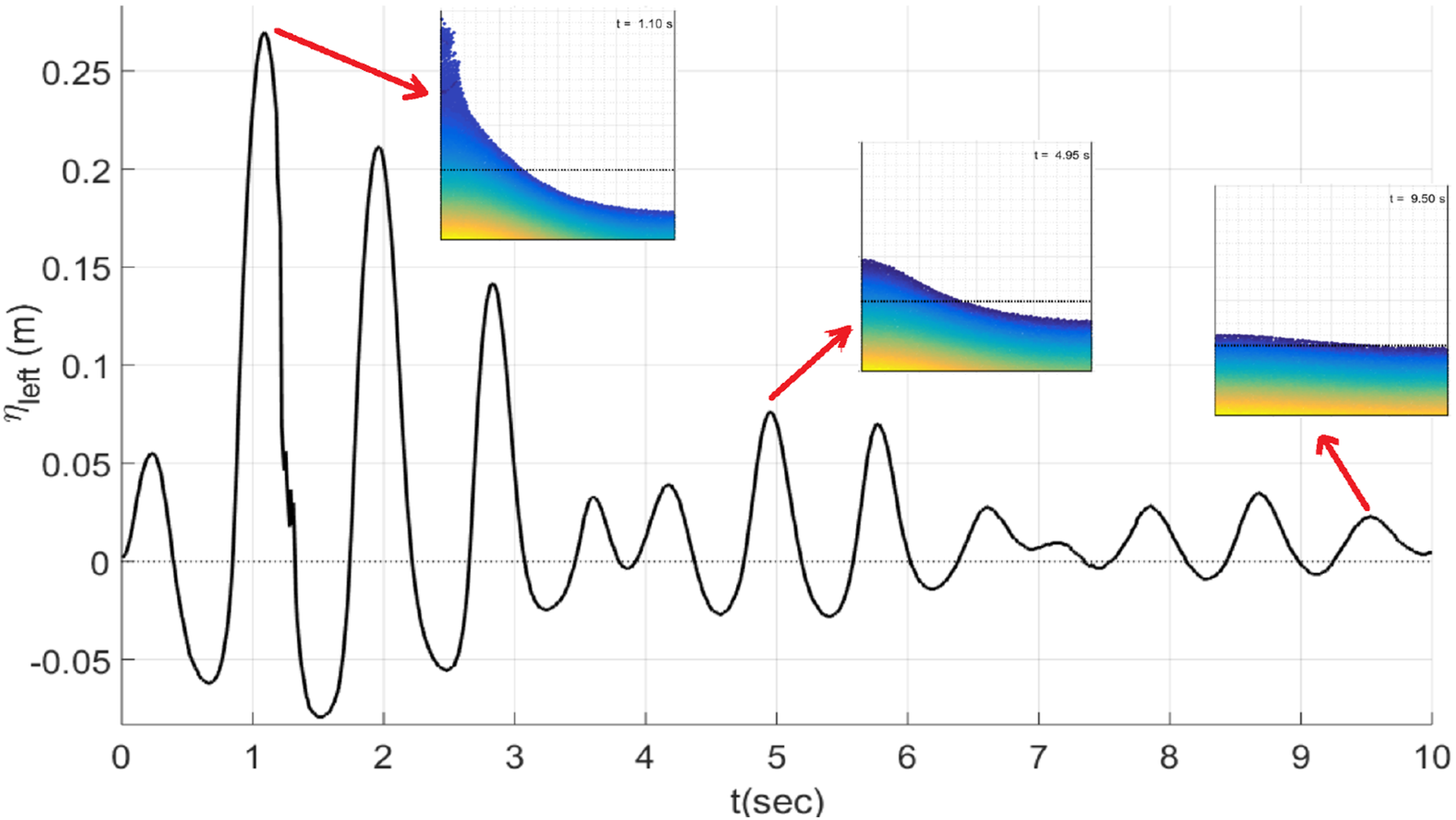
Free harmonic motion tests were run for both analog and ISPH models with initial displacements of 4 mm, 35 mm, and 55 mm for the 1st–3rd stories, released for 10 sec oscillations. In the bare frame, displacements decayed below 6 mm at t = 10 sec. With the TLD on the 1st story, damping was negligible and ISPH/analog curves overlapped (Figure 7). At the 2nd story, beating occurred: amplitudes decreased, regrew near t = 4 sec, then subsided (Figure 8), consistent with low-damping energy exchange (Yalla and Kareem, 2001). ISPH differences stem from wall-pressure modeling, while the analog model uses only the first sloshing mode. On the 3rd story, beating was stronger (Figure 9); at t = 4 sec displacements rose across all floors, with the 3rd reaching ∼27 mm (≈½ of its initial 55 mm). Temporal mismatches appeared: story peaks just before t = 1 sec vs. free-surface peaks at t = 1.05 s; between 3 and 4 sec story displacements rose while the free surface was calm; at t = 4.95 sec displacements dropped while free-surface motion increased (Figure 10). These results show sloshing-structure interaction evolves over time rather than instantaneously. Displacements of stories when TLD is at 1st story by Analog model and ISPH methods compared with the bare system (dashed). Displacements of stories when TLD is at 2nd story by Analog model and ISPH method compared with the bare system (dashed). Displacements of stories when TLD is at 3rd story by Analog model and ISPH method compared with the bare system (dashed). Free-surface level (η) on the left wall and the wave profile at instants t = 1.10 sec, t = 4.95 sec and t = 9.50 sec, in the case of free harmonic motion and the TLD is at 3rd story.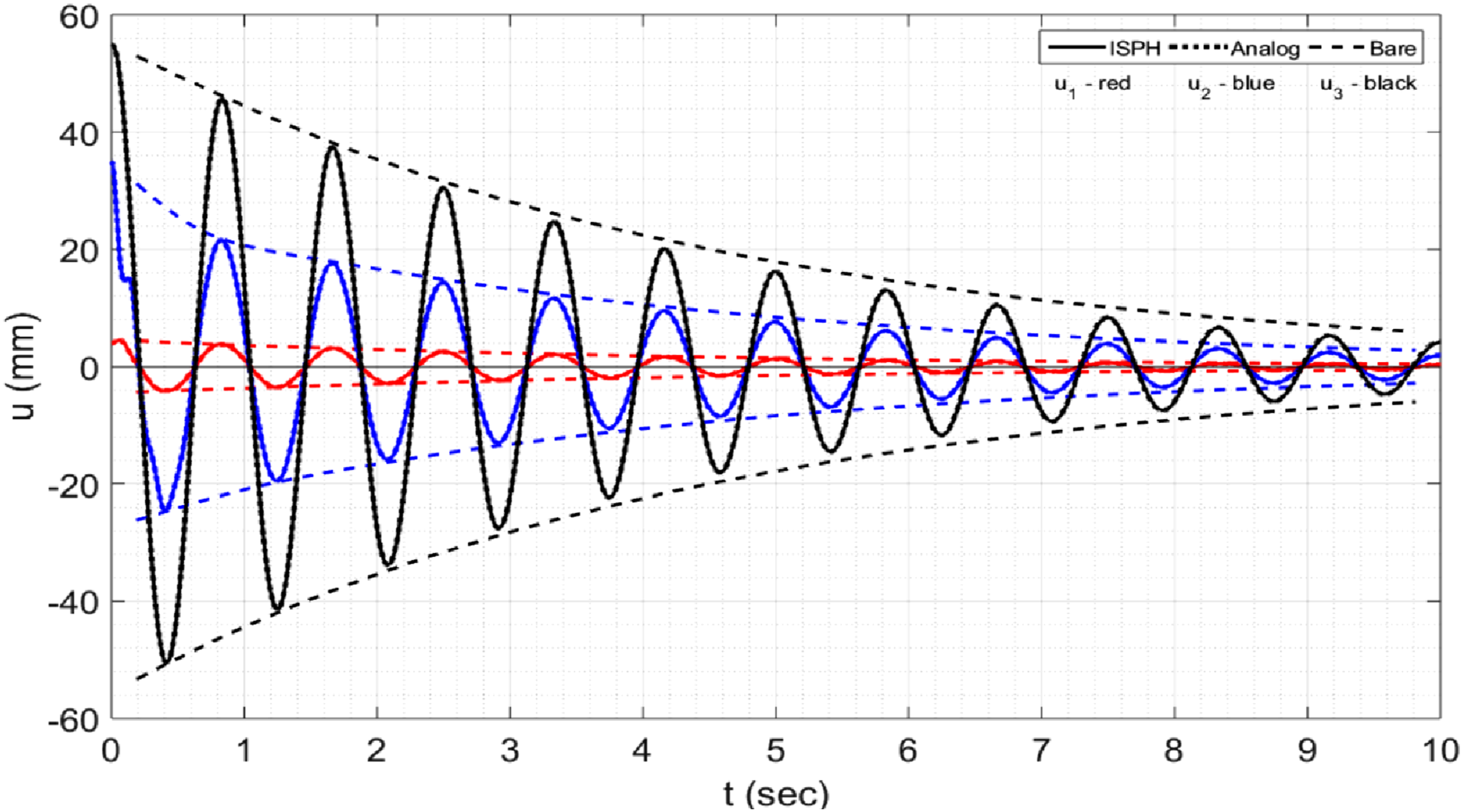
5.2. Forced harmonic motion
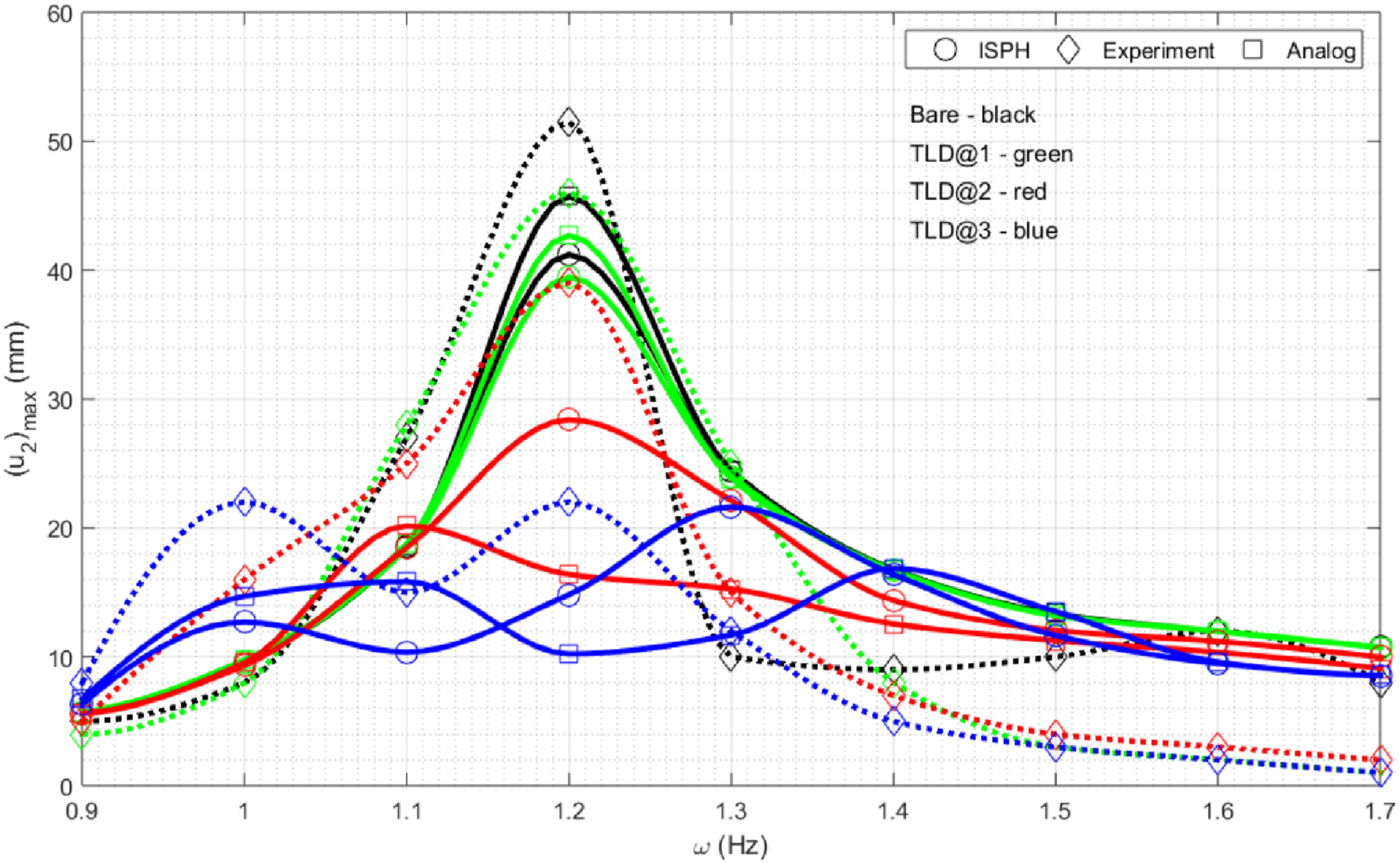
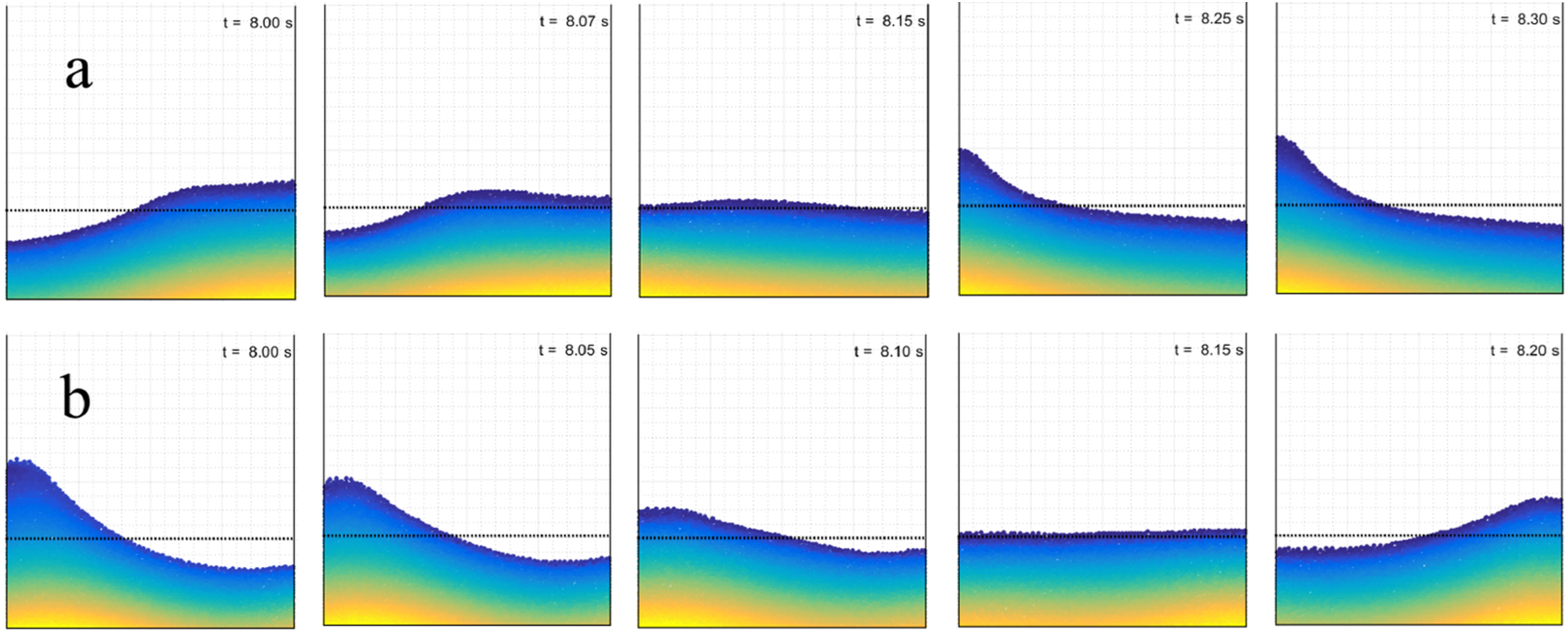
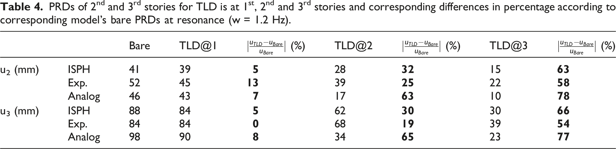
The 3-story frame was tested with/without TLDs on each story under 15 sec harmonic excitation, 10 cm lateral displacement, and 0.9–1.7 Hz frequencies (0.1 Hz steps). ISPH damping was tuned to match bare-frame Peak Response Displacements (PRDs) (Vafaei et al., 2021) of 8.4 mm, 46.2 mm, and 98 mm (Equation (22)). A 3rd-story TLD gave strongest damping (Figures 11–13): at 1.2 Hz PRDs decreased by ∼5%, 25%, and 60% for 1st–3rd stories, halving displacements even at 1.1 Hz. Eigenvectors (8.8, 48.7, 103.7 mm) confirmed largest PRD at the 3rd story, enabling stronger coupling. This was partly due to the traveling waves accompanying the standing waves and increasing the pressure on the walls (Figure 14(a)). Resonance peaks appeared at 1–1.3 Hz, max near 1.2 Hz. At 1 Hz, ISPH vs. analog differed by ∼10% (27 mm vs 31 mm), while experiments showed 36 mm (∼30% higher). At ≥1.4 Hz, both models agreed: PRDs ∼2.5 mm (1st), 10–17 mm (2nd), 21–35 mm (3rd) due to the standing waves corresponding to the first mode of sloshing, which corresponds to the ISPH model (Figure 14(b)). Largest ISPH–analog difference was ∼12% at 1.4 Hz with a 2nd-story TLD. Experimental PRDs deviated at low/high frequencies (∼1 mm, <5 mm, 10–20 mm). At 1.1 Hz, ISPH damping was stronger (22 mm vs 35 mm analog). At 1.2 Hz, PRD reductions matched experiments (Table 4), with analog showing max effectiveness (60–70%) for a 2nd-story TLD. PRDs at 1st story. PRDs at 2nd story. PRDs at 3rd story. (a) Standing and traveling waves together at w = 1.0 Hz and (b) standing waves at w = 1.4 Hz when TLD is at 3rd story. PRDs of 2nd and 3rd stories for TLD is at 1st, 2nd and 3rd stories and corresponding differences in percentage according to corresponding model’s bare PRDs at resonance (w = 1.2 Hz).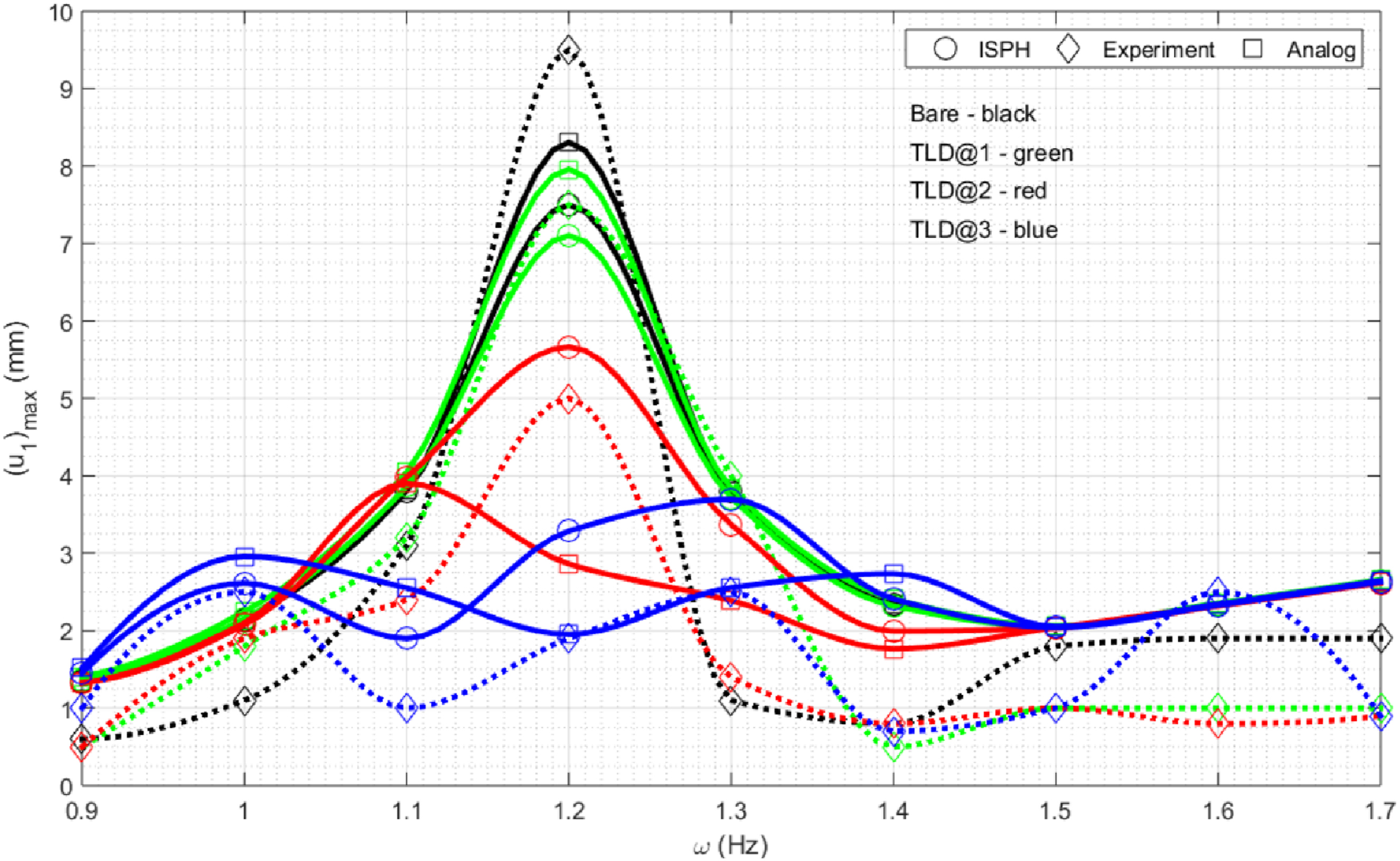
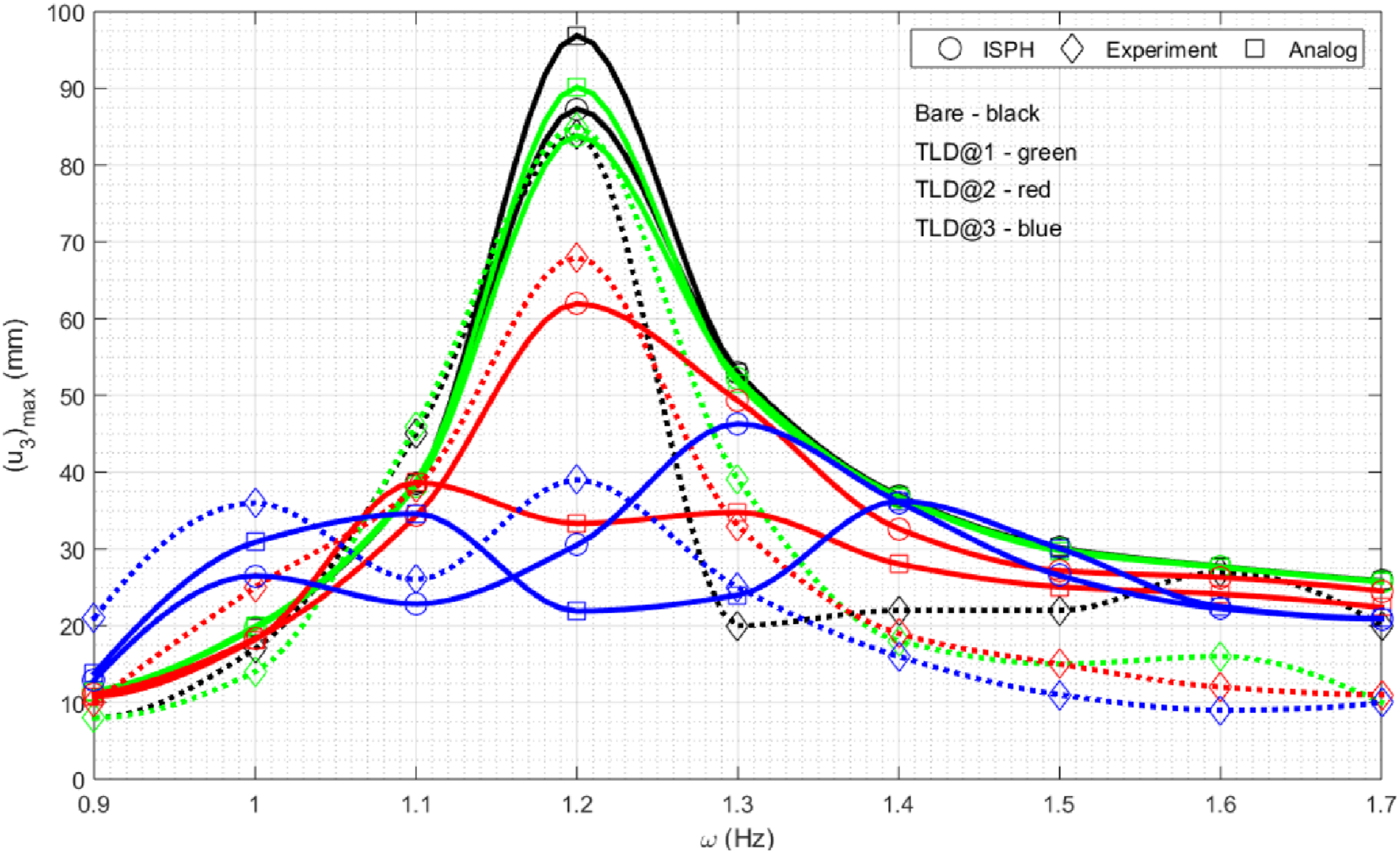
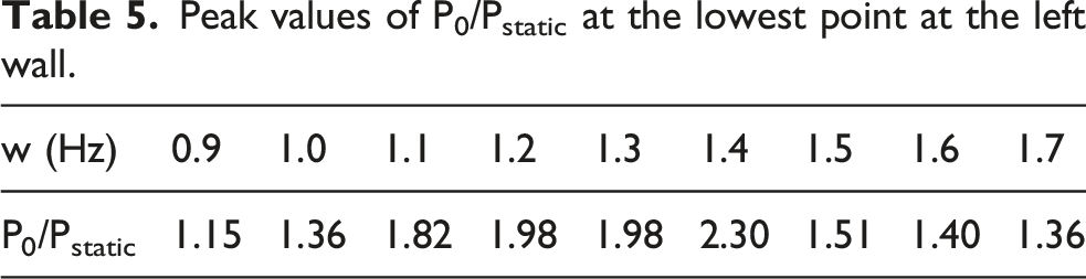
At 1.3 Hz, analog PRDs align with experiments, while ISPH shows less damping since it considers only lateral wall pressures. Sloshing at this frequency also involves breaking waves, visible in ISPH but absent in the simplified model (Figure 15). Table 5 shows pressure at the left bottom corner relative to the initial hydrostatic value (1.18 kPa); even under violent waves at 1.3 Hz, this ratio remains stable and lower than at 1.4 Hz. Thus, wall pressures alone cannot capture TLD damping—accurate modeling must include energy absorption from breaking waves. Breaking waves at w = 1.3 Hz and when TLD is at 3rd story. Peak values of P0/Pstatic at the lowest point at the left wall.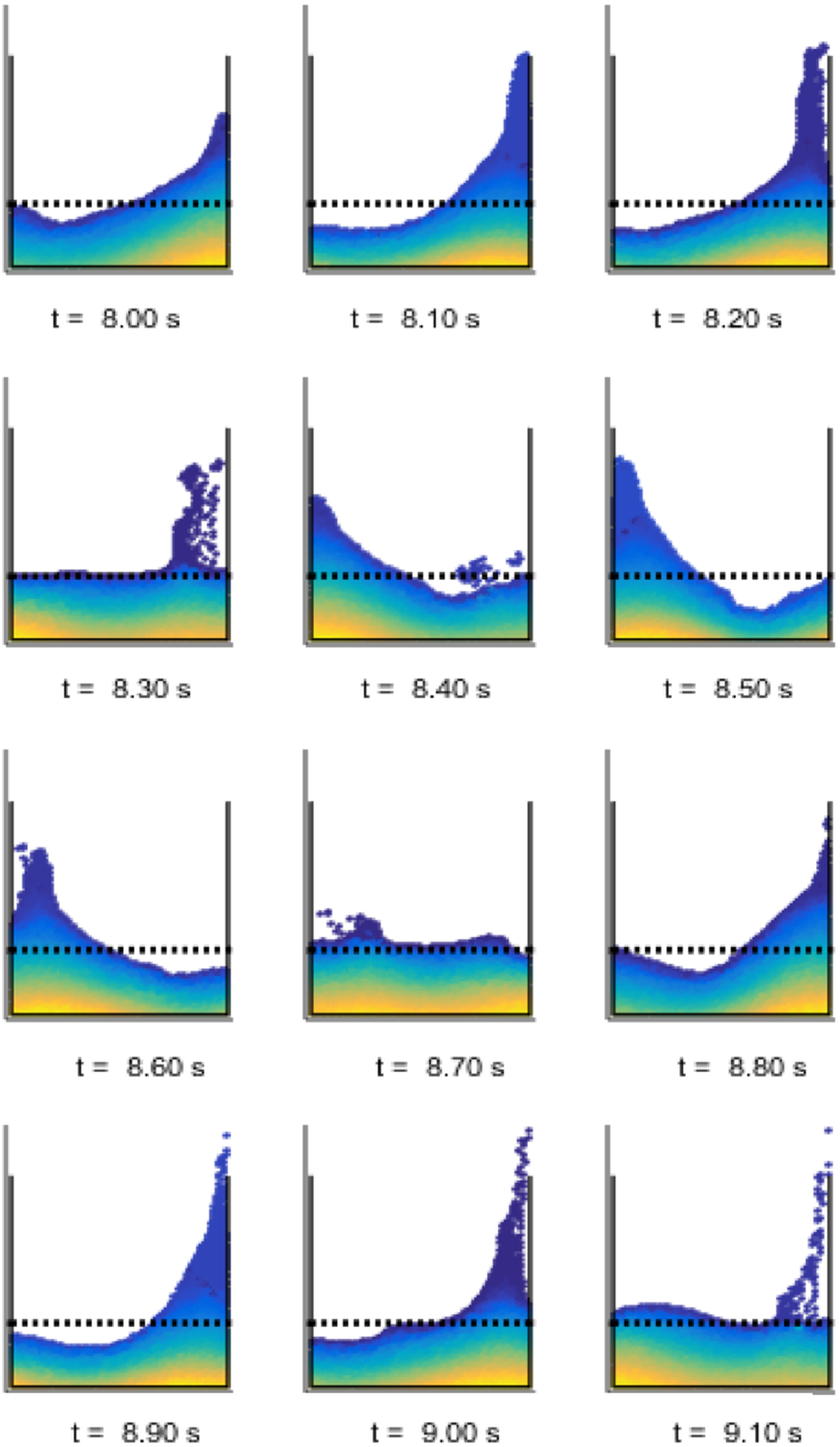
6. Comparative analysis and structural control
The calibrated analog model bridges experiments and ISPH simulations, confirming consistency and reliability for vibration control. When the exact same experimental model is taken with fixed nodes, the first natural frequency value of 1.18 Hz, which is specified in the experimental study, cannot be reached, and a higher natural frequency value of 1.61 Hz is obtained. In this study, when the stiffness and the masses of the stories are tested in various ranges, the value of 1.18 Hz and the next value 2.0 Hz cannot be reached with certainty. For this purpose, it was tried to match the structure used in the experiment with the ISPH model by reducing practically all stiffness values by 0.56, considering that all nodes of the multistorey structure used in the experiment were of similar semi-rigidity and considering that the first mode was dominant.
In ISPH, the opposing TLD force derives solely from wall pressures, while simulations reveal additional dynamics such as refracted and reflected waves. The analog model is likewise simplified, using only the first sloshing mode and excluding higher modes or breaking waves. ISPH captures rising/falling wall waves and energy-absorbing free-surface effects, evident near t = 1 sec with a 3rd-story TLD (Figures 8 and 9), though standing waves dominate overall. Temporal offsets between story displacements and free-surface motion reflect gradual energy transfer (Figure 10). Under harmonic excitation, PRDs differ from experiments and analog results since ISPH neglects bottom friction and surface effects (Figures 11–13). In fact, the pressure distribution on the base can be effective, especially in cases where there are strong nonlinear oscillations when it is close to the resonance state. Formulating this effect as a dissipation force, taking into account the agitation height of the liquid, the velocity distribution near the bottom, etc., will allow much closer results to be achieved. Apart from this, turbulence models (e.g., k-e model) can also be used. Semi-analytic studies (Koh et al., 1994; Lepelletier and Raichlen, 1988; Sun et al., 1989) attribute damping to shear friction, wall impacts, and contamination. Breaking and refracting waves must therefore be included, especially near resonance (Figure 15). Earlier work modeled damping coefficients non-linearly with free-surface elevation (Yu et al., 1999).Thus, accurate ISPH formulations require damping parameters explicitly tied to surface wave behavior.
7. Conclusions
This study demonstrates that ISPH, validated against experiments and analog models, provides a reproducible framework for analyzing TLDs in vibration control. By integrating ISPH simulations with calibrated analog models and experimental data, the work bridges numerical, analytical, and physical approaches, strengthening confidence in ISPH for practical applications. • Mechanical properties must be calibrated; with tuning, ISPH and analog results align with experiments. • Sloshing-structure interaction unfolds gradually. Energy transfer between them occurs with delay, not instantaneously. • TLD effectiveness is greatest on the 3rd story, consistent with modal analysis and is efficient around resonance.
In the ISPH model, both traveling waves and breaking waves are included. In the analog model, the sloshing is limited to standing waves only. At w = 1.3 Hz, in parallel with the increasing energy loss, there are breaking waves on the free surface. Further studies should be found out how effective these waves are in TLD damping and how large they are in energy loss compared to wall and bottom frictions. Breaking waves are seen with ISPH, but these are not available in the analog model. These observed waves participate as a plus effect in the damping mechanism, especially when it is close to resonance. However, a quantitative analysis of these waves—accounting for damping, friction, and wall pressure—is beyond the scope of this study and remains an area for future research. While refinements in damping formulations are still required, ISPH provides a robust, realistic, and experimentally consistent framework for analyzing TLD behavior in structural vibration control.
Footnotes
Acknowledgment
The author acknowledges the contributions of prior studies in sloshing dynamics and vibration control, which provided the foundation for advancing the ISPH-based modeling approach presented here. In addition, author declares that the graph of the experimental data used in this study is used to make comparisons by giving proper references which can be found in the references list.
Funding
The author received no financial support for the research, authorship, and/or publication of this article.
Declaration of conflicting interests
The author declares that they have no known competing financial interests or personal relationships that could have appeared to influence the work reported in this paper.