



Abstract
Natural ventilation improves indoor air quality and thermal comfort, but it also permits urban traffic noise, which is dominant in the low-to-mid-frequency range of 300–1000 Hz. Achieving effective noise control while maintaining a large, unobstructed window opening remains a major challenge. This study presents a retrofittable window-frame resonator array that maintains an open area of over 70%, significantly higher than those of previous low-to-mid-frequency ventilated treatments. Helmholtz resonators tuned to 400–600 Hz were designed analytically, validated through COMSOL simulations, and experimentally tested. Two array configurations were examined: one with many compact resonators and another with fewer, large-volume resonators. Measurements in a twin-reverberation chamber under no-flow and steady-flow conditions show that the large-volume array achieves more than 6 dB of attenuation in the 500 Hz one-third-octave band, compared to about 3 dB for the compact array. The results demonstrate practical low-to-mid-frequency noise reduction without compromising ventilation or visibility.
Keywords
Introduction
Sustainable building design has renewed interest in natural ventilation as a passive strategy to improve indoor air quality and reduce cooling energy demand. Residential buildings account for a significant share of global energy use, around 20%–30%, in maintaining thermal comfort for occupants. 1 However, the use of open or partially open windows often comes at the cost of reduced acoustic comfort, especially in urban areas exposed to road traffic noise. This creates a natural ventilation–noise control trade-off, where the openness required for ventilation also reduces the ability of the window system to block outdoor noise. Recent studies have highlighted the importance of addressing ventilation and acoustic performance together in the design of window systems.2,3 Since road traffic noise forms a major part of urban noise pollution, 4 developing practical acoustic treatments for naturally ventilated windows, without significantly reducing the ventilation area or visual openness, remains an important challenge in sustainable building acoustics.
Higher noise levels ranging from 70 to 90 dB can lead to sleep disorders, stress, distraction, hearing damage, and other health issues.5,6 In a study conducted in a large metro city, the noise levels in many areas were found to vary between 75 and 90 dB. 7 This is primarily due to traffic, and the dominant frequencies are typically between 500 and 1000 Hz 8 ; low-to-mid-frequency noise control is challenging as one has to deal with longer wavelengths, which travel more distances with minimal decay, contributing significantly to the noise reaching the residents. 9 Channelling the sound through ducts or pathways and treating these pathways with absorptive materials or coiled-up resonators 10 can be more effective in an industrial setting where space may not be a critical constraint and direct line of sight is not required.
A comprehensive review of ventilated acoustic metamaterials has been presented by Ang et al. 11 Several concepts have been explored to achieve simultaneous airflow and sound attenuation, including labyrinthine and space-coiling designs in which the opening is connected to side branches composed of twisted pathways. 12 Although such concepts can provide appreciable sound attenuation, the effective ventilation area is often small relative to the total structure, and multiple units are generally required to form metapanels 13 or metacages for ventilated noise control. 14 Some of these metapanel-based concepts have also been adapted for window and façade applications. Other approaches based on Fano-like interference have also been reported,15,16 where destructive interference between direct and scattered sound paths is used to reduce transmission. However, many of these concepts remain bulky when scaled to practical sizes, with the scattering structures occupying a considerable portion of the available ventilation area. 17 More recent studies have further extended these ideas to window-scale systems using sub-wavelength resonators, including ventilated acoustic metamaterial window panels and metamaterial-based open-window concepts that evaluate both sound insulation and natural ventilation together.18,19 In this context, while resonator-based window concepts are promising, their practical applicability to residential windows depends strongly on how effectively they preserve open area while maintaining useful attenuation. This provides context for the present study, where retaining a large opening area for ventilation while reducing sound transmission is a primary consideration.
In residential buildings, more conventional strategies for mitigating traffic noise include the use of specialized façade designs,
20
plenum windows,
21
active noise control techniques,
22
and balcony-based noise shielding concepts.
23
In recent years, research efforts have extended to larger-scale applications, targeting full-size window openings by replacing conventional windows with innovative designs, such as complex origami-inspired window structures
24
and plenum windows integrated with micro-perforated panels.
25
Subsequent developments focused on more practical solutions that preserve the visual transparency of windows. One such design, analogous to metapanels but considerably less complex and fabricated from transparent glass, targets the frequency range of 700–2500 Hz.
26
To date, the most practical and minimally invasive configuration capable of replacing a conventional window while providing sufficient opening is a
This research is motivated by the need to achieve low-to-mid-frequency noise mitigation using large, minimally intrusive ventilation openings, while preserving the visual transparency of windows. Although these objectives are inherently challenging, the proposed approach adopts a simple design philosophy with the flexibility to target arbitrary frequency ranges and the scalability required for retrofitting windows of varying sizes. The proposed design philosophy involves constructing a resonator array composed of multiple resonators tuned to distinct frequencies, mounted within a frame that encircles the perimeter of an existing window. This configuration ensures that the effective open ventilation area is preserved, with only a minimal reduction relative to the original window opening. The resonators chosen for this investigation operate in a frequency range of 400–600 Hz, thereby targeting the 500 Hz 1/3rd octave band. It must be emphasized here that there is no constraint on the frequency ranges to be targeted using this design approach. Since the experimental facility used in the research has a lower cut-off frequency of 300 Hz, the 500 Hz 1/3rd octave band was chosen to ensure that the measurement errors are minimized. It will be demonstrated that larger volume cuboid resonators provide significant noise reduction compared to more compact designs at the same frequency. The cuboid design also facilitates efficient packaging within the frame assembly around the window. In this study, the ventilation area is
Resonator design and validation
A Helmholtz resonator with a rectangular cavity and a cylindrical neck is selected for the study. The selection is made considering the packing efficiency and ease of retrofitting to a window. Once the selected resonators are assembled into an array, the configuration is evaluated in a twin reverberation chamber facility. The separating aperture between the two chambers measures

Here


Schematic representation of an idealized side-mounted Helmholtz resonator connected to an equivalent duct, used for the analytical modelling of the individual resonator, showing the neck-cavity and neck-duct interfaces with the associated acoustic variables at different locations.

Schematic representation of a single resonator showing the neck diameter (
The neck-duct interface end correction factor, when mounted to a duct of radius
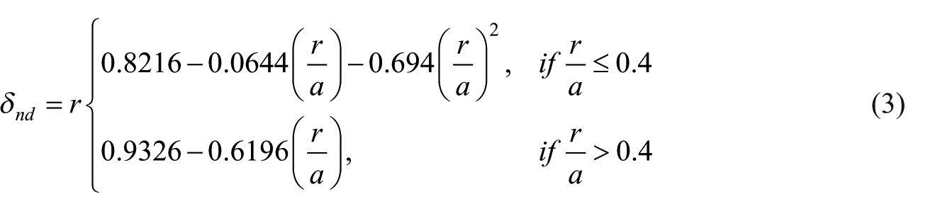
The aim of the study is to target a practically relevant portion of urban traffic noise while retaining a large open area for ventilation. Traffic noise is broadband in nature, and spectral analyses commonly include bands such as 250, 500, 1000, 2000, and 4000 Hz.
29
Within this broad range, the frequency range selected for the present study is 400–600 Hz, targeting the 500 Hz one-third-octave band, which represents a challenging yet geometrically feasible range for a retrofittable resonator-frame concept. Four resonators tuned to 440, 480, 520, and 550 Hz are selected. Resonators are constructed so that the cavity dimensions are

COMSOL Multiphysics 6.2 is used to simulate the impedance tube setup for the transmission loss study. The aim is to verify the theoretical calculations and confirm that the finalized dimensions and the resonance frequencies of the designed resonators show good agreement with the simulation results. The study is used primarily for resonator design-stage validation and tuning.
The studies are conducted using the Pressure Acoustics module to examine the individual resonators and their transmission-loss behaviour in an idealized duct-resonator configuration. A circular duct with a Helmholtz resonator mounted on the side was modelled, consistent with the configuration used in the theoretical analysis, as shown in Figure 3. Sound hard boundary is chosen to define the fluid-solid interface. Ports are used on either end of the tube for measurement of properties. One end is excited with 1 Pa pressure, and power is measured at the outlet and inlet. The power transmission coefficient is calculated from the model

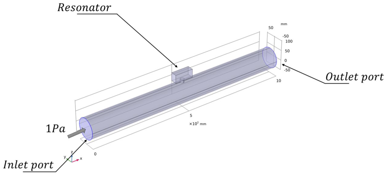
COMSOL multiphysics model of an impedance tube setup with a side-mounted Helmholtz resonator.
A frequency sweep is performed from 400 to 600 Hz with a step of 1 Hz. An extremely fine mesh is used in transmission loss calculation with a maximum element size of 20 mm (
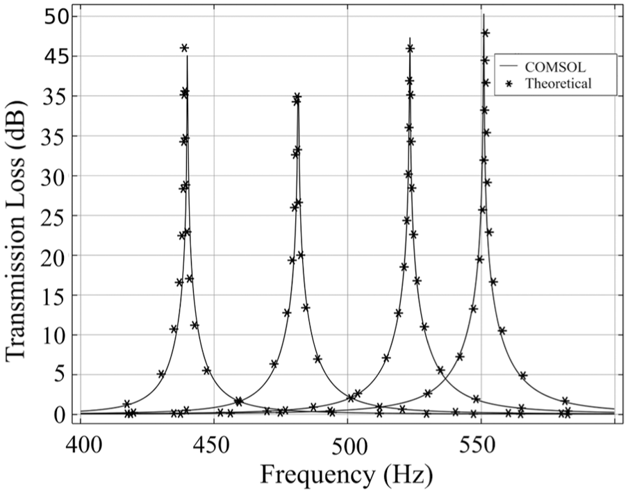
Comparison of theoretical predictions and COMSOL simulation results for transmission loss of individual Helmholtz resonators. Each curve corresponds to a separate resonator tuned to a different frequency, plotted independently in a single figure for comparison.
Experimental investigation
Once the designs have been finalized, the resonators are fabricated. An individual resonator is tested in an impedance tube to identify the natural frequency in a controlled normal incidence environment; this also helps validate the design process. After validation, an array of resonators is assembled and tested in the twin reverberation chamber facility, as it provides insight into a diffuse field environment.
Single resonator studies
Individual resonators are 3D printed using Fused Deposition Modelling (FDM). Material used for fabrication is poly lactic acid (PLA) with 0.15 mm layer height and 100 % infill density with a wall thickness of 3 mm to ensure a rigid construction. The experiment is carried out on a BSWA SW 422 100 mm diameter impedance tube system. The test is performed based on a standing wave ratio-based method as per ISO 10534-1 standards 32 and the transfer matrix method as per ASTM E1050-08 and ASTM E2611-09 standards. 33 The experiment is performed for the frequency range of 250–1600 Hz. Two 1/4″ microphones, one 50 W power amplifier, MC3242 four-channel data acquisition card, and VA-LAB 4 software for data processing are used. Each microphone is calibrated before experiments using a sound calibrator. Five readings are taken and averaged to ensure repeatability. The aim of this experiment is to verify that the resonance frequencies of the fabricated HRs are in good agreement with the analytical and FE results. Figure 5 presents the magnitude of the normalized reactance for the individual resonators, plotted for clearer visualization of the resonance location. The fabricated resonators exhibit a small deviation from the theoretical design, with resonance-frequency errors in the range of about 2.2%–3.1%, as summarized in Table 1. This small difference may be attributed to fabrication tolerances, minor leakage during fixing, and experimental uncertainty. Nevertheless, the shift does not significantly affect the targeted 1/3rd octave band.
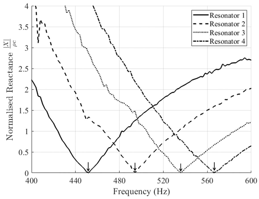
Magnitude of the normalized reactance of individual resonators measured in the impedance tube. The experimentally observed resonance frequencies are indicated by downward arrows (↓).
Deviation between analytical and experimental resonance frequencies.

Resonator array studies
One array module, as shown in Figure 6, is constructed from the four resonators, and these array modules are used to build different configurations. Resonators with a rectangular cavity are considered with the packing efficiency of the resonator in mind, utilizing all the space available. Many iterations were done to finalize the size and shape of the resonators. Resonators are constructed so that the cavity dimensions of

3D CAD model of the resonator array module comprising four resonators arranged in series within a shared housing (overall length 427 and height 73 mm).
Neck length (in mm) and the natural frequencies of the designed cuboidal resonators.
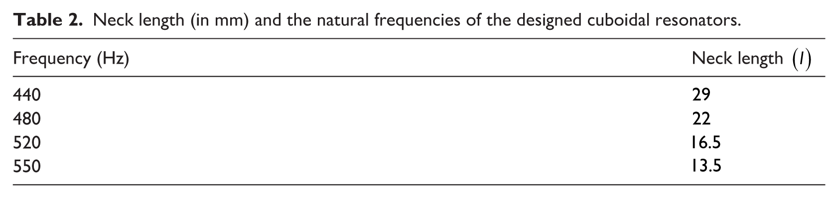
The number of resonators in the array module in the present study was limited to four because of the opening dimensions of the twin reverberation chamber. The arrangement was chosen to retain as much open area as possible within the tested aperture. In this setup, even after fixing the sample, approximately 70% of the total opening area remains available for ventilation, corresponding to a clear opening of
A twin reverberation chamber, comprising two closed parallelepipeds with no two parallel walls, is employed to test the resonator array. This design, which features pentagons, leads to multiple reflections and achieves a near-diffused field. The chamber used in the present study is an existing in-house facility originally designed based on the relevant ISO 140-1
34
and ISO 140-3
35
series provisions applicable at the time of its construction, including a volume difference of more than 10% between the two chambers. Glass wool is used as insulation between the inner and outer layers of plywood for the construction of walls. The chambers have a cutoff frequency of 315 Hz. White noise was generated in the larger chamber using an Infra Qsources omnidirectional mid-frequency 12-driver sound source, specified by the manufacturer as satisfying ISO 140,32,35 ISO 3382
36
and ISO 16283-1
37
standards. The study uses six 1/2″ capacitive pressure transducer microphones of 50 mV/Pa sensitivity (Microtech Gefell-MKS 231 E) with a random incidence response for correct measurement in diffused and reverberant sound fields. Three microphones are kept in the source chamber, and other three are kept in the receiver side. Figure 7 shows the microphone positions and the experimental setup. Readings are taken from the microphones, and the data are averaged. The sound transmission loss (

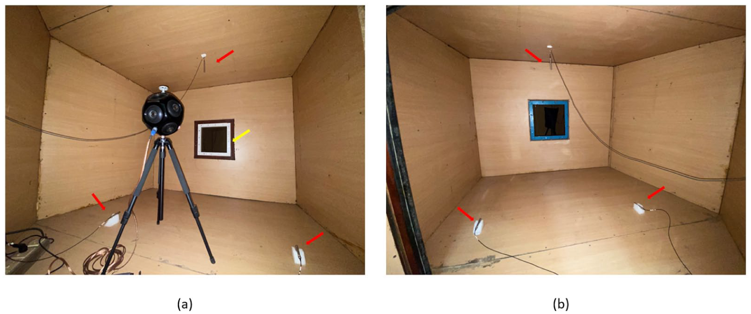
Source room (a) and receiver room (b) of the twin reverberation chamber setup, the red arrows indicate microphone positions, and the yellow arrow marks the location of the resonator array sample.
The resonator array is tested for two conditions:
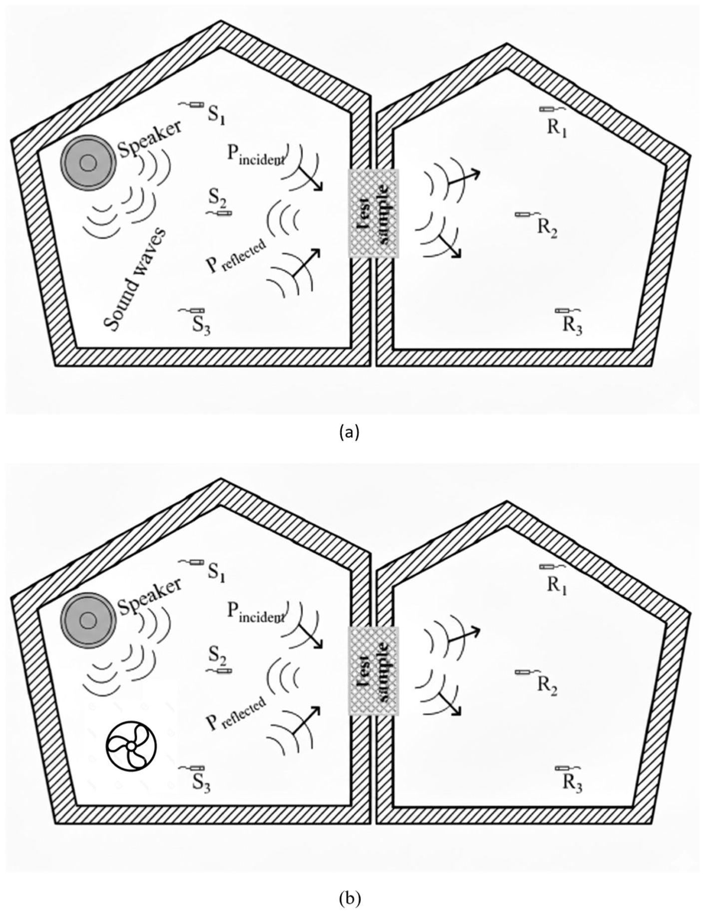
2D schematic representation of the twin reverberation chamber setup: (a) source room with omnidirectional speaker and microphones (
Four different configurations of a two row resonator array, as shown in Figure 9 are studied. The configurations are,
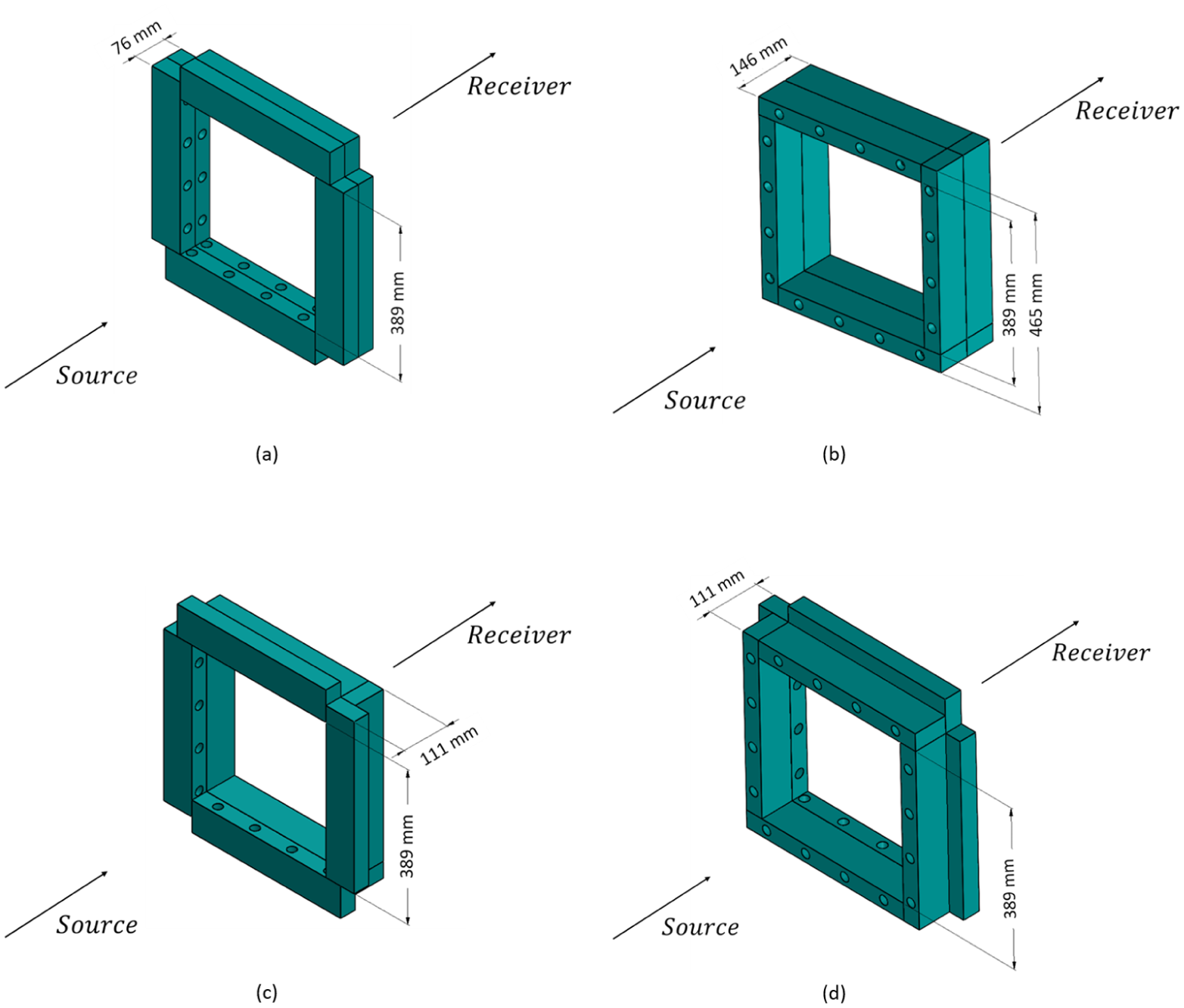
3D CAD models of the four resonator array configurations used in the twin reverberation chamber experiments: (a) GSGR, (b) NSNR, (c) NSGR, and (d) GSNR.
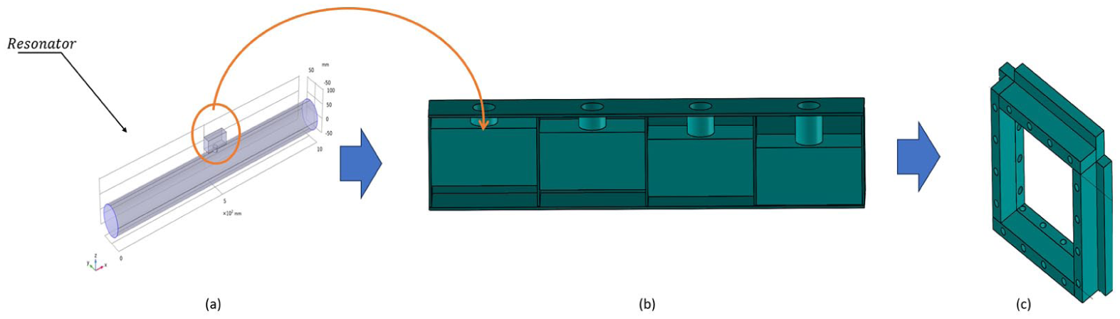
Translation of the analytical resonator concept to the experimental implementation. From left to right, the figure illustrates: (a) the idealized side-mounted Helmholtz resonator connected to an equivalent duct used for analytical modelling and tuning of an individual resonator; (b) modular implementation of resonators tuned to four target frequencies and arranged in a linear configuration; and (c) assembly of multiple resonator modules around the perimeter of the opening to form the window-frame resonator array used in the experiments.
Effect of resonator volume on array performance
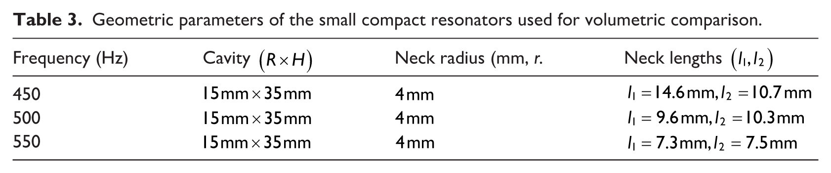
Prior to finalizing the resonator shape and size discussed in the previous section, an array using compact size resonators was thought of. This consisted of 78 compact resonators, with 26 resonators tuned to each of the frequencies 450, 500, and 550 Hz. The measured one-third octave transmission loss (TL) improvement for the four array configurations—GSGR, NSNR, GSNR, and NSGR were 2.6, 2.2, 2.2, and 2.5 dB, respectively. The compact array only provides a modest improvement in the 500 Hz one-third octave band. Table 3 shows the dimensions of the compact resonators. The selected resonators had an intruded neck to target a small frequency with a limited size, where
Geometric parameters of the small compact resonators used for volumetric comparison.
The low TL of the compact resonators was very likely due to the low volume of each resonator in the array and also lower overall array volume available for sound absorption. Hence a larger resonator as outlined in the previous section was designed and used in the array. This design utilized 32 resonators, with 8 units tuned to each target frequency. Table 4 highlights the individual and array cavity volumes for the compact and large resonator designs. While the individual cavity volume of the larger resonator is about 4 times that of the smaller resonator, the total volume is almost twice as that of the compact resonator array. The 1/3rd octave transmission loss improvement for the four configurations were 6.1 dB for GSGR, 5.9 dB for NSNR, 6.3 dB for GSNR, and 6.1 dB for NSGR. These results indicate a substantial improvement relative to the small-volume array. Overall, the findings demonstrate that increasing both the individual resonator and total array cavity volume has a strong positive effect on attenuation, even when the total number of resonators is reduced.
Comparison of volume performance trends for the two resonator variants.

A larger cavity volume provides lower reactive impedance, making the larger resonator acoustically more compliant than the smaller resonator, whose cavity volume is approximately one-fourth that of the larger design. As a result, the smaller resonator behaves as a stiffer and more highly damped element. Since the neck diameter of the smaller resonator is one-sixth that of the larger resonator, it also experiences higher viscous resistance, which further reduces its effectiveness. Because the window acts as a large acoustic port between two diffuse fields, each resonator may be considered as a shunt acoustic pathway across the opening. In this case, the performance depends not only on the acoustic impedance of the resonator, but also on how effectively it is acoustically coupled to the overall window opening. The larger resonators provide higher effective acoustic admittance and a stronger interaction with the opening area, allowing them to exchange more acoustic energy and achieve greater transmission loss even with fewer resonators. Figure 11 shows a comparison between the compact and large-volume resonator arrays for the GSGR configuration, demonstrating the notable improvement in the 500 Hz 1/3rd octave band. Other configurations show similar characteristics. Based on this observation, larger cavity resonators provide better transmission loss improvement than compact resonators.
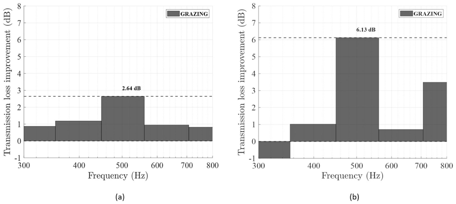
One-third octave transmission loss improvement under GSGR for the small-volume (a) and larger-volume (b) arrays. The large-volume array achieves more than double the improvement due to increased cavity volume.
Wind effect on array performance
Figures 12 and 13 show the transmission loss (TL) improvement for the four configurations under three experimentally imposed airflow conditions. Airflow was generated using a pedestal fan placed at a distance of 1 m from the sample in the source-side reverberation chamber. The air velocities were measured using a hot-wire anemometer and were approximately 0.7 m/s (speed 1), 1.1 m/s (speed 2), and 1.5 m/s (speed 3) at the window plane. The no-flow case is also overlaid on the same 1/3-octave band data for comparison. Under diffuse-field conditions and in the absence of flow, the resonator impedance is not expected to vary significantly with configuration, and only marginal differences are observed among the tested cases. Accordingly, all configurations exhibit similar acoustic behaviour under no-flow conditions, with a TL improvement of more than 6 dB in the 500 Hz 1/3-octave band.
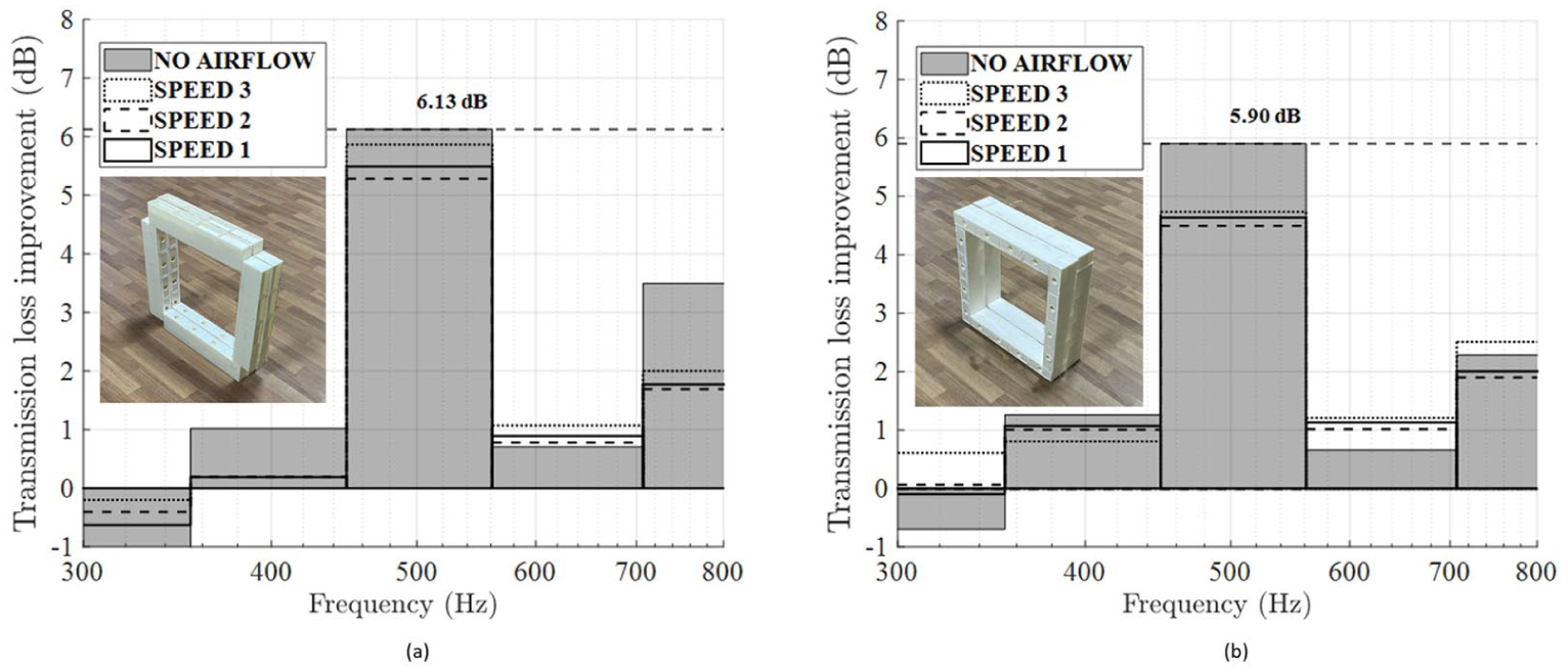
TL improvement under flow and no-flow conditions, (a) GSGR (Grazing-Source-Grazing-Receiver), (b) NSNR (Normal-Source-Normal-Receiver).
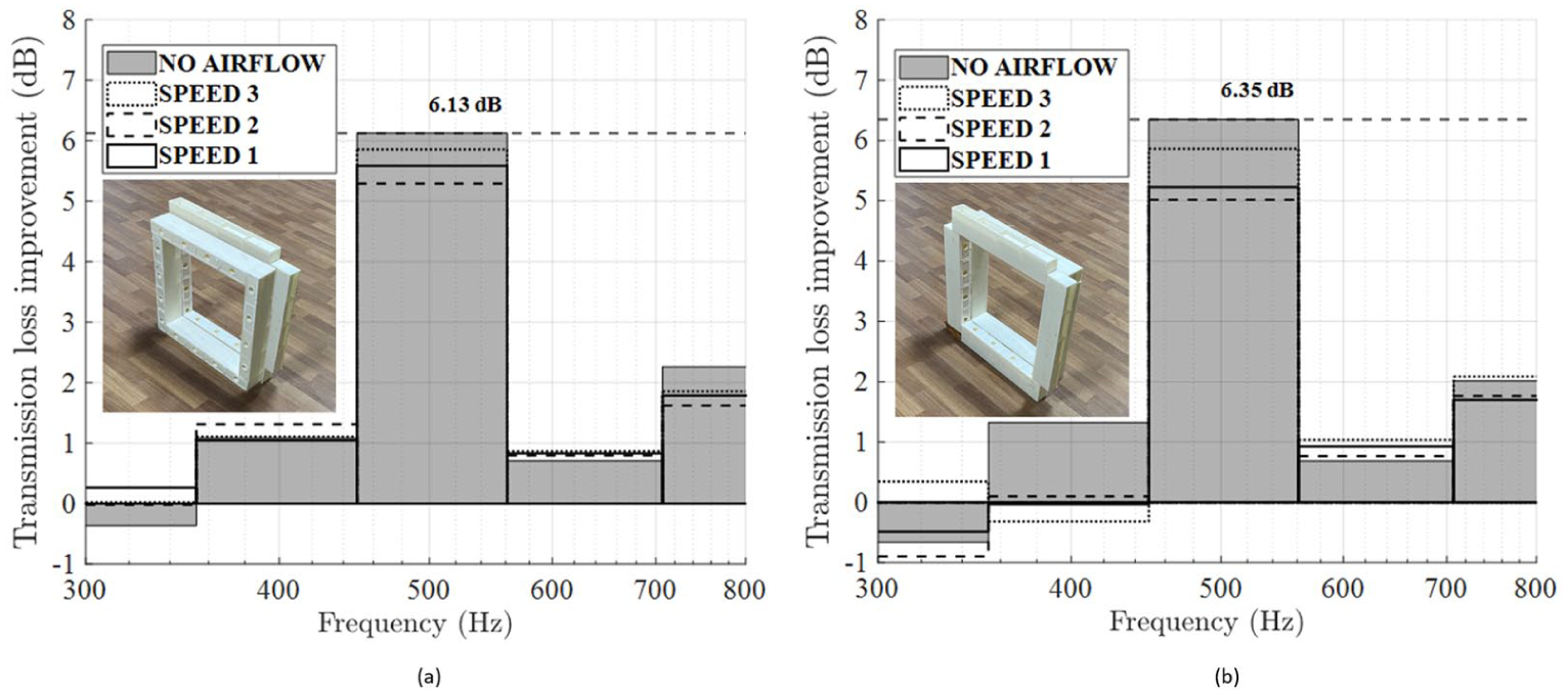
TL improvement under flow and no-flow conditions, (a) NSGR (Normal-Source-Grazing-Receiver), (b) GSNR (Grazing-Source-Normal-Receiver).
When airflow is introduced, a slight reduction in performance is observed compared with the no-flow case. Among the tested configurations, the NSNR configuration shows the largest drop in TL improvement, of about 1.5 dB, whereas the reduction for the other configurations remains within 1 dB. This suggests that configurations involving grazing incidence perform better in the presence of flow. A likely reason is that, in the normal-incidence arrangement, the airflow interacts more directly with the resonator neck opening, which increases flow-induced resistance and reduces the resonator’s effectiveness. On the other hand, grazing-incidence configurations are less directly affected by airflow and therefore exhibit a smaller reduction in acoustic performance.
Real-world validation study
To evaluate the performance of the proposed resonator array under more practical conditions, an additional real-world validation experiment was carried out after retrofitting the array to an existing window opening. Figure 14(a) shows the arrangement of the resonator array around an existing window opening in the lab. It must be noted that this experiment was conducted in a regularly used laboratory space, with other equipment and machinery, rather than in a specially treated acoustic environment. These measurements will give a better indication of how the resonator array behaves in a room under everyday conditions. For this experiment, a window opening of approximately 430 mm × 1300 mm was used. Owing to the larger available frame length, a total of 64 resonators could be distributed around the window perimeter, compared to the 32-resonator arrangement used in the reverberation chamber study. The resonators were distributed among the same four target frequencies of 440, 480, 520, and 550 Hz. After mounting the resonators around the perimeter, the remaining clear opening was approximately 418 mm × 1288 mm, indicating that 96% of the original opening area was retained.
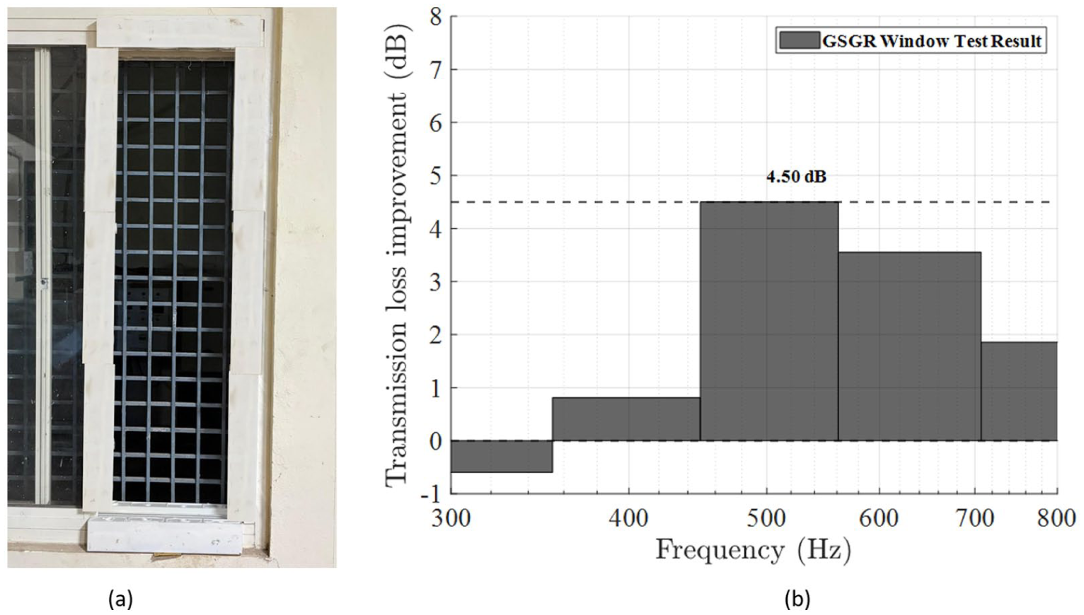
(a) Photograph of the GSGR resonator array retrofitted around an existing window opening for real-world validation, and (b) measured transmission loss improvement obtained for the installed configuration.
For consistency, the same omnidirectional sound source and microphones from the reverberation chamber experiments were employed here. The GSGR configuration was selected for the real-world validation experiment. The sound source was placed approximately 1.5 m from the window opening, at a central location relative to the window, while the source height was closer to the middle region of the opening.
Figure 14(b) shows the transmission loss improvement obtained for the GSGR configuration, resulting in a 4.5 dB reduction in a real-world scenario with a larger opening than that used in the reverberation chamber study. The results indicate that acoustic attenuation was retained even under a practical installation while maintaining a high effective ventilation area. This observation supports the feasibility of implementing the proposed perimeter-mounted resonator concept on larger window openings under the tested conditions.
Conclusions
The study investigates a resonator array setup that can be retrofitted to any existing windows of residential buildings. The study targets low-to-mid-frequency noise control while proposing a less invasive design, leading to a larger open ventilation area. The current study achieves this by keeping 70 % of the tested area open for ventilation, which is the largest opening studied. Four different configurations, with and without airflow, are tested in a twin reverberation chamber.
The effect of cavity volume has been examined, and the advantage of a larger resonator in ventilated acoustic treatment is observed, with larger units delivering significant attenuation across all configurations. Based on the experiments it can be concluded that the GSGR configuration works best for both no-flow and flow conditions with a marginal drop in TL improvement with flow.
From a practical design perspective, the present results suggest that larger resonator arrays are preferable when effective attenuation is required in the target frequency range. Although compact resonators allow more units to be accommodated within the frame, the experiments showed that their acoustic performance remained lower than that of the larger resonators. Therefore, for practical implementation, it is better to retain a sufficiently large resonator volume and tune the desired frequencies through parameters such as neck length, neck radius, and the number or combination of resonators in the array, rather than by making the resonators too compact.
The additional real-world validation further demonstrates the practical applicability of the proposed perimeter-mounted resonator concept while preserving effective ventilation pushing up to 96% open area. The array is designed to run along the window frame, allowing it to expand to accommodate large windows and providing more space for additional resonators. The design is also flexible, allowing for the targeting of different octave bands by tuning the individual frequencies of the resonators in the array, making it customizable for various applications. This also allows the design to be applied to ventilation paths in industrial equipment, enclosures, and HVAC openings by retrofitting the tuned array to the ventilation openings. The array can be manufactured from any sustainable materials, provided the resonator walls remain acoustically rigid.
The primary goal of the study was to propose a robust design that can be implemented on a large scale in residential buildings, where the proposed design can be retrofitted to any existing windows without compromising the primary objective of a window, which includes natural ventilation and an uninterrupted view. This finding offers a practical pathway for deployable ventilated acoustic treatment for urban settings.
Limitations and future work
The airflow analysis relied on a pedestal fan in a controlled environment. Although this gives an indication of how the resonator array performs under airflow, it may not fully replicate the complexity of natural wind behaviour. While the reverberation room testing was constrained by the opening size of the reverberation chamber, which is
Currently, an equal number of resonators is used to target each frequency. The study can be extended to determine the optimum number of resonators required per frequency for optimal performance. This can enable efficient use of the area.
In addition, future work will involve developing a weatherproof version of the arrays for long-term outdoor performance under varying environmental conditions. The non-invasive nature of the proposed design makes it suitable for integration into closed glass pane windows, further improving transmission loss at tuned frequencies. Realizing these goals in the future will transform the proposed design into a commercially viable product for ventilated acoustic treatment.
Footnotes

Funding
The authors received no financial support for the research, authorship, and/or publication of this article.
Declaration of conflicting interests
The authors declared no potential conflicts of interest with respect to the research, authorship, and/or publication of this article.