




Abstract
As a new type of structure, cable-stiffened single-layer latticed shell generally has an increased load-carrying capacity. In the past, greater emphasis was placed on analysing their stability behaviours using finite element method or approximate formulae. This work conducted experimental investigation into the stability behaviour of cable-stiffened single-layer latticed shells. Three experimental models, including one ordinary single-layer spherical latticed shell and two different types of cable-stiffened single-layer spherical latticed shells under three different types of load distributions, were investigated in this study. Corresponding numerical analyses were conducted to investigate the stability behaviour of the latticed shells as well. Both the experimental study and the numerical analyses indicate that the load-carrying capacity of single-layer latticed shell has been significantly improved by the introduction of the cable-stiffened system. The numerical results also show that the joint stiffness has remarkable effect on the stability of ordinary single-layer latticed shell, whereas the effect on corresponding cable-stiffened single-layer latticed shells is limited.
Keywords
Introduction
Cable-stiffened single-layer latticed shell (Schlaich and Schober, 1996, 1997) is a structural system that is reinforced by prestressed cable-stiffened system, such that its load-carrying capacity is increased. Ordinary single-layer latticed shells have a propensity to buckle primarily due to their characteristic of thin shell. To counter this, the cable-stiffened single-layer latticed shell is equipped with prestressed cable-stiffened system. This prestressed cable-stiffened system offers additional stiffness to the structure, which potentially provides a considerable improvement in the stability behaviour.
Practical applications of this type of structure can be found widely in the world since it was proposed. The first application (Alan, 1997) of the cable-stiffened single-layer latticed shell is the glass-grid dome of the Neckarsulm indoor swimming pool. The square grids of the Neckarsulm dome are changed to triangular grids by introducing diagonal prestressed cables, which results in considerable stiffness increase in the grids. Kumagaya dome (Umezawa et al., 2003) is another practical application of this type of structure, in which the grids are stiffened by both cables and posts. The posts are attached to the nodes of the Kumagaya dome, and the diagonal cables connect the ends of the posts and the nodes at the diagonal corners. More applications of this type of structure can be found in Schlaich and Schober (2002).
A number of research works have been conducted on the stability behaviour of cable-stiffened single-layer latticed shells. Schlaich (2004) explained the principle why the prestressed cables can be used to stiffen the quadrilateral grids. Feng et al. (2012, 2013) derived the approximate formulae to evaluate the linear buckling loads of cable-stiffened cylindrical and elliptic paraboloid latticed shells. Zhang and Fujimoto (2010) and Cai et al. (2012) investigate the stability behaviour of cable-stiffened single-layer lattice shells by finite element (FE) analyses. Wu et al. (2001) analysed the pretension introducing process of a kind of cable-stiffened lattice shell. Bulenda and Knippers (2001) discussed the importance to select proper imperfection distribution to capture the real load-carrying capacity. Li et al. (2014) analysed the parameters those affect the stability behaviour of cable-stiffened single-layer latticed shells. It must be noted that experimental studies of cable-stiffened single-layer have hitherto not been attempted in the previous works (Bulenda and Knippers, 2001; Cai et al., 2012; Feng et al., 2012, 2013; Li et al., 2014; Schlaich, 2004; Wu et al., 2001; Zhang and Fujimoto, 2010). The experimental investigation of this type of structure is therefore the main subject of this work.
For the single-layer latticed shells, the joints are generally designed to be rigid to provide sufficient stiffness to the grids. However, it is impossible to construct the joints to be fully rigid. Although research works on the effect of the joint stiffness have been conducted, most of them (Kato et al., 1998; López et al., 2006, 2007, 2011) aimed to investigate the effect of the joint stiffness on ordinary single-layer latticed shells. Thus, investigating the effect of joint stiffness on the stability behaviour of cable-stiffened single-layer latticed shell is another subject of this work.
In this work, experimental investigation, including one ordinary single-layer spherical latticed shell and two different types of cable-stiffened single-layer spherical latticed shells under three different types of load distributions, has been conducted. Numerical study into the stability behaviour of cable-stiffened single-layer spherical latticed shells has also been carried out. The results indicate that the stability behaviour of the cable-stiffened single-layer spherical latticed shells is far superior to corresponding ordinary spherical latticed shells. It has also been found that the stability behaviour of cable-stiffened single-layer spherical latticed shells is significantly affected by the cable-stiffened system. In other words, different layouts of the cable-stiffened systems contribute different increase in the load-carrying capacity and stiffness of the single-layer spherical latticed shell. In addition, the numerical study also shows that effect of the joint stiffness on the stability behaviour of cable-stiffened single-layer spherical latticed shells is negligible, although the effect on the ordinary single-layer spherical latticed shell is considerable.
Experimental program
Material testing
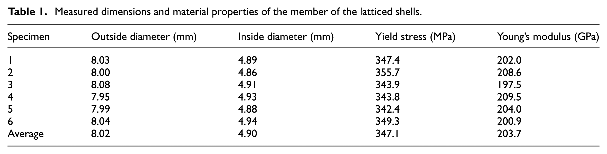
In order to obtain the material properties of the member of the latticed shells, material testing was conducted to determine the full tensile stress–strain response (Figure 1). Six tensile coupons, which were fabricated from Grade Q345 steel, were adopted to conduct the material testing. Strain gauges, which were used to capture the initial part of the stress–strain curve, were attached to both sides of the specimen. The extensometer was used to record the remaining part of the stress–strain curve, because the gauges could not capture the full stress–strain curve. The measured dimensions and material properties are presented in Table 1. As it can be seen, the average yield stress and Young’s modulus of the coupons are 347.1 MPa and 203.7 GPa, respectively, and these values are basically in accordance with the ones provided in the Chinese code for design of steel structures (GB 50017-2003, 2003).
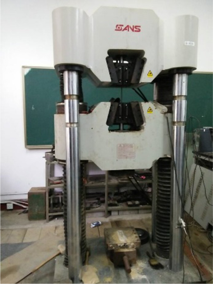
Photograph of material testing.
Measured dimensions and material properties of the member of the latticed shells.
Single-layer spherical latticed shell testing
As mentioned before, three experimental models, including one ordinary single-layer spherical latticed shell and two different types of cable-stiffened single-layer spherical latticed shells, were investigated in this study. The two cable-stiffened single-layer spherical latticed shells comprise the single-layer spherical latticed shell and two different types of cable-stiffened systems. This section aims to introduce the experimental program of the spherical latticed shells.
Ordinary single-layer spherical latticed shell
Figure 2 illustrates the model of ordinary single-layer spherical latticed shell, with a span and height of 2100 and 260 mm, respectively. The general length of the members of the spherical latticed shell is designed to be 460 mm. The members of the spherical latticed shell are fabricated from Grade Q345 steel circular hollow section with a design diameter and thickness of 8 and 1.5 mm; the material properties of the members are shown in Table 1.

Single-layer spherical latticed shell: (a) overall configuration of shell, (b) plan of shell and (c) elevation of shell.
Figure 3 is the photograph of spherical latticed shell. In this experiment, the single-layer spherical latticed shell is pin-supported on a ring beam. The pin-supported conditions were achieved about the circular direction through the provision of cylindrical joints. The members of the latticed shell were welded to the joints, which were designed to be cylinder. There is a hole in each joint, which is used to suspend the load. The section of the ring beam is designed to be box with a width and thickness of 120 and 8 mm, respectively, which is based on the principle that it should behave elastically and sufficiently rigid during the whole test process. The ring beam was welded to four circular sectional columns with a height of 550 mm in order to provide sufficient space for the loading process; the diameter and thickness of the columns are 102 and 6.5 mm, respectively.
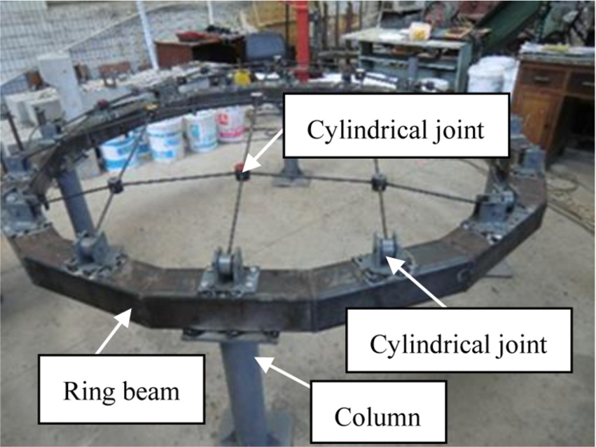
Photograph of ordinary spherical latticed shell.
Tensile testing of cable-stiffened system
As mentioned above, there are two types of cable-stiffened systems correspond to the two types of cable-stiffened single-layer latticed shells. Figure 4 illustrates the two types of cable-stiffened systems. In Layout I, diagonal cables are introduced into the grids of shell. In Layout II, both diagonal cables and posts are introduced into the grids of the shell. A post is attached to each joint of the grid and the diagonal cables connect the lower node of the post and the nodes at diagonal corners. Figure 5 is the photograph of the cable-stiffened systems, and the length of the post in Figure 5(b) is 120 mm. In this article, the cable-stiffened single-layer latticed shells with cable Layout I and Layout II are represented by ‘Shell I’ and ‘Shell II’, respectively. The corresponding single-layer latticed shell is represented by ‘Shell’. As depicted in Figure 6, the cables of the cable-stiffened systems comprise the following components: 1.2 mm cable, a steel turnbuckle that applied the pretension to the cable system and a strain gauge that adopted to measure the force in the cable.
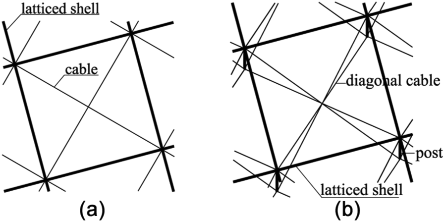
Two different types of layouts of the cable-stiffened systems: (a) Layout I and (b) Layout II.
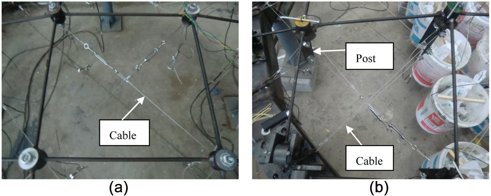
Photographs of the cable-stiffened systems: (a) Layout I and (b) Layout II.

Cable of the cable-stiffened systems.
Experimental process of spherical latticed shells
Loading plan
Three different load patterns, including concentrated load, half-span and full-span uniformly distributed load, were conducted for all the three experimental models. Iron sand was used to simulate the load. Figure 7 is the photograph of loading the ordinary latticed shell (Shell) under different types of load distributions; the buckets in the picture were used to hold the iron sand in the experiment. Note that the photographs of loading the cable-stiffened single-layer latticed shells are not exhibited in this article as they are similar to loading the ordinary one that shown in Figure 7. All the three models were loaded with the same procedure which would be stated in the following.
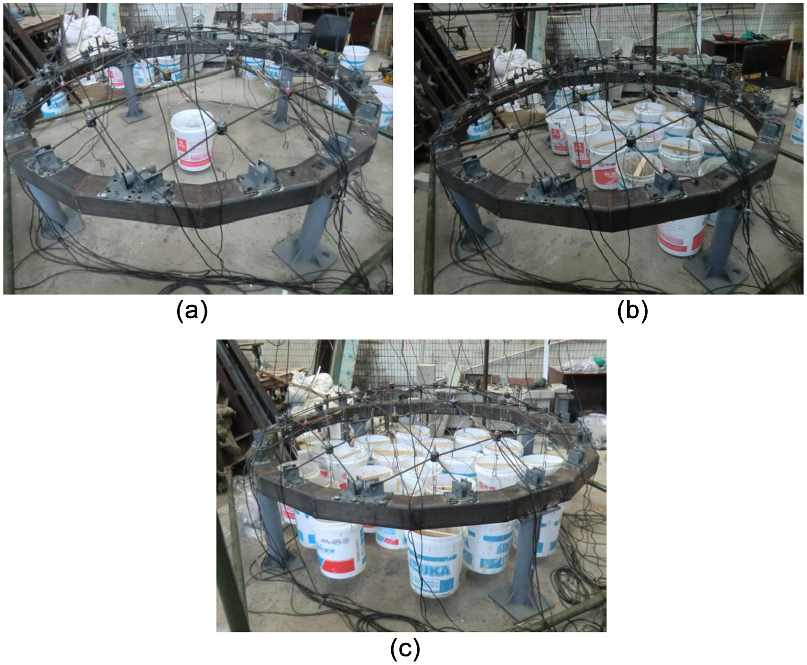
Photograph of ordinary spherical latticed shell under different load distributions: (a) concentrated load, (b) half-span uniformly distributed load and (c) full-span uniformly distributed load.
First, concentrated load was applied to the model gradually until it reached to the load limitation of 280 N; this load limitation was designed to ensure the material of the model kept in the range of elastic. Unloading the model after finishing the concentrated loading experiment and applying the half-span uniformly distributed load to the model with the same step, the load limitation of the half-span uniformly distributed load is 280 N as well. The full-span uniformly distributed load was applied to the model after unloading the half-span uniformly distributed load and kept loading the model until the instability occurred.
Arrangement of the measure points
In this experimental study, string displacement meters were adopted to record the vertical displacement of the nodes and the displacement measuring points are described in the following. Figure 8 shows the labelling convention of the displacement measuring points of the three latticed shells. For the concentrated load, the displacement of node 1 was measured. However, for the half-span and full-span uniformly distributed load, the displacements of nodes 1, 2, 3, 4 and 5 were recorded.
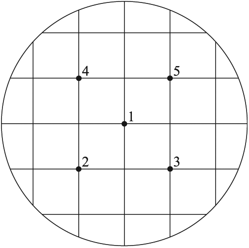
Displacement measuring points.
Experimental and numerical results
As mentioned above, the nodal displacements were recorded in the experiment. The experimental and numerical results of the nodal displacements under three different types of load distribution are presented in this section. The commercial code ANSYS was adopted to conduct the numerical analyses. The quadratic three-node beam element based on Timoshenko beam theory was adopted to simulate the members of the latticed shells and the posts. In contrast, three-dimensional (3D) uniaxial tension-only spar element was used to simulate the slack of the cables. The geometrical configuration and material properties of the numerical model were determined by the experimental measurement. It should be noted that the nodal displacement is defined as positive when the displacement direction is downward.
Displacement results
Concentrated load
Figure 9 illustrates the displacements of node 1 under concentrated load. As it can be seen, the maximum experimental displacement of Shell is around 5.3 mm; however, it decreases to around 4.8 and 2.5 mm, respectively, for Shell I and Shell II. This implies that the stiffness of the ordinary single-layer spherical latticed shell has been considerably enhanced by the cable-stiffened system.
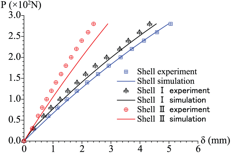
Displacements of measuring point No. 1 under concentrated load.
Half-span uniformly distributed load
Figure 10 indicates the displacements of measuring points No. 1–5 under half-span uniformly distributed load. Obviously, the maximum displacements of Shell I and Shell II are quite smaller than that of Shell, which implies that the stiffness of cable-stiffened single-layer latticed shells (Shell I and Shell II) is larger than that of ordinary latticed shell (Shell). Besides, it can be concluded that the cable Layout II (Figure 4(b)) is more effective on improving the structural stiffness than the cable Layout I (Figure 4(a)), because the maximum displacements of Shell II are smaller than those of Shell I.

Displacements of measuring points No. 1–5 under half-span uniformly distributed load: (a) No. 1, (b) No. 2, (c) No. 3, (d) No. 4 and (e) No. 5.
Full-span uniformly distributed load
Figure 11 demonstrates the relation between the nodal loads and displacements of the latticed shells under full-span uniformly distributed load. It can be seen that the load-carrying capacity of ordinary spherical latticed shell has been improved significantly by the cable-stiffened system. For the experimental results, the ultimate load applied to each node of the ordinary spherical latticed shell (Shell) is 300 N. However, it increases to 420 and 640 N for Shell I and Shell II, respectively. It can be also found that the load-carrying capacity of Shell II is much higher than that of Shell I; this implies that the cable layout shown in Figure 4(b) is more effective than the cable layout shown in Figure 4(a). For Shell I, only in-plane shear rigidity is strengthened by cable Layout I shown in Figure 4(a); in contrast, both in-plane shear rigidity and out-plane bending rigidity can be enhanced by cable Layout II shown in Figure 4(b). Thus, the load-carrying capacity of Shell II is higher than that of Shell I, although both of them are higher than that of Shell. It should be noted that all the measuring point displacements of Shell II are negative; this is because the instability modes of Shell II which would be presented later.
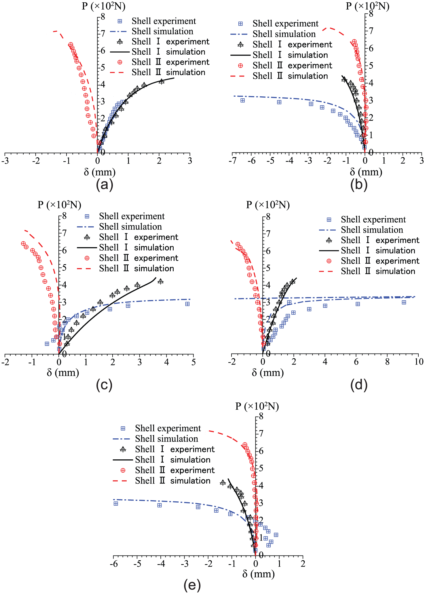
Displacements of measuring points No. 1–5 under full-span uniformly distributed load: (a) No. 1, (b) No. 2, (c) No. 3, (d) No. 4 and (e) No. 5.
Instability modes
Figure 12 illustrates the instability modes of different spherical latticed shells under full-span uniformly distributed load. As it can be seen, the instability modes of Shell and Shell I are global instability, whereas the instability mode of Shell II is local instability. A possible reason for Shell II exhibits local instability is that the initial pretension in cables is higher or the initial bending of the members of the latticed shell is non-negligible.
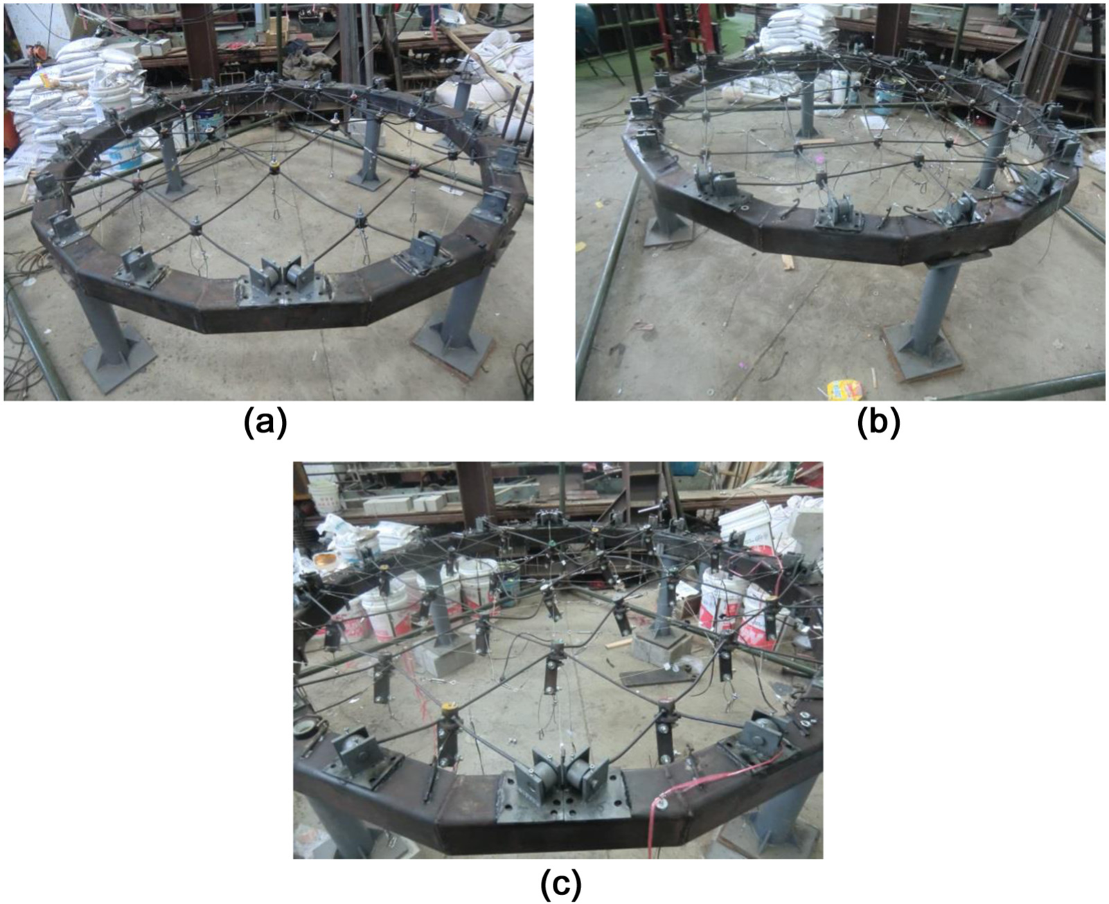
Instability modes of spherical latticed shells under full-span uniformly distributed load: (a) Shell, (b) Shell I and (c) Shell II.
Numerical analyses
The above experimental investigation compared the stability behaviour between ordinary spherical latticed shells and cable-stiffened ones. This section aims to compare their stability behaviours according to numerical analyses. In the experimental study, only two types of cable layouts (Figure 4) were introduced to the ordinary latticed shell. To enlarge the scope of the cable-stiffened latticed shells, another new type of cable-stiffened single-layer spherical latticed shell with cable Layout III (See Figure 13) is analysed as well in this section. In the Layout III, the post is placed in the middle of the grid, and the upper and lower nodes of the post are connected to the joints of the grids by diagonal cables. In addition, the parallel cables are placed in two directions through the upper and lower nodes of the post of all the grids. For convenience, the cable-stiffened single-layer spherical latticed shell corresponds to cable Layout III is named as ‘Shell III’ in this article. The effect of three types of joints, including rigid joint, semi-rigid joint and scissor-type joint, on the stability behaviour of different spherical latticed shells is also investigated in these numerical analyses.
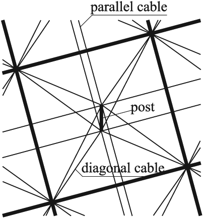
Layout III of the cable-stiffened systems.
Numerical model and methodology
Analytical model of the spherical latticed shell
Figure 14 illustrates the configuration of the spherical latticed shell, the span of the latticed shell is 80 m and the length of the members of the latticed shell is 4 m. The latticed shell is pin-supported on its circular boundary. Uniformly distributed load is applied at each node of the shell. Tubular sections are adopted for all the members of the latticed shell; the outer diameter and thicknesses of the members are 351 and 10 mm, respectively.
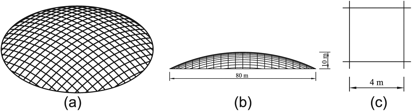
Ordinary spherical latticed shell: (a) overall configuration of shell, (b) elevation of shell and (c) grid of shell.
As mentioned earlier, three different types of cable-stiffened single-layer spherical latticed shells (Shell I, Shell II and Shell III) and corresponding ordinary one (Shell) are analysed in this section. In this study, the cross-sectional area of the cables and the pretension in cables are 261.54 mm2 and 300 MPa, respectively. The lengths of the posts in Layout II and Layout III are 1000 and 2000 mm, respectively, and the cross-sectional area is 2121 mm2.
The material of the posts and all the members is Q345 steel with a yielding stress of 345 MPa. The corresponding Young’s modulus and Poisson’s ratio are 206 GPa and 0.3, respectively. The steel is assumed to be an ideal elastic–plastic material in this study. The material of the cables is steel spiral strand rope with a Young’s modulus of 160 GPa. The cables are treated as elastic in the analysis. The commercial code ANSYS is used to conduct these numerical analyses, and the same element types with those in section ‘Experimental and numerical results’ are adopted.
Analytical model of the semi-rigid joint
As shown in Figure 15, the joints of the grids can be taken as tubular X-joints, in which the brace members are welded onto the surfaces of the chord members. Thus, the joints should be taken as semi-rigid in accurate analysis due to the deformation of the surface of the joints.
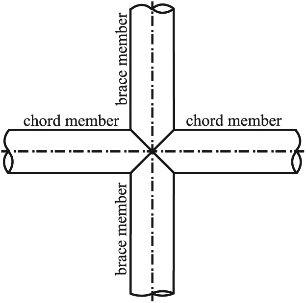
Tubular X-joint.
In this study, the in-plane and out-of-plane rotational stiffness of the joints were treated as semi-rigid and the corresponding moment–rotation relationships shown in Figure 16 are adopted to simulate the semi-rigid behaviour of the joints. In Figure 16,

Curve of bending moment to rotation of unstiffened tubular joint: (a) in-plane moment–rotation curve and (b) out-plane moment–rotation curve.
Analytical model of the scissor-type joint
Scissor-type joint is a type of rotatable joint, which is convenient to construct. As shown in Figure 17, the members are connected by the pin at the intersection in scissor-type joint. Obviously, the members can rotate freely in-plane; this characteristic decreases the stiffness of the quadrilateral grid in latticed shells. However, the introduction of the cables in the grids can increase the stiffness of the quadrilateral grids; this effect can offset the decrease in the grid stiffness due to the adoption of scissor-type joint to some extent. Thus, it is essential to investigate and compare the effect of scissor-type joint on the stability behaviour of different types of latticed shells, which is part of the work in this study. In the numerical analyses, the combin7 element in ANSYS was adopted to simulate the scissor-type joint.

Detail of the scissor-type joint.
Analytical methodology
The numerical analyses in this section comprise linear and nonlinear buckling analyses. The linear buckling analysis, which is based on the original configuration of the structure, can be used to obtain the linear buckling loads and modes. However, the real load-carrying capacity of the structure is lower than the linear buckling load due to the imperfection and the nonlinear behaviour. Thus, the results of linear buckling analyses would not be presented in this section, although they have been conducted. For the nonlinear buckling analyses, both geometric nonlinearity and material nonlinearity were considered in this study.
As for the geometrical imperfection distribution, most of the previous research works (Fan et al., 2010; Yamashita and Kato, 2001) adopted the lowest linear buckling mode to be the geometrical imperfection distribution. However, recent research (Jiang et al., 2013) shows that the imperfection distribution follows the lowest linear buckling mode does not always correspond to the real load-carrying capacity. Thus, the following method is adopted to determine the geometrical imperfection distribution in the nonlinear analyses: The first five linear buckling modes obtained from linear buckling analysis were adopted to introduce the imperfection distribution in the nonlinear analyses separately, and the one corresponds to the lowest buckling load (real load-carrying capacity) is treated as the geometrical imperfection distribution. In accordance with the Chinese technical specification for space frame structures (JGJ7-2010, 2010), the magnitude of geometrical imperfection was selected to be L/300 (L is the span of the spherical latticed shell) in the nonlinear analyses.
Numerical results
Figure 18 illustrates the equilibrium paths represented by the load P versus the maximum nodal displacement with the joint types varying. It must be noted that the displacement depicted in the equilibrium paths in this article is the maximum node deflection of the latticed shell when the instability occurs. Obviously, the load-carrying capacity and structural stiffness of the ordinary spherical latticed shell have been considerably improved by the cable-stiffened systems. It can also be found that the stability behaviour of ordinary spherical latticed shell is affected by the joint stiffness significantly, especially when the joints are scissor-type joints. However, the effects of joint stiffness on the load-carrying capacities of cable-stiffened single-layer spherical latticed shells are negligible.

Equilibrium paths with different joint types: (a) Shell, (b) Shell I, (c) Shell II and (d) Shell III.
Table 2 shows the load-carrying capacities of the shells; the coefficient k is defined as the ratio of the load-carrying capacity of cable-stiffened latticed shells to the ordinary one. For the rigid joints, the value of k varies from 1.55 to 2.13 with the types of shells changed from Shell I to Shell III. However, this value varies from 2.34 to 3.25 with the types of shells changed from Shell I to Shell III when the joint type is scissor-type joints. Thus, the introduction of the cable-stiffened system makes it possible to adopt scissor-type joints in practical engineering.
Load-carrying capacities of shells.

Concluding remarks
This work studied the behaviour of cable-stiffened single-layer spherical latticed shells according to experimental and numerical investigations. Three different spherical latticed shells, including one ordinary and two cable-stiffened spherical latticed shells, were tested in this study. The conclusions of this study can be summarised as follows:
The experimental investigation has indicated that both the stiffness and load-carrying capacity of ordinary single-layer latticed spherical shell can be considerably enhanced by the cable-stiffened systems. Thus, the cable-stiffened single-layer spherical latticed shells deserve wider applications in practice due to their superior stability behaviour.
It has also been demonstrated that the stability behaviour of cable-stiffened spherical latticed shells is significantly affected by the layouts of the cable-stiffened systems. For the three types of cable layouts discussed in this article, Layout II and Layout III are more effective than Layout I in improving the stability behaviour of the structure. Because both shear stiffness in-plane and bending stiffness out-plane of the grids can be enhanced by cable layouts II and III, whereas only shear stiffness in-plane is enhanced by cable Layout I.
The load-carrying capacity of ordinary single-layer spherical latticed shell is affected significantly by the joint stiffness, especially when the joint is scissor-type joint. However, the effect of joint stiffness on the load-carrying capacity of cable-stiffened spherical latticed shells is negligible, even if the joint is scissor-type joint. This characteristic makes it possible to adopt scissor-type joint when designing cable-stiffened single-layer spherical latticed shells.
Footnotes
Declaration of Conflicting Interests
The author(s) declared no potential conflicts of interest with respect to the research, authorship and/or publication of this article.
Funding
The author(s) disclosed receipt of the following financial support for the research, authorship and/or publication of this article: This work was funded by the National Natural Science Foundation of China (project no. 51178331).