
Abstract
LiteSteel beam is a hollow flange channel made from cold-formed steel using a patented manufacturing process involving simultaneous cold-forming and dual electric resistance welding. LiteSteel beams are currently used as floor joists and bearers in buildings. However, there are no appropriate design standards available due to their unique hollow flange geometry, residual stress characteristics and initial geometric imperfections arising from manufacturing processes. Recent research studies have focused on investigating the structural behaviour of LiteSteel beams under pure bending, predominant shear and combined actions. However, web crippling behaviour and strengths of LiteSteel beams still need to be examined. Therefore, an experimental study was undertaken to investigate the web crippling behaviour and strengths of LiteSteel beams under end-one-flange and interior-one-flange load cases. A total of 23 web crippling tests were performed and the results were compared with the current AS/NZS 4600 and AISI S100 design standards, which showed that the cold-formed steel design rules predicted the web crippling capacity of LiteSteel beam sections very conservatively under end-one-flange and interior-one-flange load cases. Therefore, suitably improved design equations were proposed to determine the web crippling capacity of LiteSteel beams based on experimental results. In addition, new design equations were also developed under the direct strength method format. This article presents the details of this experimental study on the web crippling behaviour and strengths of LiteSteel beams under end-one-flange and interior-one-flange load cases and the results.
Keywords
Introduction
Cold-formed steel sections are most commonly used in recently constructed low-rise residential, industrial and commercial buildings, mainly due to their thinner and lightweight characteristics. They are made of thin high strength cold-formed steels in various shapes and geometries to suit the requirements of higher moment capacities. The most commonly used cold-formed steel sections are channel and lipped channel sections. Recently, a new cold-formed steel hollow flange channel section known as LiteSteel beam (LSB) is produced from a single strip of high strength steel using a combined cold-forming and dual electric resistance welding process (Figure 1). The nominal sizes of LSB sections are provided in Table 1. LSB exhibits effective distribution of steel with two torsionally rigid rectangular hollow flanges, which provide very good moment capacity to the thin and lightweight section. Therefore, they can be used as floor joists and bearers in low-rise buildings (OneSteel Australian Tube Mills (OATM), 2008).

Hollow flange channel sections (OATM, 2008).
Nominal dimensions of LSB sections (OATM, 2008).

LSB: LiteSteel beam.
d, bf, df = external dimensions.
Corner radii ro = 2tf mm, ri = 3.0 mm; flange depth df = bf/3.
LSBs are manufactured from cold-formed steel with a yield strength of 380 MPa and a tensile strength of 490 MPa. The nominal yield strength of the hollow flanges considerably increased to 450 MPa compared to 380 MPa of web during the cold-forming processes. In addition to the increased nominal yield strength, residual stresses and initial geometric imperfections are also introduced during the unique manufacturing process of LSBs. These characteristics make the LSB a unique cold-formed steel section, different from conventional open cold-formed steel sections such as the lipped channel sections. Therefore, currently available design standards are not directly applicable to the LSBs.
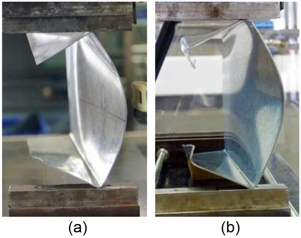
Bearing failure can be categorised into web crippling (or web bearing) and flange crushing depending on the failure location in the sections. LSBs are commonly used as floor joists and bearers in recently constructed low-rise buildings. However, they are vulnerable to web crippling failures (or web bearing), which are local failures that occur at points of transverse concentrated loading or at the supports (Figures 2 and 3). Theoretical web bearing strength prediction of cold-formed steel beams involves various complex factors such as local yielding in the loading region and instability of the web element. Therefore, past research studies have adopted empirical design methods developed from experimental studies to predict the cold-formed steel beam’s web bearing strength. These empirical design rules stipulated in the current design standards were based on more than 1200 tests of conventional cold-formed steel sections such as C-, Z- and hat and built-up sections undertaken since 1940s (Khan and Walker, 1972; Macdonald et al., 2011; Prabakaran, 1993; Uzzaman et al., 2013; Walker, 1975; Winter and Pian, 1946; Young and Hancock, 1998, 2001) for the four types of web bearing loading conditions (IOF: interior-one-flange; EOF: end-one-flange; ITF: interior-two-flange; ETF: end-two-flange) shown in Figure 4. Recent research studies (since 2005) have focused on developing unified web bearing capacity equations for the most commonly used cold-formed steel sections. These equations define the parameters influencing the web bearing capacity using particular web crippling coefficients. These coefficients are namely clear web height to thickness ratio (d1/tw), inside bent radius to thickness ratio (ri/tw) and bearing length to thickness ratio (lb/tw). However, these capacity equations for web bearing are not appropriate to the LSB sections due to the presence of rectangular flanges instead of the plate element flanges that exist in most commonly used cold-formed steel sections.
Web crippling failures of conventional cold-formed steel sections: (a) unlipped channel and (b) lipped channel.

Web crippling failures of LSBs.
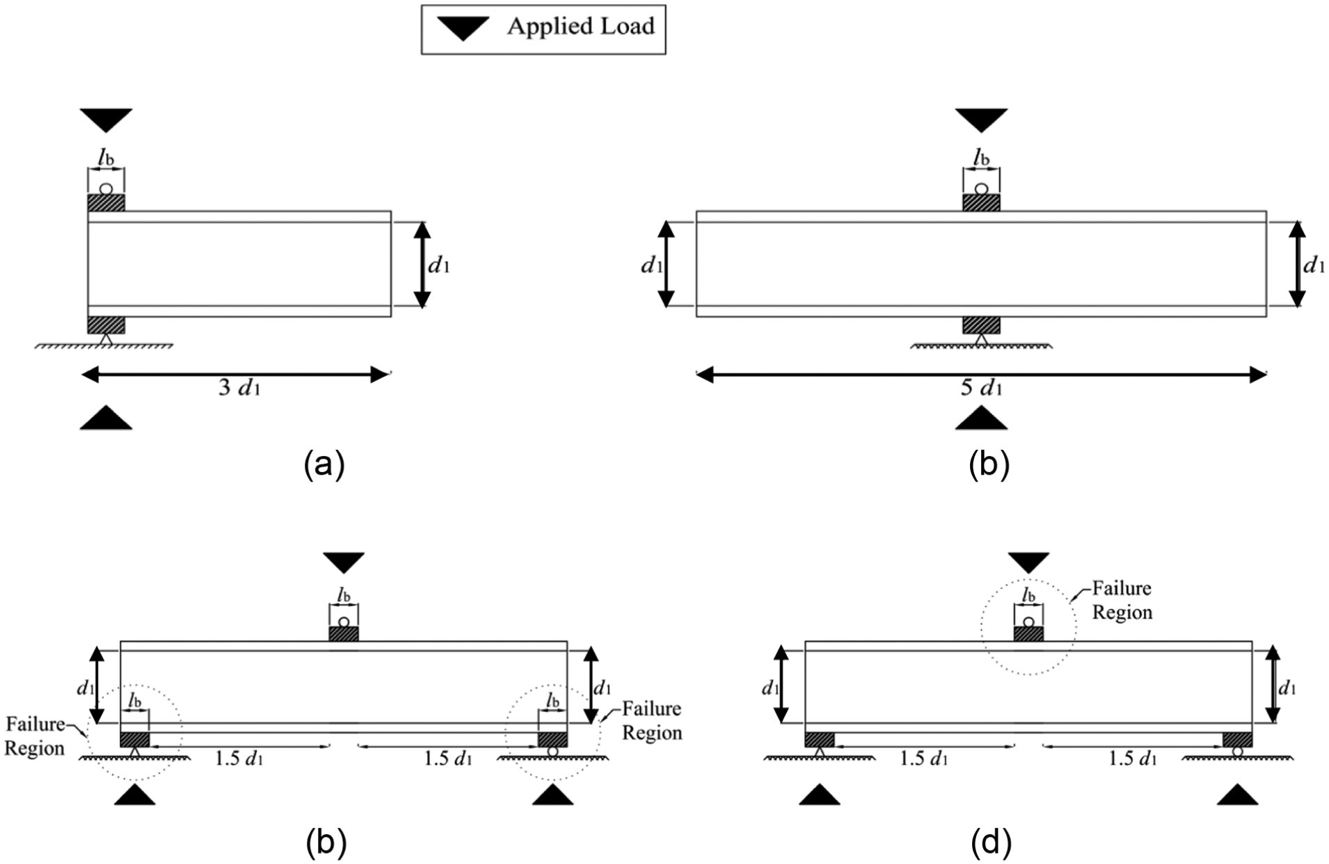
Loading conditions for web crippling tests (American Iron and Steel Institute (AISI), 2008): (a) end-two-flange (ETF) loading, (b) interior-two-flange (ITF) loading, (c) end-one-flange (EOF) loading and (d) interior-one-flange (IOF) loading.
The web crippling behaviour of LSB steel sections differs from conventional cold-formed steel sections due to their torsionally rigid rectangular hollow flanges and the unique welded web–flange connections, which provide enhanced rotational restraint to the web. Keerthan and Mahendran (2010a, 2011) have considered the enhanced rotational restraint at the LSB web–flange connection in the existing shear capacity design rules. However, the effect of enhanced rotational restraint has not been considered yet in the web crippling capacity of LSB.
The flexural, shear and web crippling capacities need to be evaluated when LSBs are used in floor joists and bearers. Recent research studies have investigated the flexural (Anapayan et al., 2011; Anapayan and Mahendran, 2012a, 2012b) and shear (Keerthan et al., 2013; Keerthan and Mahendran, 2010a, 2010b, 2011, 2013) behaviour and capacities of LSBs. However, limited research has been performed on the web crippling behaviour and strength of LSB sections. Recently, Keerthan et al. (2014) completed an experimental study of the web crippling behaviour of LSB sections under ETF and ITF load cases. In this research, the web crippling behaviour and strength of LSBs under EOF and IOF load cases are investigated using experimental studies.
This research article presents the details of the experimental studies on LSBs under EOF and IOF load cases to investigate their web crippling behaviour and strength. The web crippling capacities from the experimental studies were compared with the web crippling capacities predicted using AS/NZS 4600 (Standards Australia/Standards New Zealand (SA), 2005) and AISI S100 (AISI, 2012) design standards. The design rules predicted the web crippling capacities of the LSBs conservatively; thus, new design equations were proposed to predict the web crippling capacities of LSBs. In addition, appropriate design rules under direct strength method (DSM) were also developed.
Previous web crippling studies
General
The web crippling failure mode is important in the design of cold-formed steel beam sections when used as floor joists or bearers. The web crippling effect was initially considered in the design specifications published by American Iron and Steel Institute in 1940. Winter and Pian (1946) initiated the research and development in web crippling, which was followed by various research studies performed by Winter and Pian (1946), Khan and Walker (1972), Walker (1975), Prabakaran (1993), Young and Hancock (2001), Macdonald et al. (2011) and Uzzaman et al. (2013). These research studies yielded different design rules for predicting web crippling capacities for various cold-formed steel beam sections. In the early stages, the American Specification (AISI, 1996) considered dissimilar design rules for different types of cross-sections and load cases. However, the currently available design rule uses a unified web crippling capacity equation (equation (1)), which is applicable to different types of section geometry and load cases (ETF, ITF, EOF and IOF). This web crippling design equation provided in AS/NZS 4600 (SA, 2005) and AISI S100 (AISI, 2012) design standards was developed based on various experimental studies performed throughout the world. In comparison to ETF and ITF load cases, limited web crippling tests have been undertaken under EOF and IOF load cases.
Web crippling test method
The web crippling capacities of a beam can depend on its overall specimen length. The recently introduced AISI S909 recommends the following specimen lengths for web crippling tests under four loading cases illustrated in Figure 4


where d1 is the depth of the flat portion of the web measured along the plane of the web.
The AISI S909 recommends the use of toe-to-toe or back-to-back, but separated beam sections while performing the web crippling tests to eliminate the effect of torsion. The schematic diagram and representative cross-section of toe-to-toe but separated standard test specimen under EOF and IOF load cases are shown in Figure 5. As per the AISI S909 test methods, the tests should be performed under the following loading and restraint conditions for both EOF and IOF load cases:
The load is applied to the flanges at mid-span.
The ends bear on the supports.
A 20 × 20 × 3.0 Equal Angle (EA) is fastened to the top flanges (and the bottom flanges if desired) to interconnect the two sections at ¼ and ¾ points along the span.
The webs of the specimens may be stiffened at the load point.
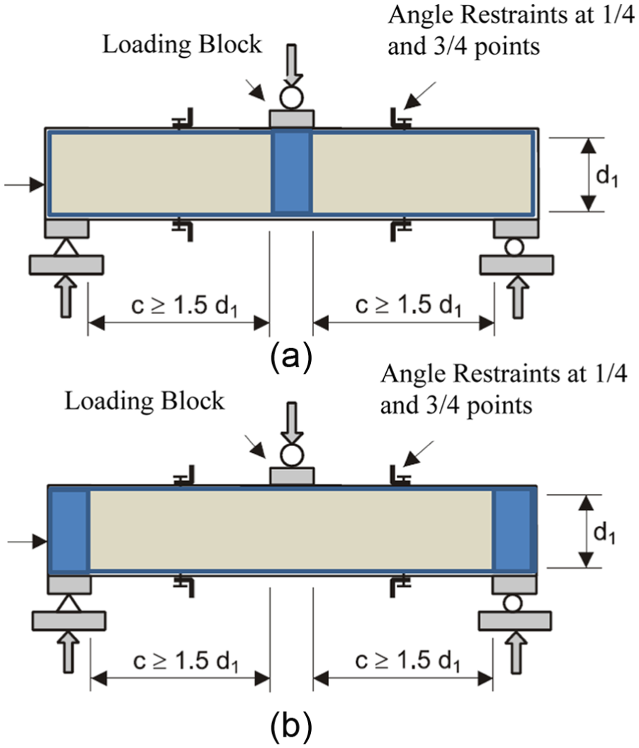
AISI S909 test method (AISI, 2008): (a) EOF load case and (b) IOF load case.
AS/NZS 4600 and AISI S100 design equations
The design of cold-formed steel members is performed using AS/NZS 4600 (SA, 2005) in Australia and New Zealand. The design guidelines for web crippling capacity (Rb) provided in AS/NZS 4600 (SA, 2005) are only applicable to open cold-formed steel sections. The parameters considered in the standard web crippling capacity design rules are clear height to thickness ratio (d1/tw), inside bent radius to thickness ratio (ri/tw), bearing length to thickness ratio (lb/tw), yield stress (fy) and web thickness (tw). These design rules provided in AS/NZS 4600 for web crippling capacity were developed based on Prabakaran’s (1993) experimental and statistical studies on various cold-formed steel sections. Based on the results from more than 1200 web crippling experiments, a unified design equation for open cold-formed steel sections was proposed using four web crippling coefficients given in equation (1). These web crippling coefficients for the selected support and flange conditions and various load cases are given in Table 2. This equation was also included in the North American specification for the design of cold-formed steel structural members (AISI, 2012)
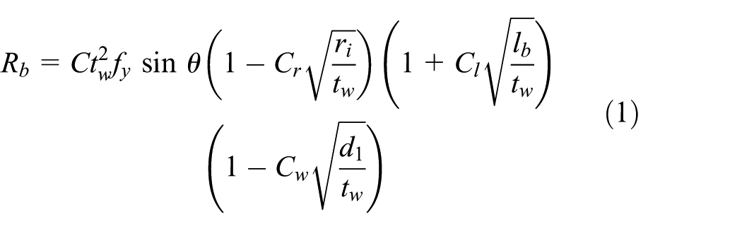
where C is the coefficient, θ is the angle between the plane of the web and the plane of the bearing surface 45° ≤ θ ≤ 90°, Cr is the coefficient of inside bent radius, Cl is the coefficient of bearing length and Cw is the coefficient of web slenderness.
Web crippling coefficients in equation (1) (AS/NZS 4600).
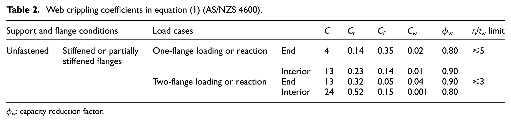
ϕw: capacity reduction factor.
Past research
An experimental investigation was carried out by Young and Hancock (2001) to investigate the behaviour of cold-formed unlipped DuraGal channels subjected to web crippling under all four loading conditions (EOF, IOF, ETF and ITF). Figure 6 shows the test set-up used by Young and Hancock (2001) for IOF load case. Based on the results of their research, the design web crippling strength predictions given by the old American standard (AISI, 1996) was found to be unconservative for the unlipped channel sections tested. In their article, a simple plastic mechanism expression for web crippling strength of unlipped channels is also proposed.

Test set-up for IOF load case (Young and Hancock, 2001): (a) front view and (b) end view.
Recently, Macdonald et al. (2011) conducted experimental and numerical studies to investigate the web crippling behaviour of lipped channel beams (LCBs) under ETF, ITF, EOF and IOF load cases. Figure 7 shows the test set-up used in Macdonald et al.’s (2011) tests. They found that the bearing length, corner radii and clear height of web had an effect on the web crippling strength of LCBs, particularly for EOF and IOF load cases. Uzzaman et al. (2013) conducted experimental and numerical studies to investigate the effect of offset web holes on the web crippling strength of cold-formed steel LCBs under ETF and ITF load cases. They also did web crippling tests of LCBs without web openings under the same load cases.

Test set-up for EOF and IOF load cases (Macdonald et al., 2011): (a) EOF load case and (b) IOF load case.
Young and Hancock (2001) also developed design equations to predict the web crippling capacities of channels with stocky webs based on their test results. These equations were derived using a combination of theoretical and empirical analyses. It was assumed that the bearing load is applied eccentrically to the web due to the presence of the corner radii, which produces bending of the web out of its plane. This will lead to a plastic mechanism as shown in Figures 8 and 9

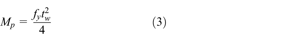


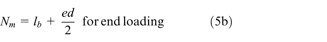
where Ppm is the web crippling strength; Mp is the plastic moment per unit length; r and ri are the centreline and inside corner radii, respectively; d1 is the depth of the flat portion of the web; d is the overall depth of the web; tw is the thickness of the web; fy is the yield stress; lb is the bearing length; Nm is the assumed mechanism length; Ca = 1.44 and Cb = 0.0133.

Mechanism model proposed by Young and Hancock (2001): (a) one-flange loading and (b) two-flange loading.
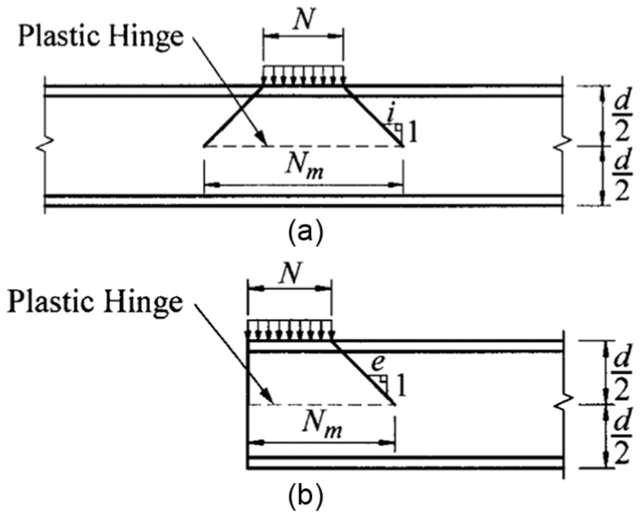
Plastic hinge position and mechanism length (Nm) (Young and Hancock, 2001): (a) interior loading and (b) end loading.
The correction factors for interior loading are i = 1.3 and 1.4 for IOF and ITF load cases, respectively, and the correction factors for end loading are e = 1.0 and 0.6 for EOF and ETF load cases, respectively. The elastic buckling and potential post-buckling strengths of cold-formed steel beam web panels need to be accurately determined in order to predict their actual web crippling capacities. In this regard, the support condition of the web–flange juncture is vital in computing the web crippling capacities. In a recent article, Choy et al. (2014) assumed simply supported boundary conditions at the web–flange juncture for LCBs. Keerthan and Mahendran (2010a, 2011) considered enhanced restraint at the web–flange juncture as provided by the hollow flanges of a LSB section to compute its shear capacity. However, the effect of enhanced restraint provided by the hollow flanges of LSB has never been investigated for web crippling.
Web crippling tests of LSBs under EOF and IOF load cases
In this research, a series of 23 web crippling tests was carried out under EOF and IOF load cases on four different LSB sections. The experimental programme including test set-up and test specimen sizes was developed based on AISI S909 (AISI, 2008) standard test procedures. As this experimental study was mainly on web crippling behaviour, the specimens were deemed to fail under web crippling prior to reaching other failure modes such as bending and shear failures.
Test specimens, test set-up and test procedure
The test set-up comprises of four different LSB sections with 150 × 45 × 1.6 LSB, 150 × 45 × 2.0 LSB, 200 × 45 × 1.6 LSB and 200 × 60 × 2.5 LSB, which were assembled in toe-to-toe configuration as shown in Figure 10. These are the most commonly used LSB sections in the building industry. The details of 23 web crippling test specimens are listed in Table 3, which includes the bearing length, load case, measured web thicknesses (tw), clear web heights (d1) and yield stresses (fyw) of the web elements of tested LSBs. The nominal inside bent radius (ri) of LSBs is 3 mm; however, it was considered as zero in the web crippling capacity calculations, because the outside corners are filled with weld material unlike the rounded corners in standard cold-formed channel sections. The specimen lengths were selected based on the AISI S909 standard web crippling test procedure (AISI, 2008), in which the specimen length should be at least equal to three times the clear web height plus three times the bearing plate length for EOF and IOF load cases (Figures 4 and 5).
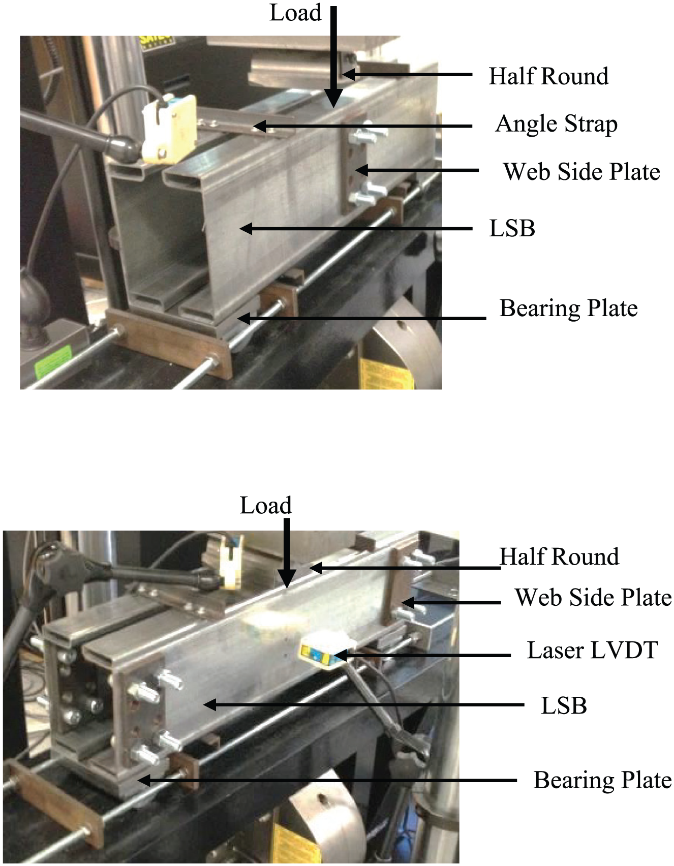
Experimental set-up: (a) EOF load case and (b) IOF load case.
Details of test specimens.

LSB: LiteSteel beam; EOF: end-one-flange; IOF: interior-one-flange.
ri = 3 mm.
The web crippling tests were performed using an Instron testing machine. The testing conditions were varied by choosing three different bearing plate sizes of 50, 100 and 150 mm for both EOF and IOF load cases. The boundary conditions were pinned at the supports to ensure simply supported beam end conditions. The data acquisition system was setup to measure the applied load and the test beam displacements at two different locations. The vertical and lateral displacements were measured using two laser displacement transducers, which were located on the test beam near the loading point and at the middle of the web panel, respectively, as shown in Figure 10. A small initial load was applied to the specimen before starting the tests in order to allow the loading and support systems to make good contact on the bearings. After that, the data acquisition system was initialised with zero values. Finally, the specimens were subjected to loading at a rate of 0.7 mm/min using the loading cross-head.
Test results and analyses
This section presents the experimental results and analyses of the web crippling tests on LSBs under EOF and IOF load cases. These test results are important to understand the actual web crippling behaviour of LSB sections as well as to provide sufficient data for developing web crippling capacity design rules applicable for LSB sections under EOF and IOF load cases. Table 4 summarises the web crippling capacities from the experimental studies.
Comparison of web crippling capacities of LSBs with currently available design rules.

LSB: LiteSteel beam; COV: coefficient of variation; EOF: end-one-flange; IOF: interior-one-flange.
Test specimens 14–16 failed in combined flange crushing and web crippling.
Figure 11(a) to (c) shows the web crippling failure modes of 200 × 45 × 1.6 LSBs (EOF load case) with 50, 100 and 150 mm bearing lengths, respectively, while Figure 12(a) and (b) shows the web crippling failure modes of 150 × 45 × 2.0 LSBs (IOF load case) with 100 and 150 bearing lengths, respectively.
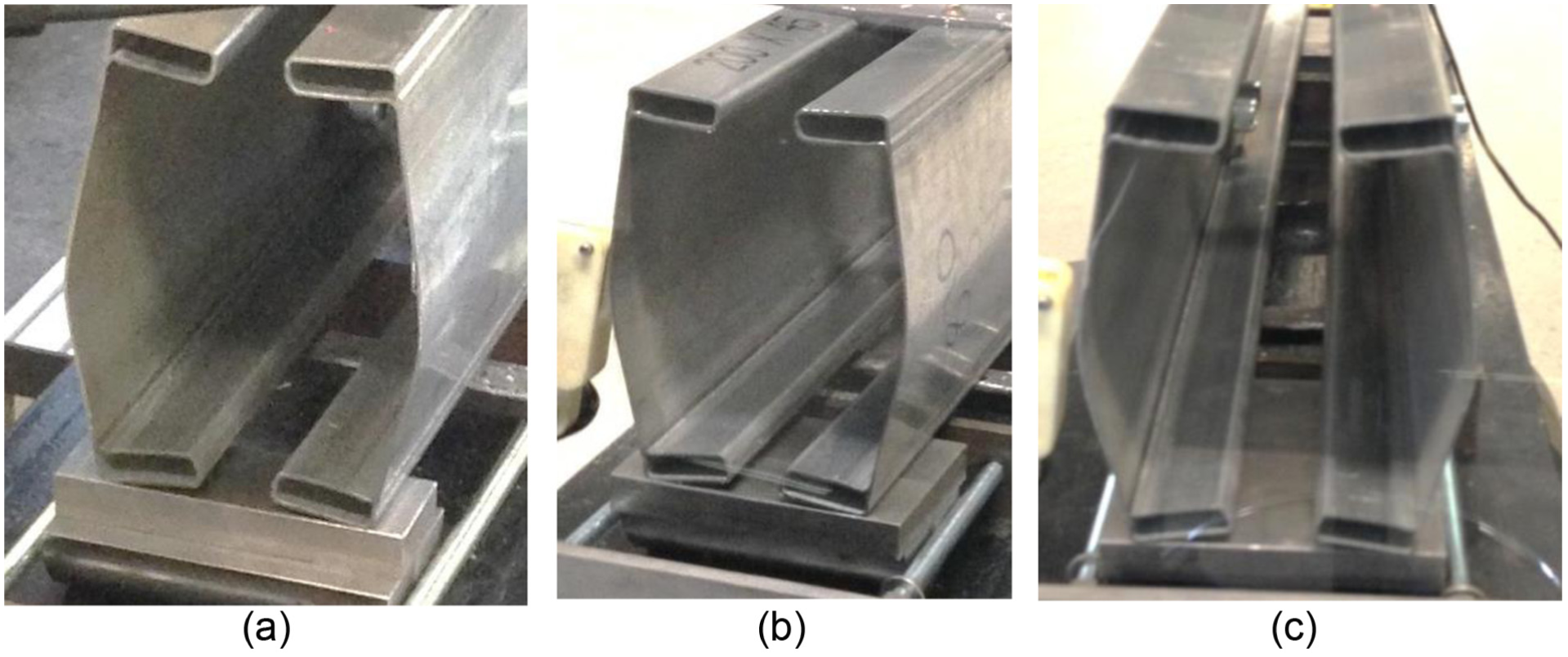
Web crippling failure modes of 200 × 45 × 1.6 LSBs under EOF load case: (a) bearing length = 50 mm, (b) bearing length = 100 mm and (c) bearing length = 150 mm.
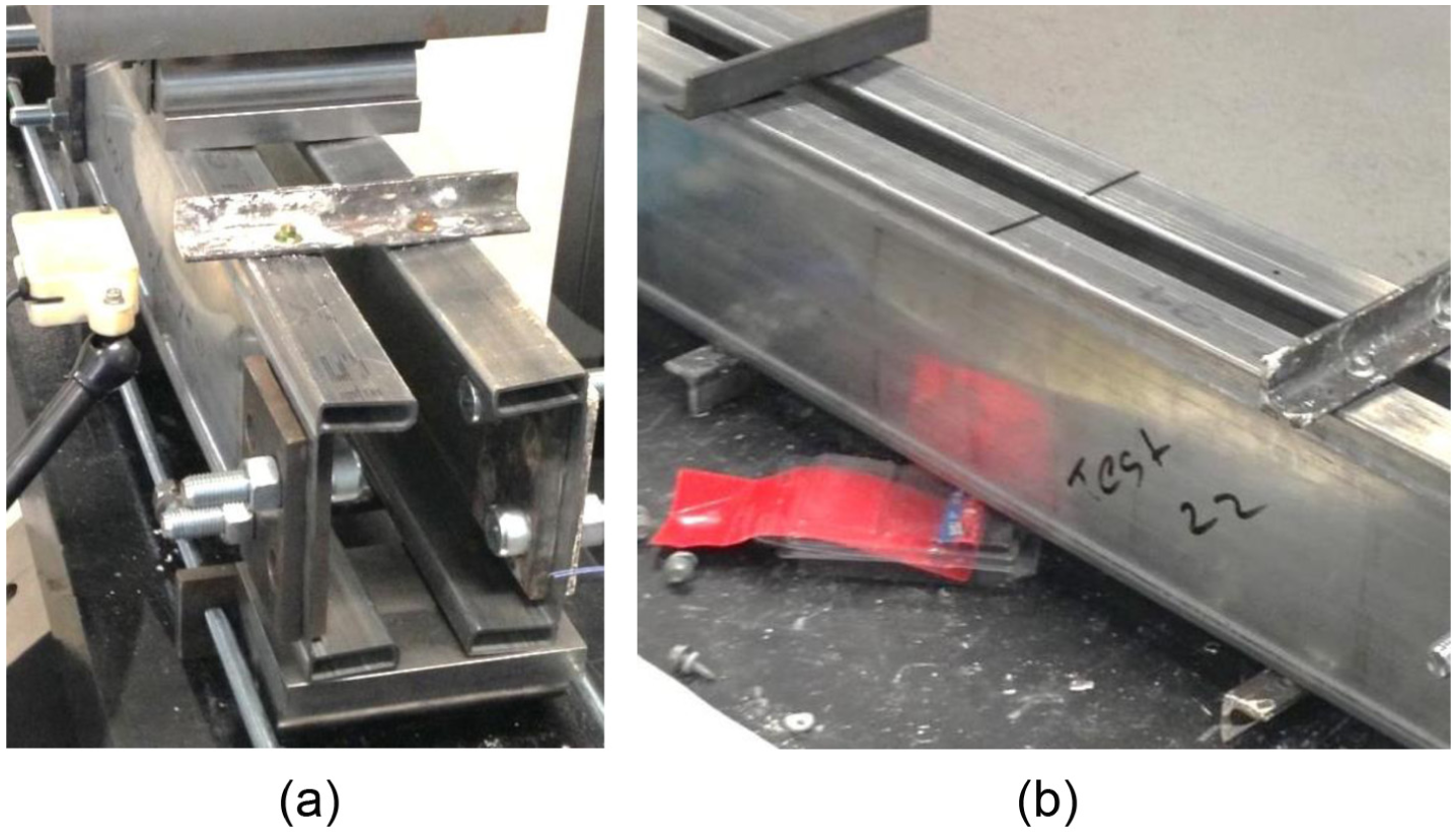
Web crippling failure modes of 150 × 45 × 2.0 LSBs under IOF load case: (a) bearing length = 100 mm and (b) bearing length = 150 mm.
Web crippling failure mode was observed in most of the test specimens, while test specimens with smaller bearing length (50 mm) failed in combined flange crushing and web crippling. Figure 13(a) to (c) shows the failure modes of combined flange crushing and web crippling of LSBs in test specimens 14–16. As this research study was mainly focused on web crippling failure, investigation of combined flange crushing and web crippling was not considered (see tests specimens 14–16). The load–deflection curves obtained from the web crippling tests of 200 × 45 × 1.6 LSB section with 100 mm bearing plate are shown in Figure 14(a) and (b) for EOF and IOF load cases, respectively. These load–deflection curves can be used to validate the finite element models.
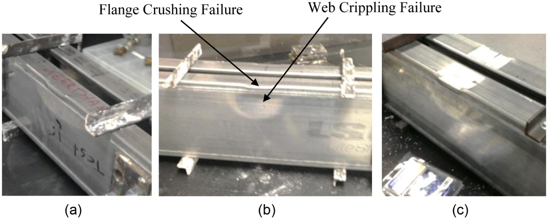
Flange crushing and web crippling of LSBs (bearing length = 50 mm): (a) 150 × 45 × 2.0 LSB, (b) 200 × 45 × 1.6 LSB and (c) 200 × 60 × 2.5 LSB.
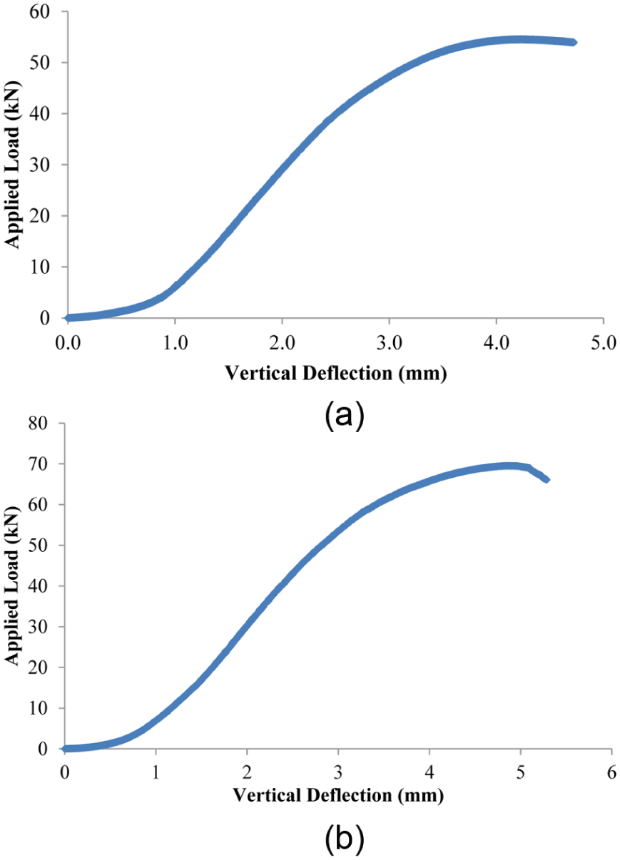
Plot of applied load versus deflections for 200 × 45 × 1.6 LSB with bearing length = 100 mm: (a) EOF load case (test specimen 7) and (b) IOF load case (test specimen 19).
The web crippling capacities of the tested LSB specimens were computed based on the AS/NZS 4600 (SA, 2005) design equation (equation (1)). In these calculations, the clear web heights (d1) of LSBs in Table 3 were used since the outside corners are filled with weld material unlike the rounded corners in standard cold-formed channel sections. Table 4 compares the predicted and experimental web crippling capacities. The web crippling coefficients used in the capacity predictions were taken for unfastened, stiffened or partially stiffened flanges and one-flange loading or reaction based on the support and flange conditions provided in Table 2. These web crippling coefficients as per AS/NZS 4600 (SA, 2005) are as follows. The inner bent radii of LSBs were taken as zero in these calculations


The comparison in Table 4 shows that for EOF load case, the test to predicted web crippling capacity was 1.32 while the respective coefficient of variation (COV) is 0.159. The mean value for IOF load case was 1.36 while the respective COV is 0.120. From these mean values, it can be concluded that the web crippling capacity predictions for LSBs based on AS/NZS 4600 (SA, 2005) are about 30% conservative for both EOF and IOF load cases. As the standard design equation was developed for open cold-formed steel sections, web crippling capacities of LSBs with rectangular hollow flanges are overdesigned according to the design equation in AS/NZS 4600 (SA, 2005) and AISI S100 (AISI, 2012); thus, the coefficients provided in Table 2 are no longer applicable for LSBs. Therefore, a new set of web crippling coefficients for equation (1) are proposed for the LSBs with rectangular hollow flanges to accurately predict their web crippling capacities.
Keerthan et al. (2013) found that AS 4100 (SA, 1998) predictions compared reasonably well with test results for LSBs subject to combined bending and shear action, which reinforces that the behaviour of the LSB is more in line with that of hot-rolled sections. This is likely to be due to the stiff hollow flanges which contribute to a large proportion of the bending capacity much the same as in hot-rolled beams.
AS 4100 (SA, 1998) provides a procedure for checking for adequate capacity against bearing yielding and bearing buckling based on the load dispersion method. The bearing yield capacity of an un-stiffened web at the web-to-flange junction is calculated based on the assumption of a uniformly distributed bearing load based on a 1:2.5 dispersion through the flange.
The nominal bearing buckling capacity of a web without transverse stiffeners is computed as the axial load capacity of a compression member of area twbb, with a slenderness ratio equal to 2.5d1/tw. Here, bb is the total bearing width at the neutral axis, obtained by dispersions at a slope of 1:1 from the web–flange junction.
In order to check the applicability of AS 4100 (SA, 1998) design equations, the web crippling capacities of the tested LSB specimens were also computed based on the AS 4100 (SA, 1998) design equation. Table 4 compares the predicted and experimental web crippling capacities. It shows that, for EOF load case, the test to predicted web crippling capacity was 1.20 while the respective COV is 0.175. The mean value for IOF load case was 1.72 while the respective COV is 0.246. Test results thus show that AS 4100 (SA, 1998) are conservative for both EOF and IOF load cases.
Proposed web crippling capacity equations
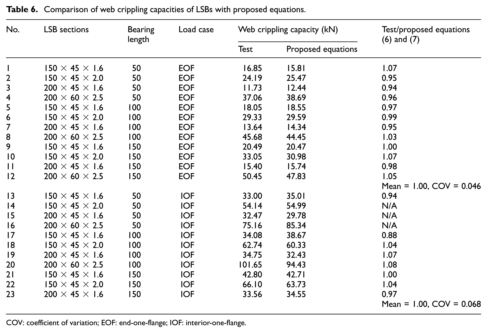
As discussed earlier, the current deign equation for web crippling capacities is too conservative for the design of LSB sections. A new set of web crippling coefficients (C, Cr, Cl and Cw) substituting the existing AS/NZS 4600 (SA, 2005) coefficients are proposed based on the experiments conducted on four different LSB sections under EOF and IOF load cases. The inside bent radius (ri) was assumed to be zero for LSB sections because of the welded web–flange juncture. The new web crippling capacity (Rb) design equations for EOF and IOF load cases are given in equations (6) and (7). The corresponding web crippling coefficients applicable for LSB sections are given in Table 5. The ultimate web crippling capacities computed according to the new proposed equations are compared with the test results in Table 6. The mean value for the experimental capacity results to the capacities computed from the new proposed equations is 1.00 and the COV is 0.046 for EOF load case. For IOF load case, these values are 1.00 and 0.068, respectively. The comparison shows very good agreement between the test results and the proposed web crippling design equations for LSB sections
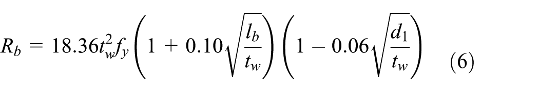
for EOF load case
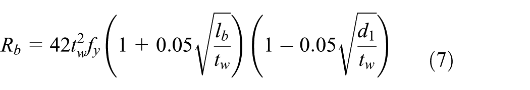
for IOF load case
Proposed web crippling coefficients for LSBs.

COV: coefficient of variation; EOF: end-one-flange; IOF: interior-one-flange.
Not applicable since ri is considered to be zero for LSBs.
Comparison of web crippling capacities of LSBs with proposed equations.
COV: coefficient of variation; EOF: end-one-flange; IOF: interior-one-flange.
Proposed equations (equations (6) and (7)) are only valid for the tested LSB sections. Numerical analyses are being carried out to improve the proposed equations.
The AISI S100 standard (AISI, 2012) recommends a statistical model to determine the capacity reduction factor (
where Mm, Vm are mean and COV of the material factor (1.1, 0.1); Fm, Vf are the mean and COV of the fabrication factor (1.0, 0.05); Vq is the COV of load effect (0.21);
Using equation (8) with the mean and COV values in Table 6 gave capacity reduction factors (ϕw) of 0.90 and 0.89 for EOF and IOF load cases. Therefore, it is recommended to use ϕw factors of 0.90 and 0.85 for EOF and IOF load cases, respectively.
DSM
In addition to the standard design procedure of effective with method, an alternative design method called the DSM has been adopted in AS/NZS 4600 (SA, 2005) and AISI S100 (AISI, 2012) design standards. However, there is no DSM available on predicting the web crippling capacities of cold-formed steel sections. This section presents a newly developed DSM for predicting web crippling capacities of LSBs.
The new DSM web crippling capacity design equations proposed in equation (9) is similar to the design equations for section moment capacity of beams subjected to local buckling. The nominal web crippling capacity (Pu) based on DSM considers elastic buckling capacity in web crippling (Pcr) and web yield capacity (Py). The original power coefficient value of 0.4 was substituted by 0.73 for IOF loading case based on the experimental studies on LSB sections reported in this article. A similar approach can be used for EOF load case. The buckling coefficient (k) in equation (10) was calculated based on equation (13) for IOF load case, which was proposed by Duarte and Silvestre (2013) for channel beams. Slenderness (λ) was calculated using equation (12).
For IOF load case, the web crippling failures of LSBs occurred within the clear web height between their two hollow flanges as seen in Figures 12 and 13. Keerthan et al. (2014) found that web crippling failures of LSBs occurred within the clear web height (d1) for ETF and ITF load cases. For LSBs, outside corners are filled with weld material unlike the rounded corners in standard cold-formed channel sections. Therefore, clear height of web (d1) was considered to compute the elastic buckling capacities (equation (10)) and equivalent web yield capacities (equation (11))


where kIOF is the buckling coefficients of LSB under IOF load case, l is the length of test specimen, lb is the bearing plate length and d1 is the clear height of web.
Table 7 shows the buckling coefficients of steel beams under IOF load case obtained from Duarte and Silvestre (2013) (equation (13) for cold-formed steel channel sections); Johansson and Lagerqvist (1995) (equation (14) for plate girders) and Bock and Real (2014) (equation (15) for stainless steel hat sections). Since the buckling coefficient (k) given in equation (13) was proposed by Duarte and Silvestre (2013) for cold-formed steel channel sections under IOF load case, this equation was used to calculate the approximate buckling load (Pcr) of LSB section under IOF load case
Buckling coefficients of steel beams under IOF load case.
Since the equations proposed by Duarte and Silvestre (2013), Johansson and Lagerqvist (1995) and Bock and Real (2014) are complex and were validated only for plate girders under IOF load case, further research studies are currently under way to obtain the buckling coefficients of LSB sections accurately under both EOF and IOF load cases using finite element analyses. It is proposed that a suitable buckling coefficient equation (kprop) can be developed to include the effect of inside bent radius (ri), web depth (d1), bearing length (ℓb), flange width (bf) and thickness (tw) of the sections (equation (16)). This equation is in a similar form of AISI S100 (AISI, 2012) and AS/NZS 4600 design equation for web crippling capacities. This proposed equation is not complicated compared to equations (13) to (15)
where Cb is the general coefficient, Cb,r is the coefficient of inside bent radius to thickness ratio, Cb,w is the coefficient of web slenderness ratio, Cb,ℓ is the coefficient of bearing length to thickness ratio and Cb,f is the coefficient of flange width-to-thickness ratio.
This method to predict the buckling coefficients of hollow flange channel beams under EOF and IOF load cases can be extended to other cold-formed steel sections such as unlipped channels, lipped channels and channels with web ribs. The equivalent web yield capacities in web crippling are given by equation (11), which considers a 45° load distribution from the bearing plate edges to the centre for IOF load case. These equivalent web yield capacities also agree well with the yield-line model proposed by Young and Hancock (2001). The effect of outside bent radius (ro) (Figure 1) on the web yield capacity was not considered in these two equations. However, for LSB sections, the outside bent radius (ro) is equal to 2tf, which needs to be considered in the design equations. Further research studies will be undertaken using finite element analyses to investigate the effect of outside bent radius (ro) on the yield capacity in web crippling (Py).
The accuracy of the proposed DSM equations was investigated by plotting the experimental results of LSBs in a non-dimensional format (Pu/Py vs λ) together with the DSM capacity curves in Figure 15 for IOF load case. Comparisons in this figure show a good agreement, and thus, it can be concluded that the proposed DSM equations predict the web crippling capacities of tested LSBs accurately under IOF load case reasonably well. A similar approach can be used for EOF load case. Further research is on-going on the applicability of the proposed DSM expressions for a wide range of LSB sections.

Direct strength method–based design equations – IOF load case.
Conclusion
This research article has presented the details of web crippling experimental studies performed on four different cold-formed hollow flange channel sections known as LSB with rectangular hollow flanges. The tests were carried out under EOF and IOF load cases with different bearing plate lengths. The test results were compared with the current web crippling design equations given in AS/NZS 4600 (SA, 2005) and AISI S100 (AISI, 2012). It was found that the current design standards predicted the web crippling capacities of LSB sections conservatively, which will result in the overdesign of the sections. Therefore, a new set of equations was proposed for LSB sections under both EOF and IOF load cases within the current design provisions to accurately predict their web crippling capacities. In addition, design equations based on DSM were also proposed for LSB sections. As there are no DSM expressions to predict the web crippling capacities of cold-formed steel sections, the newly proposed DSM equations for LSB sections can also be modified to compute the web crippling capacities of other cold-formed steel sections. Further numerical studies are on-going to thoroughly understand the web crippling behaviour of LSB sections and to further enhance the design equations in predicting their web crippling capacities accurately.
Footnotes
Acknowledgements
The authors would like to thank William Schuh, Simon Ke and Scott Abbett for their valuable assistance in performing the web crippling tests.
Declaration of Conflicting Interests
The author(s) declared no potential conflicts of interest with respect to the research, authorship and/or publication of this article.
Funding
The author(s) disclosed receipt of the following financial support for the research, authorship and/or publication of this article: The authors would like to thank Australian Research Council for their financial support, and the Queensland University of Technology for providing the necessary facilities and support to conduct this research project.