




Abstract
For fiber-reinforced polymer–strengthened reinforced concrete beam, one of the major failure modes is debonding failure. The premature failure led to the rapid development of analytical solutions on interfacial stresses. Existing analytical solutions usually fail to consider the effect of shear deformation in the adherends completely. In this study, a new theoretical solution is proposed based on Timoshenko beam theory. The coupled governing differential equations of interfacial stresses are solved by weighted residual method based on the least squares principle. The effect of shear deformation on both interfacial shear and normal stresses is obtained simultaneously with relatively simple expressions of interfacial stresses. Moreover, the proposed solution is compared with other previous solutions to further validate the effect of adherend shear deformation on interfacial stresses. Overall, the parametric study demonstrates that the thicker adhesive layer, thinner fiber-reinforced polymer, or lower fiber-reinforced polymer modulus would effectively reduce the peak interfacial stresses at the fiber-reinforced polymer plate end.
Keywords
Introduction
In the last two decades, bonding fiber-reinforced polymer (FRP) composite to the tension face of reinforced concrete (RC) beams using an epoxy adhesive layer has been the most popular structure strengthening technique. FRP-based strengthening technique has enormous advantages, such as high strength and low weight, over the traditional ones. FRP has been widely used in flexural strengthening, shear strengthening, and compression strengthening for concrete structure. For FRP-strengthened RC beams, the most common failure mode is the FRP end debonding failure. Such brittle FRP debonding failure from the RC beam is initiated by the high interfacial shear and normal stresses at the FRP ends. Recently, experimental and theoretical studies on plate-end debonding have been carried out. Important works are introduced as follows.
Smith and Teng (2001) compared their proposed closed-form solution with that of Vilnay (1988), Roberts (1989), and Malek et al. (1998). The comparison shows that the solution of Smith and Teng (2001) is more simplified and accurate and can be applied to more different load conditions. It has been recognized as the most popular solution for interfacial stress prediction. However, the solution ignored shear deformation effect of the RC beam and FRP plate to uncouple the governing differential equations. Therefore, it is inaccurate for the stress distribution prediction of FRP-strengthened RC beams.
Based on the study by Smith and Teng (2001), Yang and Wu (2007) proposed a closed-form solution considering the shear deformation effect. The superposition principle was used to represent interfacial stress as a sum of the solution of Smith and Teng (2001) and a particular solution due to the adherend shear deformation. The particular solution was expressed by Fourier series with a linear supplementary item and the unknown constants are obtained by Galerkin procedure. Compared with the solution of Smith and Teng (2001), this solution proposed by Yang and Wu (2007) is an improved one by considering the adherend shear deformation effect on interfacial shear stress. Moreover, the Galerkin procedure successfully solved the coupled governing differential equations. However, Yang and Wu (2007) did not give some key parameters in the example evaluating the effect of shear deformation, such as the shear modulus for the RC beam and FRP. Meanwhile, a number of unknown constants should be calculated in the Fourier series, which makes the whole procedure complicated and leads to too complex expressions for interfacial stress to be adopted into design rule.
Abdelouahed (2006) and Tounsi et al. (2009) applied the theory proposed by Tsai et al. (1998) into interfacial stress analysis for FRP-strengthened RC beam with the consideration of the effect of longitudinal shear deformation. Using the horizontal force equilibrium and assuming a parabolic longitudinal shear stress distribution along the thickness direction of the RC beam and FRP, Tounsi et al. (2009) obtained expressions of interfacial stresses including adherend shear deformation effect. Compared with the solution proposed by Smith and Teng (2001), their solution first observed that shear deformation lowered interfacial stresses and evaluated this effect. However, the method proposed by Tounsi et al. (2009) cannot be applied to study the effect of the shear deformation on interfacial normal stress accurately. Their solution is incomplete due to the absence of the effect of shear deformation on interfacial normal stress.
Narayanamurthy et al. (2011) studied the effect of the adherend shear deformation on interfacial stress distribution in plated beams under an arbitrary load. In accordance with Tounsi et al. (2009), Narayanamurthy et al. (2011) also used the horizontal force equilibrium and assumed a parabolic longitudinal shear stress distribution along the thickness direction of the RC beam and FRP to predict interfacial shear stress. In order to consider the interfacial normal stress, Narayanamurthy et al. (2011) used Timoshenko beam theory to account for the transverse shear deformation. Compared with the solution of Tounsi et al. (2009), this solution studied the effect of shear deformation on interfacial normal stress. Instead of other solutions, this solution can be used for RC beams subjected to arbitrary load condition rather than uniform distributed load or single point load. However, their solution is an approximate one due to the assumption adopted in the interfacial shear stress analysis, which slightly compromised the accuracy of their solution.
Edalati and Irani (2012) also studied the effect of shear deformation on interfacial stress for FRP-strengthened RC beams. Edalati and Irani (2012) treated the beam, the adhesive, and FRP as Timoshenko beams and used Timoshenko beam theory to consider the adherend shear deformation for both interfacial shear stress and interfacial normal stress. Compared with the solution of Yang and Wu (2007), Edalati and Irani (2012) proposed a new method to solve the coupled governing differential equations and obtained an improved result.
Narayanamurthy et al. (2016) proposed another improved closed-form solution of interfacial stresses in plated beam. Instead of Narayanamurthy et al. (2011), Timoshenko beam theory was applied to include the effect of shear deformation for both interfacial shear and normal stresses, which made their solution more rigorous. As with Narayanamurthy et al. (2011), this solution can also be applied to RC beams subjected to arbitrary load condition. Moreover, proper finite element model was selected to verify the correctness of analytical solutions. A comparison shows that the solution is in close agreement in both interfacial shear and normal stresses with those obtained by the finite element analysis. Their study showed that the effect of shear deformation of adherend is more significant on interfacial normal stress than interfacial shear stress. This conclusion does not agree with the conventional opinion that interfacial shear stress is more sensitive to the shear deformation. More researches are needed to further testify the new finding presented in Narayanamurthy et al. (2016).
Rabinovitch and Frostig (2000, 2001), Shen et al. (2001), and Yang et al. (2004) studied high-order analytical solutions to determine interfacial shear and normal stresses. Rabinovitch and Frostig (2000) only listed the boundary condition to determine the constants of integration but did not provide the explicit expressions for interfacial stress. Developing this solution into a design rule appears impossible. Shen et al. (2001) proposed another high-order analytical solution given the explicit expressions for interfacial stress. However, Shen’s solution failed to consider the adherend shear deformation effect. When the beam is short span or the adhesive layer is thinner, the effect of shear deformation is not negligible. Thus, Shen’s solution cannot be properly used to analyze the interfacial stress.
Some other analytical solutions are carried out to investigate the interfacial stresses in FRP-strengthened beam, such as Narayanamurthy et al. (2010), and Ye (2001), Stratford and Cadei (2006), Yang et al. (2008,2009), and Rasheed et al. (2011). These solutions study the effects of various factors like temperature and crack on interfacial stresses. These studies make the analytical solutions suitable for more conditions, improve the accuracy, and deepen the understanding of the theoretical principle.
For an ordinary beam, the adherend shear deformation does not greatly influence interfacial stress and is negligible when it predicts interfacial stress. Based on Timoshenko beam theory, shear deformation has a remarkable effect on interfacial stress and cannot be ignored for short-span or sandwich beam. Meanwhile, interfacial stress is a critical factor for FRP plate-end debonding failure and such stress is very sensitive to the adherend shear deformation. The shear deformation will significantly affect interfacial stresses and this effect must be considered.
In this article, the beam and the FRP are assumed to be Timoshenko beams. Based on Timoshenko beam theory, the effects of adherend shear deformation on interfacial shear and normal stresses are included. The application of shear deformation to the Timoshenko beam results in the coupled governing differential equations of interfacial stresses. The weighted residual method is applied to solve the coupled equations. By assuming the trial functions that satisfy the boundary conditions and the use of least squares, the unknown constants of the trial functions are obtained and the expressions of interfacial stresses are successfully determined in a relatively simple form. Furthermore, comparison between the proposed solution and those existing solutions is made through a carbon fiber–reinforced polymer (CFRP)-strengthened RC beam. The comparison clearly indicates the effect of shear deformation on interfacial shear and normal stresses, respectively. The proposed solution is an improved solution through which the researchers can preferably evaluate the effect of shear deformation on interfacial shear and normal stresses. The solving procedure and expressions of interfacial stresses are relatively simple and preferably accurate. Finally, the influence of material and geometric parameters of the FRP plate and the adhesive layer on the proposed solution is analyzed by a parametric study and some suggestions are offered for the design.
Governing differential equations and general solution of interfacial shear and normal stresses
Basic assumptions
Based on the study by Tounsi et al. (2009) and Narayanamurthy et al (2011), basic assumptions for the prediction of interfacial stress are made as follows:
All materials are performed in a linear elastic way.
The bond between the RC beam and FRP plate is perfect, and no slip occurs at the interface.
The bending deformation of the adhesive layer is negligible; the deformation is induced by the axial force, shear force, and bending moment.
The stress in the adhesive layer does not change through the direction of thickness.
The curvature of the beam and FRP are the same. This assumption is only used in interfacial shear stress analysis.
Interfacial shear stress
A simply supported RC beam strengthened with bonded FRP plate is shown in Figure 1. A differential section dx can be cut from the FRP-strengthened beam (Figure 1) and is shown in Figure 2. The RC beam, FRP plate, and the adhesive layer are denoted as 1, 2, and a, respectively. Interfacial shear stress and normal stress are denoted as τ(x) and σ(x) and the direction of stress is illustrated in Figure 2. Figure 2 also shows the positive direction of the bending moment M(x), shear force V(x), and axial force N(x).

Simply supported RC beam strengthened with FRP plate.

Differential segments of a RC beam bonded with FRP plate.
Based on the work of Smith and Teng (2001), the expression of interfacial shear stress can be given as

where u(x) and v(x) are the horizontal and vertical displacement at any point in the adhesive layer, respectively. Ga is the shear modulus of the adhesive layer. Differential of the above equation with respect to x gives

According to the assumptions in section “Governing differential equations and general solution of interfacial shear and normal stresses,” the horizontal displacement (u(x)) varies linearly across the adhesive thickness ta and then the following equations exist


where u1(x) and u2(x) are the horizontal displacements at the base of the RC beam and the top of FRP, respectively.
According to the work by Smith and Teng (2001), the strain at the base of adherend 1 (RC beam) and at the top of adherend 2 (FRP) can be obtained as follows


where y1 and y2 are the distances from the base of the RC beam and the top of FRP plate to their own neutral axis, respectively. E and G are the elastic modulus and the shear modulus, respectively. I is second moment of area. A is the cross section area and b2 is the width of FRP. q is the uniform distributed load subjected on the beam. κ is the Timoshenko shear coefficient. For rectangle cross section, κ is 5/6.
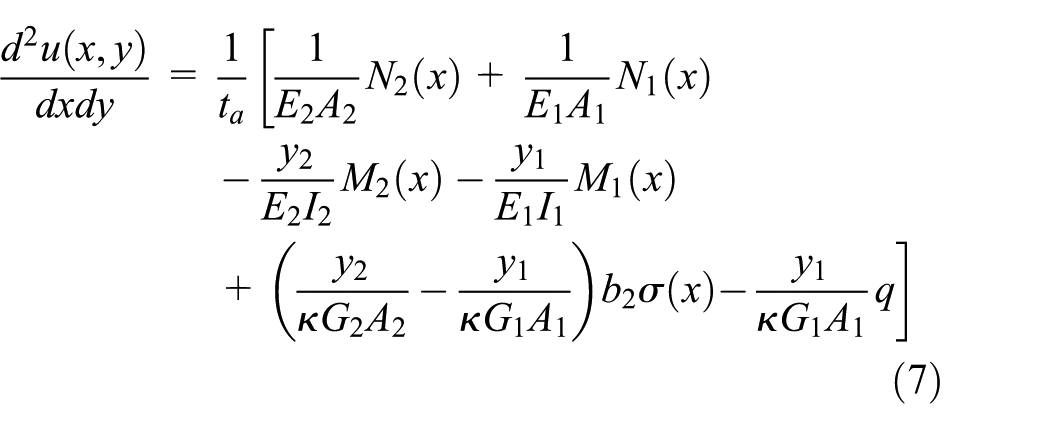
On the right side of equations (5) and (6), the first item including N(x) is the axial force–induced normal strain. The second item including M(x) is the moment-induced normal strain and the third item including σ(x) is the shear force–induced normal strain.
Substituting equations (5) and (6) into equation (4), the following equation is obtained
Meanwhile, the second term on the right side of equation (2) is related to vertical displacement. Based on the study by Smith and Teng (2001), the deformation of adhesive layer in the thickness-wise direction is uniform. In this study, the vertical displacement of adhesive layer can be represented by the vertical displacement in the middle of the adhesive layer

where v1 and v2 are the vertical displacements of the beam and FRP, respectively.
Based on Timoshenko beam theory, the following equations can be determined


By differentiating equation (14) twice and substituting equations (15) and (16), the following equation is obtained

As mentioned in section “Governing differential equations and general solution of interfacial shear and normal stresses,” the curvatures of the RC beam and FRP plate are identical. Based on the study by Smith and Teng (2001), the axial forces and bending moments in the RC beam and FRP plate are described as follows




where
Substitute equations (7) and (11) into equation (2) and differentiate equation (2) with respect to x once. Then, applying equations (12) to (15), the governing differential equation can be represented as follows

where




Interfacial normal stress
Based on the study by Smith and Teng (2001), the formula of the interfacial normal stress of a RC beam strengthened with FRP plate is given as

Based on the study by Smith and Teng (2001), the equilibrium equations of the RC beam and the FRP plate are described as follows




Differentiating equation (17) four times and then substituting equations (9) and (10) as well as equations (18) to (21) into equation (17), the governing equation of interfacial normal stress can then be expressed as follows

where
General solution of interfacial shear and normal stresses
Equations (16) and (22) are the governing differential equations for interfacial shear and normal stresses, respectively. The governing differential equations of interfacial shear and normal stresses are clearly coupled. To solve the coupled equations, the weight residual method is used based on the boundary conditions of uniform distribution load and the governing differential equations.
Equations (16) and (22) are the governing differential equations for interfacial shear and normal stresses, respectively.
To solve the coupled equations, the solution of interfacial shear and normal stresses is divided into two irrelevant parts. One is an ordinary part that does not contain the items of shear deformation, in which the corresponding governing differential equations are not coupled based on the study by Smith and Teng (2001) and the solution can be easily found. The other is a special part that is only related to the shear deformation, where the corresponding governing differential equations are coupled and the weight residual method is applied to solve the equations. This methodology simplifies the procedure because part of the solution is known and the rest of the part is easier to be obtained. Interfacial shear and normal stresses can be expressed as follows

where τ0 and σ0 are the ordinary parts which satisfy the governing differential equations and the boundary conditions described in the study by Smith and Teng (2001). τs and σs are the special parts.
Based on the solution of Smith and Teng (2001), the following solution can be obtained

where

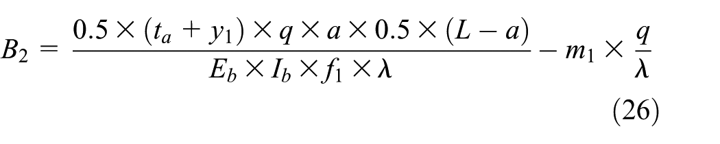
Then, the interfacial normal stress can be expressed as

where
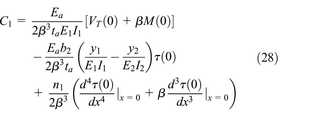

where
Substituting equation (23) into the governing equations (16) and (22), and according to the governing differential equations in the study by Smith and Teng (2001), which are satisfied by τ0 and σ0, the governing differential equations for τs and σs are then determined as follows


The boundary conditions are




where ls is the bond length of FRP.
The weight residual method is used to find the solution of τs and σs. Based on the numbers of governing differential equations and corresponding boundary conditions, the proper number of unknown constants in the trial functions is determined. Trigonometric function expressions with constant term are selected as the trial functions of τs and σs to improve the accuracy, and the hypothetical expressions are as follows


Present solution only has three unknown constants for interfacial shear and normal stresses, respectively. It means the expressions obtained by present method will be simpler than the expressions obtained by Yang and Wu (2007).
To simplify the process, the trial functions of τs and σs satisfy the boundary conditions in equations (32) to (35). Substituting equations (36) and (37) into equations (32) to (35), unknown constants of the trial functions can be determined, whereas others can be expressed as functions of α1 and α2



The special part of the solutions τs and σs can then be expressed as the functions of α1 and α2. Usually, the governing differential equations cannot be completely satisfied by the trial functions and the residuals of the governing equations are then generated. By substituting equations (36) and (37) into equations (30) and (31) and applying equations (38) to (41), the residuals of equations (30) and (31) can be determined as functions of α1 and α2 and denoted as R1 and R2, respectively. Based on the principle of least squares, the weight function can be determined. The equations to eliminate the residuals can be determined as follows


Equations (42) and (43) are linear equations of α1 and α2. α1 and α2 can be determined using MATLAB. The expressions of τs and σs can then be determined by α1 and α2, respectively. Finally, the expressions of interfacial shear and normal stresses can be obtained by equation (24).
Comparison of analytical solutions
Analytical model and parameters
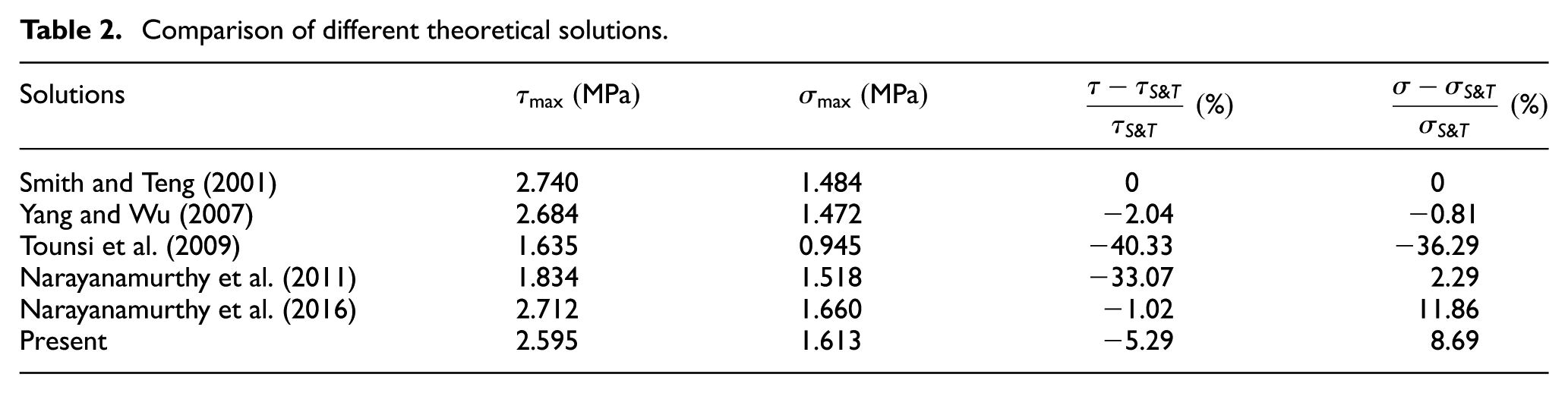
In this section, an RC beam strengthened by CFRP plate under a uniform distributed load is taken as an illustrative example. The beam span, the distance from the support to the plate end, and the uniform load density are 3000 mm, 300 mm, and 50 kN/m, respectively. The geometry and material parameters of the beam, FRP, and the adhesive layer are shown in Table 1. The results of proposed solution are compared with solutions proposed by Smith and Teng (2001), Yang and Wu (2007), Tounsi et al. (2009), and Narayanamurthy et al. (2011, 2016) as shown in Table 2.
Geometry parameters and material properties of bonded beam.

RC: reinforced concrete; CFRP: carbon fiber–reinforced polymer.
Comparison of different theoretical solutions.
Results and discussion
As shown in Table 2, comparison between different analytical solutions shows that the adherend shear deformation reduces the maximum value of interfacial shear stress. The difference percentages in interfacial shear stress vary from solution to solution. It is clear that the difference percentages of Tounsi et al. (2009) and Narayanamurthy et al. (2011) are much larger than the other three solutions. This may be due to the approximation generated by the assumption applied in the interfacial shear stress analysis. Among the present solution, Yang and Wu (2007), and Narayanamurthy et al. (2016), the difference percentages are 5.29%, 2.04%, and 1.02%, respectively. The difference among these three solutions is relatively small.
The interfacial normal stresses predicted by different solutions appear to have different tendency. Yang and Wu (2007) as well as Tounsi et al. (2009) reported a reduction in interfacial normal stress while the rest solutions reported an increase. Based on the finite element study in Narayanamurthy et al. (2016), the adherend shear deformation increased the interfacial normal stress. It is reasonable to believe that the solutions of this article and the solution of Narayanamurthy et al. (2011, 2016) are more accurate in predicting interfacial normal stress.
Figure 3 shows the comparison of interfacial shear stress obtained by the proposed approach with those by the approaches from Tounsi et al. (2009) and Smith and Teng (2001). Peak interfacial shear stress reduced after considering shear deformation, which means that shear deformation reduces the degree of interfacial shear stress concentration at the plate end. The comparison between Tounsi et al. (2009) and present solution indicates that Tounsi et al. (2009) predicted a quite larger reduction in the interfacial shear stress and a more uniform distribution of stress along the FRP length direction. However, the predictions by finite element analysis in Teng et al. (2002) and Zhang and Teng (2010) indicate that the interfacial shear stress varies significantly at the plate end. This deviation shows that the solution of Tounsi et al. (2009) is an approximate solution.

Comparison of interfacial shear stress.
Figure 4 shows the comparison of the interfacial normal stress from the proposed approach with that of the approaches by Tounsi et al. (2009) and Smith and Teng (2001). Peak interfacial normal stress predicted by Tounsi et al. (2009) is also reduced significantly while the present solution predicts an increase. This reduction is attributed to the peak interfacial shear stress because the interfacial shear stress is included in the governing differential equation of the interfacial normal stress. Moreover, the reduction predicted by Tounsi et al. (2009) is not agreed with the prediction by the finite element analysis reported in Narayanamurthy et al. (2016) while the present solution is in good agreement with the finite element analysis.
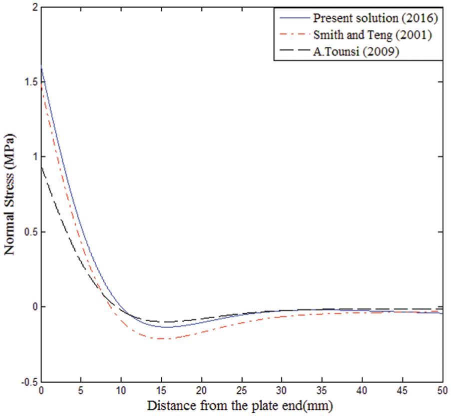
Comparison of interfacial normal stress.
In conclusion, solutions of Tounsi et al. (2009) and Narayanamurthy et al. (2011) are relatively inaccurate for the interfacial shear stress due to the approximation generated by the assumption applied in analysis. The solution of Yang and Wu (2007) well predicts the interfacial shear stress but may be inaccurate to predict the interfacial normal stress. Present solution and the solution of Narayanamurthy et al. (2016) are relatively good solutions which are in good agreement with the finite element analysis. The solution of Narayanamurthy et al. (2016) is rigorous, but its solving procedure and expressions of interfacial stresses are complex. For present solution, its solving procedure and the expressions of interfacial stresses are relatively simple. Comparison between the solution of Narayanamurthy et al. (2016) and present solution indicates that present solution is a preferable solution for design rules.
Parametric study
In this section, a parametric study is conducted to investigate the effect of geometry and material parameters on interfacial stresses.
Elastic modulus of adhesive layer Ea
Figure 5 depicts the effect of adhesive layer’s elastic modulus on interfacial shear and normal stresses. Three different values of adhesive elastic modulus were considered: 1, 2, and 4 GPa. As shown in Figure 5(a), the differences in interfacial shear and normal stresses due to different adhesive elastic modulus are obvious. The elastic modulus of the adhesive layer has a considerable effect at the plate end but the effect reduces with the increase in distance from the plate end. With the increase in elastic modulus, interfacial shear and normal stresses increase proportionally.

Effect of adhesive elastic modulus on interfacial stresses: (a) shear stress and (b) normal stress.
Adhesive layer thickness ta
Figure 6 presents the effect of adhesive layer thickness on interfacial shear and normal stresses. Three different values of adhesive thickness are considered: 2, 4, and 8 mm. It is clear that the variation of thickness has a considerable effect on both interfacial shear and normal stresses. With the increase in adhesive layer thickness, interfacial shear and normal stresses decrease proportionally. However, the difference between various thicknesses is smaller as the distance from the plate end increases, indicating that adhesive layer thickness only affects the stress distribution within a small distance. Even a small change in the thickness can significantly affect the degree of the stress concentration at the plate end.
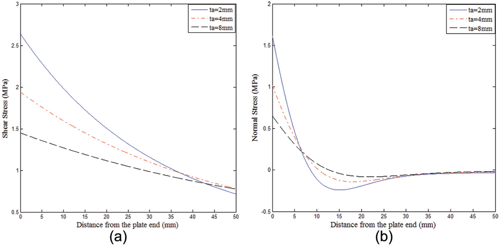
Effect of adhesive thickness on interfacial stresses: (a) shear stress and (b) normal stress.
Elastic modulus of FRP plate Ep
Figure 7 shows the effect of FRP plate’s elastic modulus on interfacial shear and normal stresses. Three different values of FRP elastic modulus are considered: 100, 150, and 200 GPa. For both interfacial shear and normal stresses, the variation of FRP elastic modulus has an obvious effect. With the increase in elastic modulus, interfacial shear and normal stresses increase simultaneously. However, the effect on interfacial shear stress is more obvious than that of interfacial normal stress, indicating that interfacial shear stress is more sensitive to FRP elastic modulus. The effect of FRP elastic modulus on the shear stress distribution does not decrease with the increase in the distance from the plate end.

Effect of adhesive elastic modulus on interfacial stresses: (a) shear stress and (b) normal stress.
FRP plate thickness tp
Figure 8 demonstrates the effect of FRP thickness on interfacial shear and normal stresses. Three different values of FRP thickness are considered: 4, 6, and 8 mm. For both interfacial shear and normal stresses, the variation of the thickness has a considerable effect. With the increase in FRP thickness, interfacial shear and normal stresses increase proportionally. Interfacial shear and normal stresses are both sensitive to FRP thickness. The effect of FRP elastic modulus on interfacial shear stress does not decrease with the increase in the distance from the plate end.

Effect of FRP thickness on interfacial stresses: (a) shear stress and (b) normal stress.
FRP plate bond length ls
Figure 9 shows the effect of FRP bond length on interfacial shear and normal stresses. Three different values of FRP plate bond length are considered: 2200, 2400, and 2600 mm. For both interfacial shear and normal stresses, the variation of the bond length has a great effect. With the slight increase in FRP bond length, interfacial shear and normal stresses decreased considerably. Interfacial shear and normal stresses are both sensitive to FRP bond length. With the increase in the distance from the plate end, the difference in the interfacial stress between different bond lengths becomes smaller, indicating that the bond length only affects the interfacial stress within a short distance from the plate end.
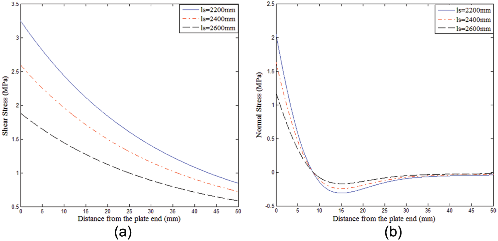
Effect of FRP bond length on interfacial stresses: (a) shear stress and (b) normal stress.
Conclusion
This study presents a new analytical approach for closed-form solution of interfacial shear and normal stresses in FRP-strengthened RC beams. Based on Timoshenko beam theory, the proposed approach takes the shear deformation in the RC beam and FRP plate into consideration for both interfacial shear and normal stresses analysis. The weight residual method based on the least squares principle is successfully applied to solve the coupled governing differential equations of interfacial shear and normal stresses. Meanwhile, an RC beam strengthened by CFRP plate is considered as a typical example to illustrate the shear deformation effect. The following conclusions can be drawn:
The proposed closed-form solution considers the effect of shear deformation in the RC beam and FRP plate for both interfacial shear and normal stresses. Moreover, the proposed analysis can rigorously evaluate the effect of shear deformation due to the application of Timoshenko beam theory. The comparison between different solutions demonstrates that the proposed interfacial stress expressions are reliable to predict interfacial stresses.
The proposed solution introduces the weight residual method into the analysis procedure. The method successfully solves the governing differential equations to determine both interfacial shear and normal stresses. By selecting proper trial function and weight function, this method can determine both interfacial shear and normal stresses with relatively high accuracy in simplified expressions.
The shear deformation in the beam and the FRP reduces the interfacial shear stress. On the contrary, the shear deformation increases the interfacial normal stress. These effects are also demonstrated by the finite element analysis reported in Narayanamurthy et al. (2016). This study shows that the effect of adherend shear deformation is remarkable for both the interfacial shear and normal stresses.
The parametric study shows that adhesive layer thickness has a considerable effect on interfacial stresses. With increasing thickness, interfacial shear and normal stresses both decrease. However, the adhesive layer only affects the interfacial stress distribution within a short distance from the FRP plate end. The thickness and elastic modulus of FRP also have important effects on interfacial shear and normal stresses. With increasing FRP thickness, both interfacial shear and normal stresses increase considerably. With the increase in elastic modulus of FRP, interfacial shear stress greatly increases while the normal stress just slightly increases. Thus, a lower FRP modulus, a thinner FRP plate, and a thicker adhesive layer at the plate end can reduce the peak interfacial shear and normal stresses at the plate end effectively.
Footnotes
Declaration of Conflicting Interests
The author(s) declared no potential conflicts of interest with respect to the research, authorship, and/or publication of this article.
Funding
The author(s) disclosed receipt of the following financial support for the research, authorship, and/or publication of this article: All the authors are grateful for the research funds from National Natural Science Foundation of China (51261120374 and 51378199).