
Abstract
Fire is a common secondary disaster following blast events. Because the strength of steel is sensitive to temperature, the steel structure that survives an explosion threat may collapse in the post-explosion fire. Thus, it is significant to investigate the progressive collapse mechanism of steel structures subjected to explosion and post-explosion fire. This article presents an accurate analytical model for evaluating the progressive collapse potential of a steel frame subjected to a confined explosion and post-explosion fire. The macro-model of the shear tab connection is established, and a material model that can reproduce the nonlinear dynamic behaviour of connections under combined hazard is compiled as subroutines. The finite element package AUTODYN is adopted to calculate the internal blast load to accurately analyse the effect of blast-induced damage on the fire resistance of the steel structure. The analytical results indicate that the gravity columns and columns in the interior moment resisting frames are key components for structural stability under combined hazards. The blast not only results in geometrical damage to the structural members, improving the load–displacement effect, but also leads to failure of the shear tab connections which increases the effective length of the column. Therefore, the failure time of the column under the combined hazard of blast and fire is earlier than the fire only case. Blast damage to the connection may also result in connection failure before column buckling in a fire, leading to local collapse prior to progressive collapse. Moreover, the collapse time–charge weight interaction diagram is generated to determine the weakest area of the steel frame. The membrane action of the floor is the only mode to redistribute load after the failure of the damaged column in a fire. Thus, increasing the reinforcement ratio in the floor may help mitigate the progressive collapse potential of the steel frame.
Introduction
Progressive collapse is defined as ‘the spread of an initial local failure from element to element, eventually resulting in the collapse of an entire structure or a disproportionately large part of it’ (American Society of Civil Engineers (ASCE), 2010). In the past few decades, many incidents of the progressive collapse of structures due to abnormal loads have occurred. For example, a 22-storey building in Ronan Point, London (UK) collapsed when a gas explosion demolished a load-bearing wall in 1968, and half of the Murrah Federal Building in Oklahoma City (USA) collapsed in a terrorist truck bomb attack in 1995. The disastrous collapse of building structures has drawn the attention of engineers and research scholars, and extensive research has been conducted to mitigate the progressive collapse potential of building structures. Based on the research achievements, certain design standards were established in the United States, such as the US General Services Administration (GSA) and United States Department of Defense (DoD) guidelines (DoD, 2013; GSA, 2013). These standards provide design guidelines based on the alternate load path method (APM) to evaluate the potential of progressive collapse for newly designed and existing structures. The APM is a threat-independent methodology that instantaneously removes the critical structural members regardless of triggering events and then analyses the dynamic responses of the remaining structure to determine whether the initial local failure propagates. The APM is regarded as an effective method to analyse the progressive collapse potential of buildings when applied in conjunction with nonlinear dynamic analysis, which is also commonly used in the literatures to investigate the progressive collapse mechanism of building structures under blast loading. For example, Izzuddin et al. (2008a, 2008b) proposed a practical method for progressive collapse assessment of multi-storey buildings. The proposed new approach accommodates simplified as well as detailed models of the nonlinear structural response. Khandelwal et al. (2008, 2009), Fu (2009), Kim and Dawoon (2009), and Kim and Kim (2009) investigated the progressive collapse resistance of different types of steel frames using the APM. Varying model techniques and analysis methods were employed in the above research.
The APM ignores the interaction process between the triggering load and the structural members, which might play an important role in progressive collapse assessment. Thus, a series of research was conducted to update the APM to include the effect of threat loads. Luccioni et al. (2004) and Almusallam et al. (2010) analysed the structural collapse of reinforced concrete (RC) buildings caused by blast loads by taking account of the interaction between the blast load and the structure. In addition to load-bearing columns, beams, connections, and floors were also destroyed by blast waves. Shi et al. (2010) proposed a new method for the progressive collapse analysis of frame structures by considering non-zero initial conditions and initial damage to adjacent structural members caused by explosion to consider the effect of the threat loads. Elsanadedy et al. (2014) evaluated the progressive collapse potential of a multi-storey steel frame in Riyadh when subjected to blast and proposed recommendations to mitigate the potential of progressive collapse. The above research achievements demonstrated that the blast load and the corresponding secondary hazard play important roles in the progressive collapse analysis of building structures under explosion threat.
Fire is a common secondary hazard following explosion for building structures. The fire resistance of the steel structures is not good because the strength of the steel material decreases dramatically when it reaches 600°C. At the same time, the blast load generated by the explosion also causes initial damage to the structural members of the steel structure, thus reducing its fire resistance capacity. Therefore, much more severe damage or even progressive collapse can occur if the steel structure is subjected to explosion and post-explosion fire. One of the examples is the World Trade Center, which was severely damaged by the impact of aircraft and finally collapsed due to the combined effect of the impact, explosion and fire. However, limited studies are available in the literature on the progressive collapse analysis of steel structures under explosions and the secondary fire hazard. Izzuddin et al. (2000), and Song et al. (2000) proposed an integrated method for damage analysis of steel structures under the combination of blast and fire, taking account of the strain rate effect and the thermal properties of steel based on the beam element method. Liew and Chen (2004), and Chen and Liew (2005) proposed fiber element and mixed element methods to analyse the performance of a two-dimensional (2D) steel frame under blast and fire. The blast analysis was performed by explicit solver, whereas the fire analysis was performed by implicit solver. The proposed mixed element method was extended to analyse the three-dimensional (3D) response of a steel frame (Liew, 2008). The above achievements provide some insights into the estimation of the damage to steel structures under the combined hazard of blast and fire. However, the current methods for modelling the nonlinear dynamic behaviour of steel frames under blast and fire are either not accurate or very time-consuming. Thus, an accurate and efficient method should be proposed. At the same time, studies on the progressive collapse mechanism of steel structures subjected to confined explosion and post-explosion fire are still lacking.
In this study, a simplified analytical model to evaluate the progressive collapse potential of steel frames subjected to confined explosion and post-explosion fire is proposed, in which a macro-model for steel connection is established to accurately model its nonlinear dynamic behaviour under blast and fire. A material model used in the connection was compiled as subroutines to incorporate the damage behaviour and failure of connections in progressive collapse analysis. To accurately consider the blast effect, the explicit dynamic commercial package AUTODYN was used to simulate the internal blast loads acting on the members, which determined the initial damage on the steel members. The full process of the structural response was analysed to identify the key components for the overall structural stability under the combined hazards of blast and fire, and the interaction diagram between collapse time and charge weight is established to evaluate the weakest area in the steel frame. Furthermore, the progressive collapse potential of the steel frame with an enhanced floor is evaluated to propose methods and recommendations for prevention of the progressive collapse.
Numerical model setup
Prototype structure
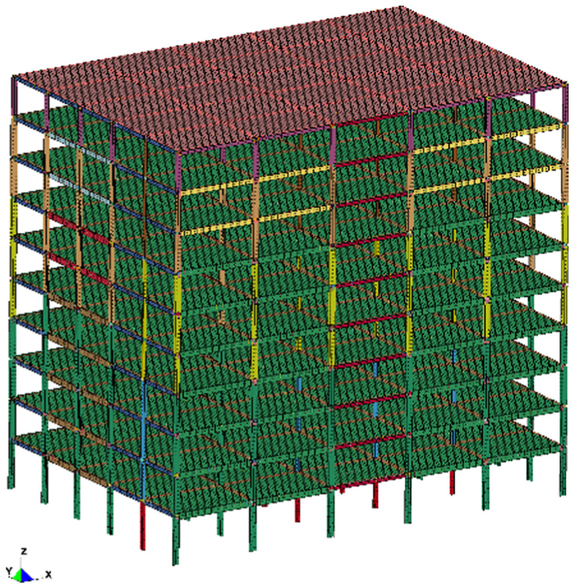
The steel frame building designed by National Institute of Standards and Technology (NIST) of USA was used for the progressive collapse analysis. The building is a 10-storey office building with plan dimensions of 45.7 m by 30.5 m. The typical compartment dimension is 9.14 m by 6.1 m, as shown in Figure 1. The building is designed for Seismic Design Category D (Liang et al., 2006), which results in a special moment frame used as the lateral load resisting system. Beams and columns in the gravity system are connected through shear tab connections (Figure 2(a)) that are bolted using 22 mm, A325 high-strength bolts to 9.5 mm A36 shear tabs. The connections in the moment frame are reduced beam section (RBS) connections with a 50% reduction in the RBS flanges. The composite floor comprises a lightweight, RC slab with 82.5 mm thickness, and a steel deck with 76 mm depth. Steel reinforcement in the RC slab is 0.06 mm2/mm in both directions. A992 structural steel (yield strength Fy = 345 MPa) is used for all beams and columns. Table 1 lists the details of the cross-section sizes, and Figure 3 shows the sketch of cross sections of floor, beam, and column. More design informations are provided by Liang et al. (2006).
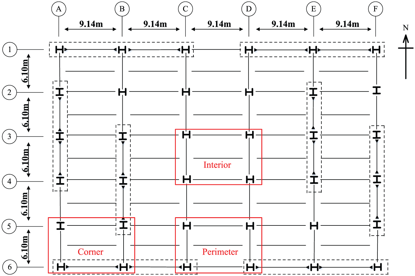
Plan layout for the steel frame.
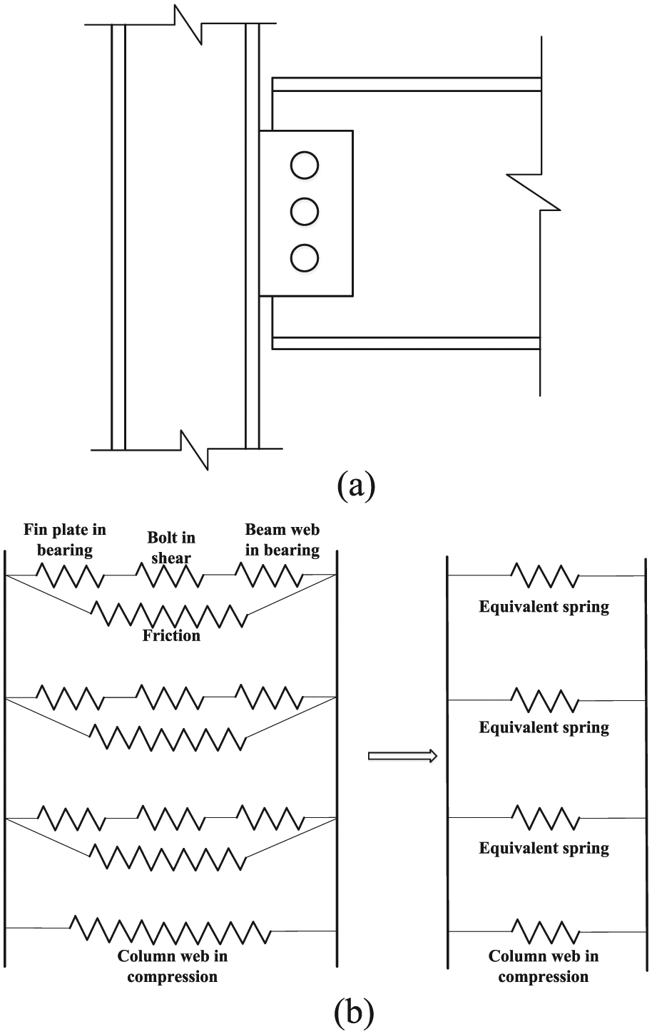
A component-based model for (a) shear tab connection and (b) details of the connection model.
Details of the cross-section sizes.
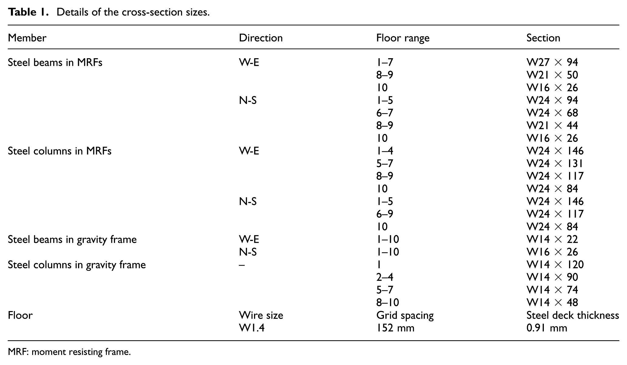
MRF: moment resisting frame.
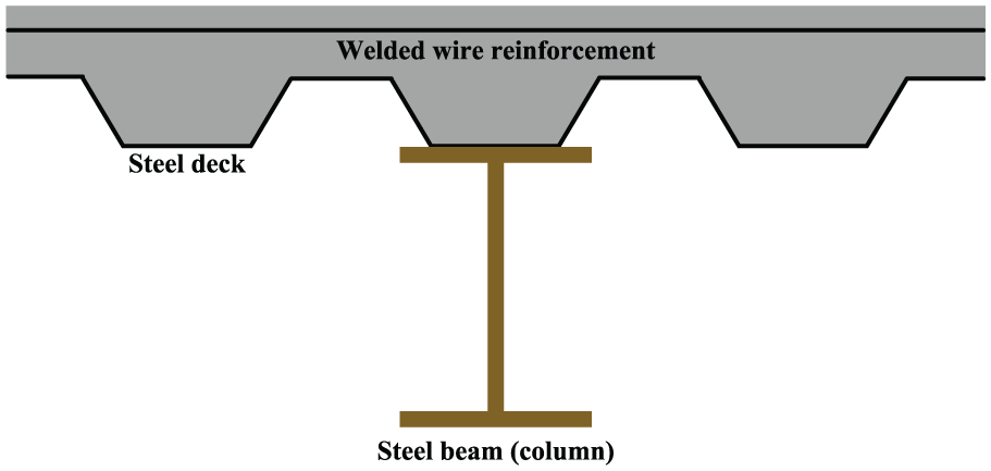
Sketch of cross sections of floor, beam, and column.
Numerical model
The explicit finite element (FE) code LS-DYNA was used to construct the analytical model of the steel frame. Most of the current research in modelling steel structures under blast and fire assume fixed connections between the beams and the columns, regardless of the real connection types (Liew, 2008; Spencer and Shalva, 2012). However, shear tab connections are widely used in steel structures for joining gravity beams and columns, which would carry significant axial, shear forces, and bending moments in blast or fire events and might fail when the interaction of these forces exceed the critical criterion. The connection failure would cause the steel beam to detach from the frame, leading to reduction in the progressive collapse resistance. Therefore, ignoring the modelling of such connections leads to a significant overestimation of the progressive collapse resistance of the steel frame.
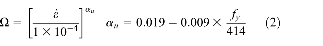
To accurately evaluate the progressive collapse potential of the steel frame, Khandelwal et al. (2008) and Alashker et al. (2011) employed a single beam element to model the shear tab connection, whereas Agarwal and Varma (2014) used spring elements to reproduce the connection response in the collapse analysis. However, the above connection models cannot be used to predict the connection behaviour of the shear tab connection under the combined effect of blast and fire, because they are unable to simultaneously reflect the strain rate effect and the thermal properties of the steel connection in progressive collapse analysis. Therefore, a macro-model of the shear tab connection was established, and a material model that can reproduce the realistic connection behaviour under combined effect of blast and fire was compiled in the subroutines. The shear tab connection was modelled using a beam element with integration points that correspond to individual bolts, whereas the user-defined material model was adopted at the integration points. The stress–strain curves under different loading rates or temperatures were calculated based on the component-based method, which decomposes the shear tab connection into several uncoupled nonlinear springs, representing the bearing of the fin plate, the bearing of the beam web, the shear of the bolt, and the friction at the plate surfaces, as shown in Figure 2(b). The behaviour of each spring is described by a nonlinear force–displacement curve. Sarraj (2007) developed temperature-dependent, force–displacement curves for various springs, but the strain rate effect was not taken into account. However, the strain rate has a strong influence on the behaviour of connections by increasing the yield strength and ultimate strength of the steel material. Malvar (1998) proposed formulae for calculating the dynamic increase factors (DIF) of the steel material, which were used to account for the variable material properties at different loading rates. The DIF for the yield strength (
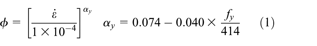
The DIF for the ultimate strength (
where fy is the yield strength of the steel and
Flow chart of establishment of the material model.
Furthermore, an additional spring was set at the location of the beam flange to account for the contact between the beam end and the column flange at large rotation, as shown in Figure 2. There is no force in the spring until the compressive deformation is equal to the gap between the beam end and the column flange. When the beam contacts the column, the stiffness of the spring changes to a large value. The behaviour of the panel zone was not included in the numerical model, as Li and El-Tawil (2014) suggested, to decrease the computational cost.
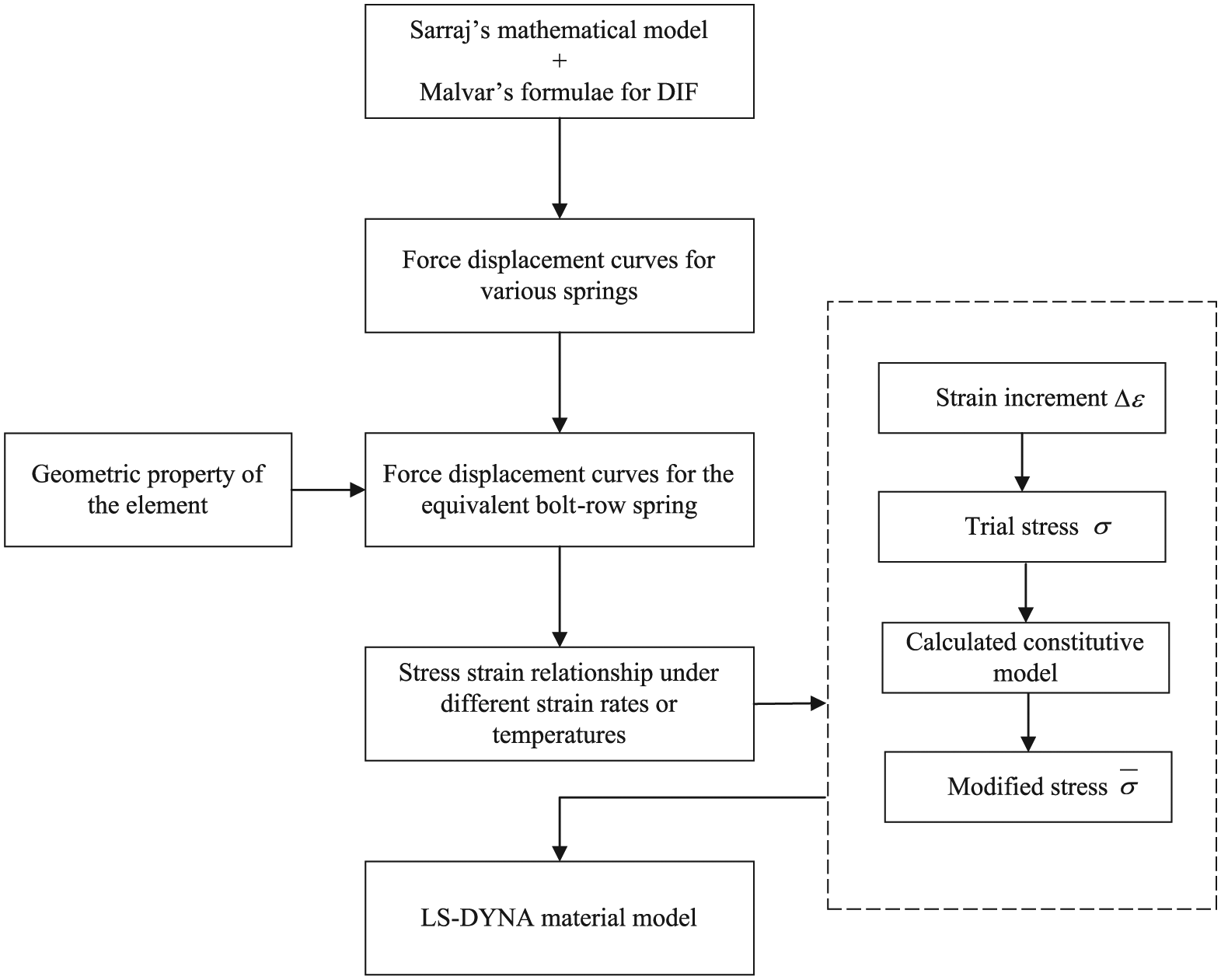
Stoddart et al. (2013) performed an experimental test on shear tab connections under blast using a purpose-built dynamic connection test facility. The test connection was connected to a fixed beam and a single load ram was used to load the connection. Yu et al. (2009) investigated the response of the shear tab connection in fire using an electric furnace. A typical connection was designed using three rows of bolts and placed in the middle of the furnace by a supporting beam. An inclined tensile force was applied to the beam end through the Macalloy bar. The above tests were used to validate the accuracy of the material model in predicting the connection behaviour under blast or fire. The beam, column, and connection of these tests were all modelled by beam elements in the numerical simulation. The elastic–plastic material model was used for beam column, whereas the compiled material model was used for connection. The force–rotation relationship from the compiled material model is compared to the blast test result in Figure 5(a), and the predicted dynamic behaviour of the connection in the figure agrees well with the experimental data. Figure 5(b) and (c) shows the comparisons of the connection behaviour calculated from the compiled material model against the fire test results at both the ambient temperature and 450°C. The response during the loading phase calculated from the compiled material model follows the results predicted by the test. Both the simulation and test predictions increase in the rotation stiffness when the beam end contacts the column flange. The maximum resistance is lower than the test value at ambient temperature, because the extra ductility provided by the higher bearing deformation of the upper bolt holes was not taken into account in the compiled material model (Yu et al., 2009). The maximum resistance is 15 kN higher than the test value at elevated temperature, which is due to the assumptions used in the compiled method.
Comparison of the results calculated from the material model and test: (a) strain rate and (b, c) elevated temperature.
The beams and columns of the steel frame were modelled using two-node fibre elements. A bilinear, elastic–plastic, stress–strain relationship with strain rate effect was used for beam and column elements in the blast analysis, whereas the stress–strain relationship and the thermal expansion coefficient of steel proposed by the EC3 code were used for beam and column elements in the fire analysis (ENV 1993-1-2, 2005). The radius cut RBSs were modelled with a beam element whose cross section was equal to the minimum cross section in the reduced section. The floor slabs were modelled using four-node shell elements, and composite action between the slab and beam was developed by rigidly connecting the shell and beam elements at the locations of the shear studs. To model the physical separation between the beam and floor slab, the shell elements were set above the beam elements based on the real distance. It was assumed the steel deck could only develop resistance along the directions of the flutes. Thus, the steel deck was modelled using steel bars attached directly to the shell elements, and the area of the steel bars was taken to be 50% of the area of the steel deck. The steel bar nodes were directly connected to the shell elements, which implied that no slippage between the steel deck and concrete slab was permitted. More detailed descriptions about the above modelling methods and material models were provided by Alashker et al. (2011). The schematic of this FE model is shown in Figure 6.
Finite element model of the steel frame.
To validate the accuracy of the numerical analytical model, an experimental program consisting of an isolated section of a small-span composite steel building was simulated. The construction details, connection types, and design loads can be found in Jahromi et al. (2012). The previously described modelling approach was adopted to establish the numerical model of the test. The floor was loaded with the same pattern as in the test by constantly increasing the carried load. A comparison of the force–displacement curve obtained from the numerical simulation against the experimental results is shown in Figure 7. The numerical result is in good agreement with the experimental result, because it accurately predicted the development of the force until the maximum vertical displacement was reached during the experiment. Because of the test setup restrictions, the load on the structure could only be increased to 780 kN, whereas the numerical model could simulate the whole process of structural response until the connection failed. The above validation illustrates that the proposed simplified model is capable of evaluating the progressive collapse potential of steel buildings under the combined hazard of blast and fire.
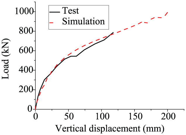
Comparison of the collapse resistance between the simulation and test.
Modelling the blast loads and fire actions
The effect of blast-induced damage on the fire resistance of steel structures is mainly determined by the internal blast load. The overpressure time history of the internal blast load is complex due to the repetitive shockwaves reflecting from the walls, ceiling, and floor. Unified Facilities Criteria (UFC) have adopted a simplified method for calculating the internal blast load, but the uniform distribution assumption and idealised pressure time history are inappropriate for reality and result in an inaccurate prediction of structural damage (Jonathon et al., 2013). The fluid–structure interaction (FSI) is widely regarded as an accurate method to simulate the blast load. However, the direct simulation method is very time-consuming, because it reproduces the whole process from the detonation of the explosive charge to the complete structural response. Thus, a relatively efficient and accurate method was employed in this article. In the first step, according to the mesh size used in the structural analysis, the beams and columns in AUTODYN were divided into several components to reflect the non-uniform distribution of internal blast loads on the members. The gauges were set in the middle of each component, and the blast load recorded by each gauge was used as a simplification to represent the average value of the blast load on the component; in the second step, the steel beams and columns were divided into several elements along the length direction, and each element was assigned with the blast load recorded by the corresponding gauge in the first step for structural analysis in LS-DYNA.
To model the internal blast load, the compartment was used as the object, instead of the overall frame, because the confined space limits the blast loads to leak. Therefore, only the loads acting on the members in the compartment need to be taken into account. The charge was detonated at 1.2 m above the ground, and the spherical blast wave propagated radially outwards from the detonation point. The blast wave was first modelled in one dimension, as shown in Figure 8(a), to reduce the computational cost and was then remapped to a 3D model, as shown in Figure 8(b), to simulate the interaction between the blast wave and members. A convergence analysis was conducted and the mesh size of 20 mm was used in the 3D model. Internal blast loads are composed of two stages: the shock non-stationary phase and the quasi-stationary phase. Due to the vulnerability of an infilled wall under blast (Wang et al., 2009), the compartment would behave like a fully vented space after the impact action of shockwave. Thus, only the shock stationary phase of overpressure time history was taken into account.
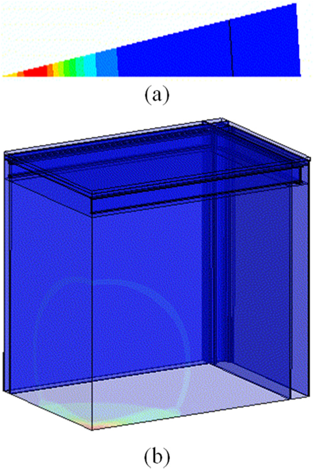
Blast wave propagation in the (a) one-dimensional and (b) three-dimensional models.
An example of the overpressure time history that acted on the column is shown in Figure 9(a). The two pressure peaks were formed due to the reflection of the Mach wave and the shockwave reflected from the wall. An example of the overpressure time history that acted on the beam is shown in Figure 9(b). The three pressure peaks were formed due to the refection of the original incident wave, the shockwave reflected from the ground, and the shockwave reflected from the wall. The quasi-stationary phases of the overpressure histories are neglected in Figure 9 to account for the failure of infilled walls.
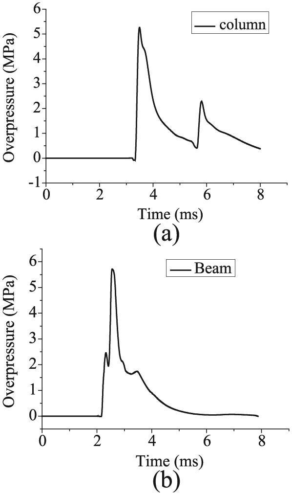
Typical overpressure time history on the (a) steel column and (b) steel beam.
The blast event results in damage to the automatic sprinkler system; thus, post-explosion fire has a high risk to be induced after the impact of the blast load. One of the important issues in fire analysis is the calculation of the temperature in the fire environment. The temperature of the air is correlated with many uncertainties, which make it complicated to determine the realistic temperatures in a fire environment. Therefore, the ISO834 standard temperature curve was adopted as a simplification to describe the time-dependent temperature of fire induced by an internal blast (ISO 834-1:1999, 1999). It was assumed that the fire would not spread horizontally or vertically; thus, only the members in the objective compartment were exposed to fire. Most of the fire protection materials are fragile and easily damaged by dynamic actions. Thus, the steel members in fire analysis were assumed to be unprotected, which leads to a conservative result. According to the theoretic approach proposed by Eurocode (ENV 1993-1-2, 2005), the temperature–time curves of steel members could be calculated by the following function
where Am/V is the section factor for unprotected steel members; Am and V are the exposed surface area and volume of the member per unit length, respectively; ca is the specific heat of steel;
An example of temperature–time curves for members in the gravity frame is shown in Figure 10. As shown, the temperature of a steel beam is very close to the atmospheric temperature when it is exposed to fire for more than 1 h, and the temperature of a steel column is lower than the beam. This can be explained according to the theoretic formula, the section factor is the key parameter to determine the temperature of unprotected steel members when the atmospheric temperature is the same. And the section factor of the beam is calculated as 249.7 m−1, while the section factor of the column is only 96.8 m−1. Therefore, the temperature of the steel column is lower than the beam due to the smaller section factor of the steel column.
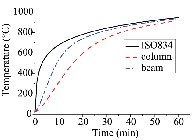
Temperature development of steel members under ISO834.
Progressive collapse analysis of a steel frame subjected to confined explosion and post-explosion fire
The progressive collapse analysis of three cases is discussed: (1) interior compartment, (2) peripheral compartment, and (3) corner compartment on the ground storey subjected to confined explosion and post-explosion fire. The collapse analysis in the fire only condition was also conducted as a comparison for further illustrating the progressive collapse mechanism of steel frames under the combined hazards. To easily describe the steel members, the beams and columns were marked based on Figure 1. For example, the column located at the intersection of axis A-6 is called A-6 column; the beam along axis 6 located between axes A and B is called AB-6 beam. In all cases, the compression and bending capacities of beam and column at ambient and elevated temperatures could be calculated based on formulae provided in AISC-360:2010 (2010).
Interior compartment case
As shown in Figure 1, the interior compartment was a part of the gravity frame. All gravity columns in the compartment were connected to the gravity beams with shear tab connections. The progressive collapse analysis in the fire only condition was conducted first for comparison. The temperature–time curves of the beams and columns were calculated based on the approach mentioned in section ‘Numerical model setup’. The connections were assigned with the same temperature–time curve as the corresponding beam. Previous research shows that most of the progressive collapse of steel frames is triggered by inelastic column buckling in fires (Porcari et al., 2015). Therefore, the buckling time of the heated column was defined as the progressive collapse time of the steel frame, and the occurrence of the progressive collapse was justified according to the vertical displacement–time curve at the top of the failed column.
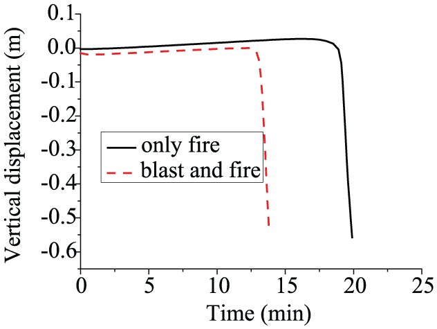
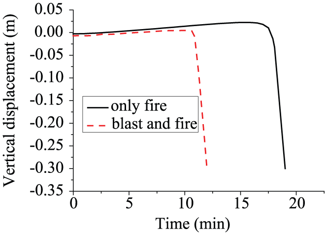
The analytical results indicate that the heated columns C-3, C-4, D-3, and D-4 (Figure 1) expand upwards during the initial phase of the fire. The axial loads carried by these columns increase as the temperatures rise due to the additional loads caused by restrained thermal expansion. At the same time, the stiffness of the steel members decreases at the elevated temperature, which eventually leads to the simultaneous buckling failure of the four columns. Vertical deformation at the top of a failed column is plotted against time in Figure 11. As can be seen, there is an initial expansion in the column and then a sudden fall after 16.5 min of the fire, illustrating the failure of the column. However, the fall is resisted after reaching a maximum displacement of approximately 1.2 m, and the progressive collapse does not occur due to the membrane action of the floor.

Vertical displacement at the top of a failed column.
After the connection failure in fire, the membrane action of the floor became the only mode of force transfer due to the non-continuity of the composite beam. The value of the tensile forces developed in the floor is shown in Figure 12. The figure only shows the tensile forces along the direction of the flutes, because the transfer of the tensile forces in the floor is mainly attributed to the steel deck and shrinkage reinforcement. However, the steel decks only accounted for resistance along the direction of the flutes, thus greater force in this direction is able to show the membrane action more obviously. The figure shows that the tensile forces become larger after the failure of the column and connection, which illustrates the contribution of membrane action of the floor to prevent the progressive collapse. The axial load values in columns are also examined to further illustrate the load redistribution mechanism of the floor. Taking the C-4 column as a representative, the axial load values in this column and neighbouring columns B-4 and C-5 against time are shown in Figure 13. The load carried by the failed column C-4 drops to a small value, whereas the load carried by the neighbouring column C-5 is bigger than column B-4. This result is in accord with Agarwal and Varma (2014) and can be explained by the above-mentioned reason.

Tensile force in the slab (kN): (a) before fire and (b) after fire.

Axial load values in different columns during fire.
The progressive collapse potential of the steel frame subjected to confined explosion and post-explosion fire was then evaluated. The charge weight was set to 216 kg, and the blast loads calculated from AUTODYN were written to LS-DYNA input files for structural analysis. Trial simulations showed that the composite floor would be destroyed under blast, causing the floor elements to be seriously distorted. If no element failure was set, the numerical simulation would terminate unexpectedly. However, due to the lack of the composite floor test under the blast load, it was difficult to determine the failure and erosion criterion of the floor element subjected to the confined explosion. For simplicity, it was assumed that the composite floor in the compartment failed completely under blast; thus, the floor elements were directly deleted from the model in the blast analysis. Although this simplification cannot fully reflect the realistic response of the composite floor under blast, it can be used to evaluate the effect of the non-continuity of floors triggered by blast loads on the progressive collapse potential of the overall structure and to predict a conservative result.
The results from the blast analysis indicate that the permanent displacement of the steel column in the weak-axis direction was larger than that in the strong-axis direction due to the lower moment capacity, as shown in Figure 14. Because of the restraint from the adjacent floors, the displacements of the steel beams were relatively small. Thus, most parts of the beams were still elastic. Furthermore, no connection failure was observed in the blast analysis. After the blast-induced response of the steel frame stabilised, the fire action was applied to analyse the progressive collapse potential of the damaged frame. It was assumed that the fire would not spread and the temperatures of the members were the same as in the fire only case. The analytical results show that the damaged steel columns expanded during the initial heating phase and failed by inelastic buckling approximately 13.5 min after the fire breakout, as shown in Figure 11. Compared with the fire only case, the buckling time was 3 min earlier because the blast-induced geometrical damage improved the load–displacement effect in the fire analysis. Similar to the fire only case, no failure occurred in connections until the heated column failed, indicating that the influence of the blast on the connections is negligible. After the failure of columns and connections, the membrane action of the floor was the only mechanism of force transfer. Figure 11 shows the vertical displacement–time curve at the top of the failed column under the combined hazard. As can be seen, the vertical displacement cannot be resisted after the column failure, which means the membrane action is unable to stop the progressive collapse under the combined hazard of blast and fire due to the non-continuity of floors triggered by blast loads.
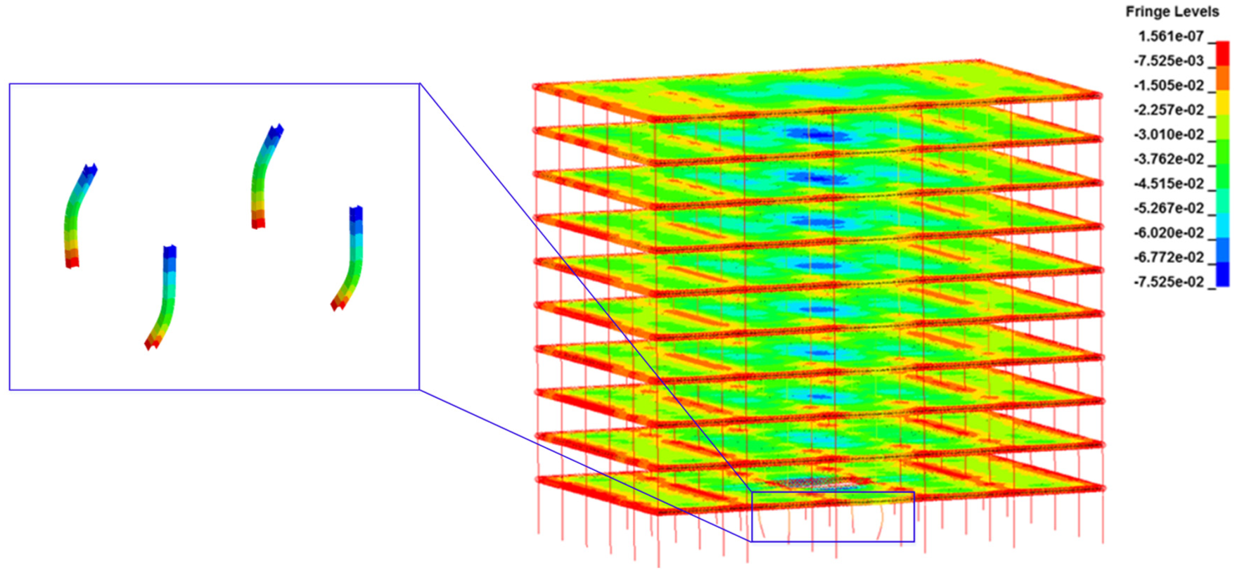
Deformed shape of the steel frame under blast.
Peripheral compartment case
As shown in Figure 1, the columns C-6 and D-6 were part of the moment resisting frames (MRFs), whereas the other columns, beams, and connections were part of gravity frames. Similar to the interior compartment case, the fire only analysis was conducted first. The analytical results indicate that the columns expanded and the load values in columns increased during the initial heating phase, as shown in Figure 15(a). The change in the load value in the perimeter column was larger than the gravity column due to the stronger restraint of MRFs. Unlike the simultaneous buckling failure in the interior cases, the gravity column C-5 failed by buckling first after 16 min of fire due to the higher loading ratio and smaller section. The axial loads redistributed immediately after the column failure, resulting in a sudden increase in axial load in column C-6. As the temperature increased further, column C-6 failed. Due to the weak boundary restraint conditions of the floor in the peripheral compartment, the membrane action could not stop the progressive collapse of the steel frame, as shown in Figure 16, which is different from the interior compartment case.

Axial load values in different columns under (a) fire only and (b) blast and fire.
Vertical displacement at the top of the gravity columns.
The progressive collapse potential of the steel frame subjected to confined explosion and post-explosion fire was then evaluated. The charge weight was set to 196 kg, and the assumptions used in the blast analysis were similar to the interior compartment case. Because of the larger loading face and lower moment capacity, the weak-axis permanent displacement of the perimeter column was the largest. Moreover, due to the weak restraint condition in the N-S direction of perimeter columns C-6 and D-6, the column tops displaced outwards under the blast, leading to the tensile failure of the shear tab connections at the south ends of beams 56-D and 56-C, as shown in Figure 17. After the failure of the connections, the south ends of the steel beams lost the restraint and started displacing downwards rapidly; however, because the displacement was arrested by the flexural composite action, no local failure occurred. In comparison, for the interior compartment case, no connections failed in the blast analysis due to the adequate restraint in both the N-S and W-E directions.

Deformed shape of the steel frame under blast load.
Then, the fire actions were applied to analyse the progressive collapse potential of the damaged frame. The analytical results show that although the displacement under blast is smaller, the gravity column still fails first due to the higher loading ratio. The failure time is 12.5 min, which is 3.5 min earlier than the fire only case, as shown in Figure 15(b). This difference is because the connection failure under blast increases the effective length of the column in fire, whereas the lateral displacement improves the load–displacement effect. However, the load redistributed to the column C-6 was larger than the fire only case because the damaged column C-5 failed earlier in fire, whereas the temperature of the perimeter column C-6 was still low and the load carrying capacity was still strong enough. Therefore, more loads could be redistributed to the column. As the temperature increased further, the perimeter columns failed approximately 16 min after the fire started. Due to the failure of the floor in the blast analysis and the weak boundary restraint conditions of the peripheral compartment, the progressive collapse could not be arrested by the membrane action of the floor, as shown in Figure 16.
Corner compartment case
As shown in Figure 1, except for column A-5, the other columns were all part of MRFs. Steel beam AB-6 is a part of MRFs and was connected to columns with RBS connections, whereas the other beams were connected to columns with shear tab connections. The fire only analysis was conducted first. The analytical results show that unlike the axial loads increase with temperature in the other cases, the axial load value in the corner column A-6 decreased in the heating phase, as shown in Figure 18(a). This decrease is because the corner column is a part of an MRF, where one more column is heated. If the west end of beam AB-6 is free to displace and rotate, a displacement demand at column B-6 leads to a larger displacement at the corner column location due to the continuity of the beam and moment connections. In practice, the displacement of corner column A-6 was the same as neighbouring column B-6, thus leading to an additional tension force in the corner column. Column B-5 failed after 16.5 min of fire, and the additional loads from the redistribution, in combination with the degradation of the material properties at the elevated temperature, resulted in the failure of the other columns, eventually leading to the progressive collapse of the steel frame due to the weak boundary restraint condition of the floors in the corner compartment, as shown in Figure 19.

Axial load values in four columns under (a) fire only and (b) blast and fire.
Vertical displacement at the top of the failed columns in MRFs.
Thereafter, the progressive collapse potential of the steel frame subjected to confined explosion and post-explosion fire was evaluated. The charge weight was set to 216 kg, and the above assumption was used in the blast analysis. The analytical results indicate that plastic strains and deformations were observed for the columns and beams in the compartment. The displacement of the gravity column was the largest due to the weak restraint condition at the top of the column, although the displacements of the columns in the MRFs were also large due to the large loading faces. Similar to the peripheral compartment case, because of large lateral displacements at the top of columns, connections at both ends of beam AB-5 and the south end of beam 56-B failed by tension. After the failure of the connections, the vertical displacement of beam 56-B was arrested by the flexural composite action. However, steel beam AB-5 detached from the supporting columns because both ends lost the restraint. Thus, one side of the neighbouring floor lost the restraint from the beam AB-5, leading to the occurrence of local collapse in the neighbouring compartment. This phenomenon was not observed in the interior and peripheral compartment cases, because no connection failure at both end of the beam occurred in these cases.
The fire analysis was then performed to analyse the progressive collapse potential of the damaged steel frame. The axial loads carried by four heated columns are plotted in Figure 18(b). The initial axial force in column B-5 was smaller than in the fire only case, because the blast-induced displacement caused the load to be redistributed to the neighbouring columns. The development of axial force values in four columns was similar to the fire only case, but the failure sequence changed due to the large lateral displacement of gravity column A-5 caused by the blast. Column B-5 still failed first after 10.0 min of fire, which was 6.5 min earlier than the fire only case. Due to the failure of neighbouring floors and the weak boundary restraint condition of the floors in the corner compartment, the progressive collapse of the steel frame occurred, as shown in Figure 19. It is worth mentioning that the connection at east end of beam AB-5 did not fail under blast when the charge weight was relatively small (e.g. 196 kg). However, the blast damage to this connection resulted in connection failure before column buckling in fire, leading to local collapse prior to the progressive collapse in the fire analysis. In comparison, for the other cases, the connections all failed after the buckling failure of columns (except for the failure under blast).
To investigate the effect of the interior MRFs on the progressive collapse resistance, the collapse analysis in the S-E corner compartment was conducted for comparison. Figure 20 shows the comparison of the collapse times between two corner compartments. Due to the smaller section, the failure time of the gravity column in the S-E corner compartment under fire only was 15.5 min, which is 1 min earlier than the S-W corner compartment case. However, when the compartment suffered combined hazard, the failure time of the column in the S-W corner compartment was earlier, because the larger loading face of the column in the interior MRF leads to a large lateral displacement under blast, whereas the moment capacity of the column in the weak-axis direction is lower. Both reasons make the column in the interior MRF more vulnerable in the post-explosion fire. The analytical result illustrates that the interior MRFs can improve the collapse resistance of the steel frame in fire but reduce the collapse resistance under the combined hazard of blast and fire.
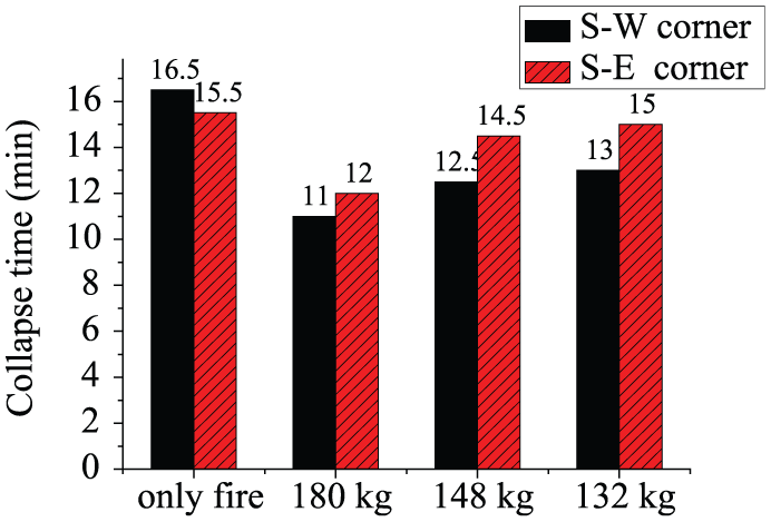
Comparison of the collapse times between two corner compartments.
Based on the analysis above, the following results are obtained: (1) progressive collapse is resisted by the membrane action of the floor. However, collapse occurs when the continuity of the floor is broken, as in the case of an interior compartment under combined hazard or when the restraint condition of the floor is weak, as in the cases of peripheral and corner compartments under fire or combined hazard. (2) The progressive collapse is initiated by gravity column failure in the interior and peripheral compartment cases. However, for the corner compartment case, the progressive collapse is initiated by failure of the column in the interior MRF. The collapse times under combined hazard are all earlier than the fire only cases. (3) There is no failure of the connection under blast in the interior compartment case, whereas the connection failure occurs under blast in the peripheral and corner compartment cases. The connection failure changes the effective lengths of columns, which promotes the column failure in fire or even leads to local collapse under blast. (4) For the interior and peripheral compartment cases, the connections fail after the buckling of columns in fire. However, for the corner compartment case, the blast damage to the connections may result in failure of the connections before column buckling, leading to local collapse prior to progressive collapse.
Influence of the charge weight on the collapse time
The influence of the charge weight on the progressive collapse time of the building was studied. The locations of the objective compartments were the same, and charge weights of 64, 77, 90, 110, 132, 148, 166, 180, 196, 216, 232, and 250 kg were used to calculate the collapse time of steel frames subjected to confined explosion and post-explosion fire.
Interaction curves showing the collapse time and charge weight are plotted in Figure 21. For the interior compartment case, the abscissa axis starts at 64 kg because no collapse occurs in the fire only case. There is no decrease in collapse time when the charge weight is increased up to 132 kg. When the charge weight increases from 132 to 250 kg, the collapse time is decreased from tmax to 0.576tmax (tmax is the collapse time at 64 kg).
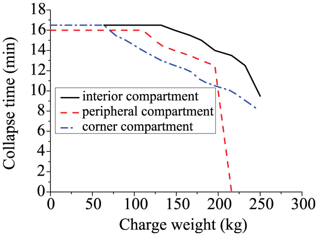
Interaction curves between the collapse time and the charge weight.
For the peripheral compartment cases, the collapse times are the same as the fire only case until the charge weight reaches 110 kg. When the charge weight increases from 110 to 196 kg, the collapse time is decreased from tmax to 0.719tmax (tmax is the collapse time in the fire only case). When the charge weight reaches 216 kg, the collapse time of the steel frame is decreased to 0 min, which means progressive collapse occurs in the blast analysis.
For the corner compartment cases, the collapse times are the same as the fire only case until the charge weight reaches 64 kg, and the times subsequently decrease to 0.485tmax (tmax is the collapse time in the fire only case) when the charge weight increases to 250 kg. There is no progressive collapse observed in the blast analysis under the employed charge weights. Furthermore, Figure 21 shows that the collapse time of the peripheral compartment case is the earliest when the charge weight is small. As the charge weight increases, the collapse time of the corner compartment case becomes the earliest.
The above analytical results lead to the conclusions that gravity columns and columns in the interior MRF are key components in the progressive collapse assessment under combined hazard. The blast not only results in geometrical damage to the structural members, improving the load–displacement effect, but also leads to the failure of the shear tab connections and constructional measures. The failure of the shear tab connection reduces the fire resistance of the steel frame; therefore, providing more robustness to the shear tab connection can potentially improve the collapse resistance of the steel frame and prevent local collapse prior to progressive collapse. Furthermore, the existence of interior MRFs slightly improves the fire resistance of the steel frame in the fire only condition, whereas it obviously reduces the fire resistance under the combined hazard of blast and fire. Taking all of the threats into account, the layout of MRFs along the exterior frame is suggested. For the overall frame, the peripheral compartment is the weakest area in the fire only case. However, the weakest area changes to the corner compartment under the combined hazard, which indicates that the effect of a blast on the corner compartment is more serious.
Because the composite beam cannot behave in continuity after failure of the connection, the membrane action of the floor is the only mode of force transfer in fire. However, the original designed concrete slab, with wire 1.4 in a 152 × 152 mm grid spacing, is unable to transfer the loads carried by failed columns to neighbouring columns, leading to the occurrence of progressive collapse in almost all cases. To prevent the progressive collapse, the floor should be reinforced with sufficient alternate load paths to redistribute loads, which will be discussed in the next section.
Assessment of the collapse potential with enhanced floor
The above analysis highlighted the contribution of the shrinkage reinforcement and steel deck in transferring loads. Thus, to prevent the progressive collapse of the overall building, enhanced floors with increased welded wire reinforcement areas and steel deck thicknesses were adopted. The welded wire reinforcement adopted the standard wire size, and the grid spacing was 152 mm by 152 mm in all cases. The combined hazard scenarios in the peripheral and corner compartment were used for analysis due to the weaker collapse resistances in these cases. Figure 22 shows the vertical displacements at the top of the typical columns in the peripheral and corner compartments with different enhanced floors. For the peripheral compartment, the steel frame can sustain stability under the combined hazard of blast and fire until the weld wire size reaches W12 (Aw = 78.5 mm2), while the steel deck thickness increases to 1.52 mm, which is the maximum standard thickness.
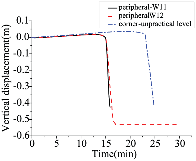
Vertical displacements at the top of the typical columns for the enhanced floor cases.
However, for the corner compartment, because the restraint of the floor was not guaranteed in both the N-S and W-E directions, the contribution of the floor system to the collapse resistance was almost negligible; thus, the progressive collapse could not be prevented by increasing the reinforcement ratio and steel deck thickness in the floor. To prevent the progressive collapse triggered by the failure of columns in the corner compartment, protection recommendations were proposed: the columns in the corner compartment could be encased in concrete, preventing the exposure of the columns to fire after the impact of the blast load, and the steel in the corner compartment could be changed to fire-resistant steel, whose yield strength at elevated temperature is much larger than that of conventional steel.
The above conclusions are based on the analysis where the triggering loads occur on the ground floor. However, progressive collapse has a higher risk to be initiated when the triggering loads occur in the upper floors because fewer floors participate in absorbing the released energy and because of the weaker collapse resistance provided by the smaller sections of steel beams in the upper floors. Due to the uncertainty of the location where the triggering loads occur, the proposed recommendations for corner compartment should be used in all stories, whereas the larger reinforcement ratio should be used in the upper floors. Furthermore, the nonlinear numerical analysis can be used as a aid in building design to insure the stability of structures and to adjust the reinforcement ratio if collapse occurs. The analysis in this article did not account for situations where the fire spreads horizontally or vertically beyond the objective compartment. These situations will result in extension of the areas where the progressive collapse occurs and should be analysed in further studies.
Conclusion
This article proposes an accurate analytical model to evaluate the progressive collapse potential of steel frames subjected to confined explosion and post-explosion fire. The macro-model for shear tab connection is established, and a material model that can reproduce the nonlinear dynamic behaviour of connections under the combined hazard of blast and fire is compiled as subroutines. The FE package AUTODYN was employed to simulate the real internal blast loads to accurately reflect the effect of the blast. Numerical simulations in LS-DYNA were conducted to investigate the progressive collapse mechanism of steel structures under the combined hazard. The following conclusions can be drawn from the analysis:
The gravity columns are most likely to reach the buckling failure first and play an important role in the structural stability. However, the existence of the interior MRF causes the columns in the MRF to be the weakest link of the building under the combined hazard condition. Thus, the MRFs are suggested to be set along the exterior frames.
The shear tab connection is an important component in the progressive collapse assessment. The failure of the connection under blast promotes column failure in fire or even leads to local collapse under blast. Furthermore, blast damage to the connection may result in the connection failure before column buckling in fire, leading to local collapse prior to the progressive collapse of the building. Thus, inducing greater robustness in the shear tab connections can improve the progressive collapse resistance of the building.
Due to the initial blast damage to the steel members and connections, the progressive collapse time under the combined hazard is earlier than the fire only case. Moreover, the progressive collapse time remains the same until the charge weight reaches a critical value and then decreases as the charge weight increases further. The weakest area for the steel building is the peripheral compartment for the fire only cases but changes to the corner compartment for the combined hazard cases, which indicates that the effect of a blast on a corner compartment is more serious.
After column failure in fire, the membrane action of the floor becomes the only mode to redistribute loads. However, the membrane action may not work when the restraint condition of the floor is weak or the continuity of the floor is broken. Due to the small reinforcement ratio in the original designed floor, the membrane action is unable to prevent the progressive collapse of the overall building in almost all cases. Thus, enhanced floors with increased welded wire reinforcement areas and steel deck thicknesses are used to prevent progressive collapse, except for the corner compartment case. The columns in the corner compartment should be encased in concrete or the steel used in the corner compartments should be changed to fire-resistant steel in the design of future buildings.
Footnotes
Declaration of Conflicting Interests
The author(s) declared no potential conflicts of interest with respect to the research, authorship, and/or publication of this article.
Funding
The author(s) disclosed receipt of the following financial support for the research, authorship, and/or publication of this article: The authors wish to acknowledge the financial supports from the National Natural Science Foundation of China (Nos 51178306 and 51238007), the Natural Science Foundation of Tianjin (No. 13JCZDJC35200) and the National Key Technologies R&D Program of China (No. 2012BAJ07B05).