
Abstract
It is always a challenge to efficiently and accurately estimate the force on structures from falling objects. This study aims to predict the maximum impact force on reinforced concrete beams subjected to drop-weight impact using artificial neural network. A new empirical model including a comprehensive version and a simplified version is proposed to estimate the maximum impact force. The model was verified against a database collected from the literature including 67 reinforced concrete beams tested under drop-weight impacts. The database covers the concrete strengths ranging from 23 to 47 MPa, the projectile mass from 150 to 500 kg, and the impact velocity up to 9.3 m/s. The prediction of the comprehensive version of the proposed model fits the experimental results very well with an average absolute error of 11.6%. The simplified version of the proposed model is established for easy estimation, with the average error of 23.2% in prediction of the maximum impact force.
Keywords
Introduction
Design of structures against impact loads is always a challenge for structural engineers but often cannot be avoided because many structures in their service life are exposed to potential impact loads. For example, bridge columns, low story columns in buildings, and roadside structures such as guardrails and traffic signal structures are the most vulnerable to vehicle impacts (El-Tawil et al., 2005; Tsang and Lam, 2008); bridge piers in inland waterways and offshore structures might be subjected to ship impacts; and structures in mountainous areas are exposed to rock-fall impacts. Under impact loads, the structural responses and failure modes are very different from those under static loads. The economic cost due to the damage of these structures, which results in rerouting in cases of bridges, repairing, and rebuilding of the structures, could be enormous. They might also cause the loss of invaluable human life. Therefore, proper design, protection, and strengthening of these structures against impact loads are crucial. To achieve these, being able to reliably predict the impact loads is essential.
Previous studies have shown that the impact force is significantly higher than the reaction force in reinforced concrete (RC) beams subjected to impact loads (Kishi et al., 2002; Kishi and Mikami, 2012; Saatci and Vecchio, 2009). It is different from static loading scenarios in which either the maximum applied loads or the reaction forces can be used to estimate the resultant bending moment and shear force in an RC beam. When a beam is subjected to an impact load, the force is not necessarily completely resisted by the reaction force. In fact, if the impact loading is very fast, the peak impact force could be completely resisted by the inertial resistance of the beam. In such cases, the peak dynamic bending moment and shear force in the beam depend on the peak impact force and the corresponding inertial resistance from the impacted beam (Cotsovos, 2010; Saatci and Vecchio, 2009). The measured reaction forces at the beam supports, therefore, cannot be used to estimate the impact force as in the case of static equilibrium and cannot be used to estimate the peak dynamic bending moment and shear force the beam experienced during impact. The resulting bending moment and shear force diagrams can be built if the impact force and inertia force are known. The inertia force can be estimated from the equilibrium equation with an assumption that the impact force is resisted by the inertia force. To this end, the diagrams can be built with a known impact force (Cotsovos, 2010; Pham and Hao, 2016; Saatci and Vecchio, 2009). Unfortunately, there has been no study about predicting impact force of RC beams.
This study thus aims to predict the impact force of RC beams under impact loads. There are, in general, three approaches to predict the impact force on a structure, namely, dynamic response analysis of an equivalent single-degree-of-freedom (SDOF) system, analytical approach based on various contact laws, and analytical approach based on conservation of energy. As will be briefly reviewed in this article, applications of all these approaches are not necessarily straightforward, and their accuracies depend on some assumptions such as the deformation and damage of the impacted structure and interaction between the impactor and the structure. In this article, a brief review on dynamic behavior and models for RC beams against impact loads is presented. Two new empirical models are proposed to calculate the maximum impact force on RC beams under drop-weight tests. The first one is based on artificial neural network (ANN) and available testing data, while another one used a simplified ANN using a simpler transfer function. Both models give reasonable predictions of impact forces on RC beams and can be used in design and analysis of RC beams subjected to falling objects.
Dynamic response of RC beams under impact loads
When a drop-weight impacts a beam and accelerates it, the equilibrium is achieved by the participation of all the force elements including impact force, reaction force, and inertial force. The impact event is very fast so that viscous damping force is very small and can be neglected. The acceleration of the beam results in inertial resistances to the impact force in which their magnitudes can be estimated by multiplying the mass and acceleration along the beam. The direction of these inertial forces is opposite to the direction of the accelerations. It is noted that the impact force and the reaction forces are point loads while the inertial forces distribute throughout the body of the beam. The distribution of the inertial forces will be discussed and presented in the following section. At any time during an impact event, the equilibrium of a beam is always maintained by the impact force, inertial forces, and reaction forces as shown in Figure 1. In this figure, P(t) is the impact force, R(t) is the reaction force, a(t) is the acceleration of the beam, ρa(x, t) is the distributed inertial force, and ρ is the beam mass density per unit length. This balance condition of an RC beam is confirmed by experimental results from the study by Saatci and Vecchio (2009). These authors conducted an experimental study on eight RC beams tested under a drop-weight system. The beams were 250 mm in width, 410 mm in height, and 4880 mm in length (3000 mm span). The experimental results showed that the maximum impact force was almost entirely resisted by the inertial forces, and the reaction force was very small as compared to the impact force. This observation was also experimentally confirmed in other studies (Bhatti et al., 2009; Cotsovos, 2010; Kishi et al., 2002). It is worth noting that the maximum impact forces in all these tests were significantly higher than the reaction forces, indicating the significant inertial resistance of the beams against impact loads. Therefore, the resultant peak moment and shear force, which are critical for the design of beams, cannot be accurately estimated by considering the reaction force alone, as practiced in the equivalent static analysis.
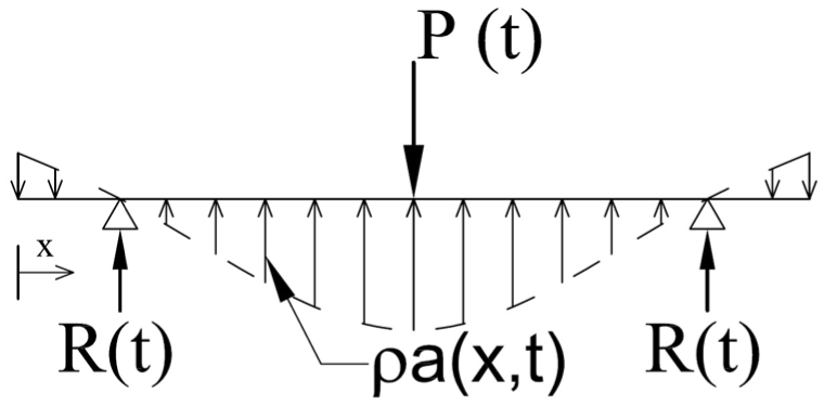
Dynamic free diagram for an RC beam under impact loads.
In order to investigate the distribution of the inertial forces along a beam, Bentur et al. (1986) conducted an experimental study on concrete beams including RC and plain concrete. The beams which were 100 × 125 mm2 in cross section and 1400 mm long were tested under 345-kg steel projectile dropping at a height up to 3 m. During the experimental study, some accelerometers were attached to the beams to monitor the acceleration of a few critical points on the beams and thus the distribution of the inertial forces. The experimental results showed that the distribution of accelerations along the concrete beams was essentially linear. However, the distribution of accelerations along the RC beams was observed to be sinusoidal. This observation was also confirmed by Banthia et al. (1989). These observations indicate that reinforcements in the concrete beam change the distribution shape of inertial resistance. Adding reinforcements does not significantly change the mass density and flexural stiffness of the beam but affects stress wave propagation in the beam owing to the interaction of stress wave with reinforcement bars. The change in inertial force distribution is believed to be related to the stress wave propagation. However, more studies are needed to better understand inertial force resistance in a structure subjected to an impact load. Despite reinforcements affect inertial force distribution, it was found that the acceleration distribution was insensitive to the impact behavior (Bentur et al., 1986). For simplicity, the distribution of the inertial forces is usually assumed to be linear as shown in Figure 2. As a result, the resultant peak dynamic moment and shear force can be estimated from the impact force. It is noted that at the time as the maximum impact force occurred, the reaction force is usually zero or very small, which can be neglected, and thus, the impact force is balanced by the sum of the inertial forces. Figure 2 shows the distributions of the resultant bending moment and shear force in an RC beam corresponding to the maximum impact force.
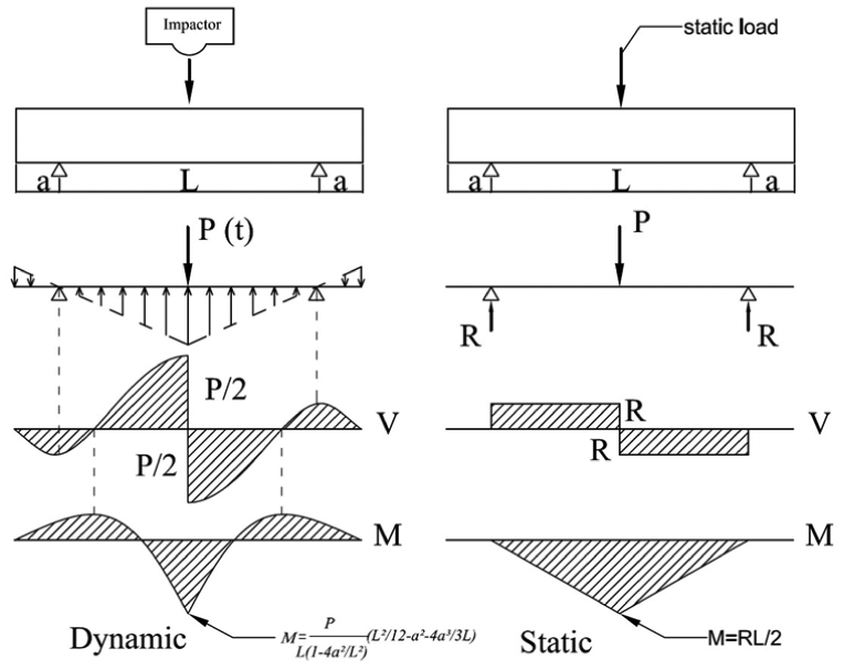
Resultant moment and shear force at the maximum impact force.
Previous studies reported that RC beams failed statically in the pure flexure mode may shift to the shear failure mode in impact tests (Magnusson et al., 2010a, 2010b; Micallef et al., 2014; Ožbolt and Sharma, 2011; Saatci and Vecchio, 2009). Hughes and Beeby (1982) pointed out that shear failure may occur in RC beams due to activation of higher modes of vibration under impact loads. In addition, Ožbolt and Sharma (2011) suggested that under impact loads (velocity around 1 m/s), shear reinforcement has not been activated yet, and thus, the dynamic response is not similar to that in static loads. Saatci and Vecchio (2009) experimentally proved this phenomenon and explained the formation of the shear-plug in impact tests. Moreover, it can be seen from Figure 2 that the shear force is equal to half of the impact load, while it is equal to reaction force in static tests. Considering the peak impact force P and performing static equilibrium analysis, the largest shear force equals to P/2 in both the cases as shown in Figure 2, but the peak dynamic bending moment is equal to PL/12 if overhang a is assumed to be zero, which is three times smaller than that obtained in the static case. Therefore, a beam that experiences flexural damage under static loading might suffer shear damage under impact load. As mentioned previously, experimental results depicted that the peak impact force a beam can resist is significantly greater than the reaction force recorded in impact tests. As a result, it is important to accurately estimate the impact forces for reliably predicting the peak dynamic shear force in the beam for designs to prevent brittle shear failure of the beam.
In brief, the shear failure is likely critical in the case of impact loads. The peak dynamic shear force in impacted beams needs to be estimated from the maximum impact loads. Therefore, prediction of the impact force is essential, and it attracts many attentions from the research community. A brief review of the current approaches for predicting the impact loads on structures is presented in the following.
Existing analytical models
Current approaches for predicting the impact forces are mainly proposed for those on concrete panels or composite plates (Abrate, 2001; Delfosse and Poursartip, 1997; Foo et al., 2011; Hazizan and Cantwell, 2003; Lifshitz et al., 1995; Olsson, 2001, 2002; Shivakumar et al., 1985; Zhou and Stronge, 2006). There are, in general, three approaches to predict impact loads on structures, including spring–mass model, contact law, and energy-based approach. The spring–mass models are divided into two common types consisting of either an SDOF or a 2-DOF model. The 2-DOF spring–mass model has one spring representing the linear stiffness of the structure (k2), another spring representing the local indentation (k1), the mass of the projectile (M), and the effective mass of the structure (m) as shown in Figure 3. It is noted that the stiffness of the structure can be determined to account for either or both shear and bending deformation. From the free body diagram of the system, the equations of motion can be written as (Abrate, 2001)


Spring–mass models: (a) 2-degree-of-freedom model and (b) single-degree-of-freedom model.
It is noted that the impact force from the above equation can be estimated as P = k1(x1 − x2). Abrate (2001) presented a solution to solve the above equations and thus the impact force. Moreover, Abrate (2001) also provided solutions for the SDOF spring–mass model for two scenarios. In the first instance, the overall deflection of the structure is neglected as compared to the local indentation. In such cases, the spring in Figure 3 represents the contact stiffness, and the equation of motion can be written as

The second scenario neglects the local indentation but includes only the deflection of the structure. The equation of motion of the corresponding SDOF model is

where kb is the stiffness of the structure representing the bending flexural and km is the stiffness of the structure accounting for the membrane effect. All the above equations require iterative solutions which are not straightforward, and no such models have been calibrated for RC beams yet. Moreover, it is not straightforward to determine the various parameters in a real impact case. For example, the stiffness of the beam deformation and indentation are not necessarily constants under large impact loads. They do not depend only on the structural dimensions and material properties but also strongly depend on the interaction between impactor and beam and amplitude of impact loads and structural deformation.
The impact force (P) can also be predicted using the contact law as follows (Abrate, 2001)

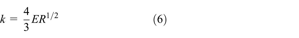
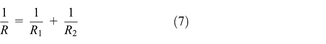
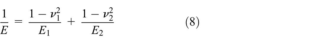
where k is the contact stiffness; α is the indentation; R1 and R2 are the radii of curvature of the two objects; and E1 and E2, and ν1 and ν2 are Young’s moduli and Poisson’s ratios of the two objects, respectively. This contact law model is based on the contact model proposed by Hazizan and Cantwell (2003), which can be written as

where k and n are constants which are determined by fitting the experimental results to this relationship. Again, the accuracy of this model depends on the accuracy of various parameters. Determination of some of them such as the contact stiffness and indentation in practice is not straightforward. It is worth noting that the above model was proposed for an impact event between two objects which have curved surfaces. However, the surface of RC beams and the projectile in most of the cases is flat. For such cases, the value of R in equation (7) becomes infinite, and thus, this model is inapplicable for predicting the impact force on RC beams.
In addition, the energy-balance model is another commonly used approach to predict impact force (Abrate, 2001; Foo et al., 2011; Hazizan and Cantwell, 2003; Zhou and Stronge, 2006). It is well known that the initial kinetic energy of the projectile causes deformation of the structure during the impact event. Assuming that when the structure reaches its maximum deflection, the velocity of the projectile becomes zero, and all initial kinetic energy is transferred to deform the structure. Accordingly, the energy-balance equation can be written as
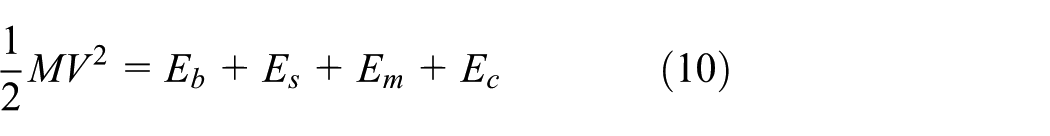
where V is the initial velocity of the projectile and Eb, Es, Em, and Ec are energies representing the bending deformation, shear deformation, membrane component, and indentation effect, respectively.
Hazizan and Cantwell (2003) neglected membrane effect and solved the above equation without Em. Abrate (2005) provided a solution for the above energy-balance equation as follows
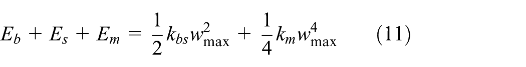
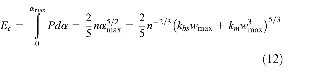
where kbs is the linear stiffness including bending and transverse shear deformation effects, km is the membrane stiffness, and wmax is the maximum deflection at the impact point. The energy stored in the contact region can be written as
Substituting equations (11) and (12) into equation (10), the energy-balance equation becomes
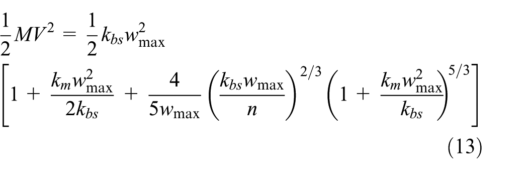
If the membrane effects are neglected (km = 0), the above expression can be simplified as (Abrate, 2005)
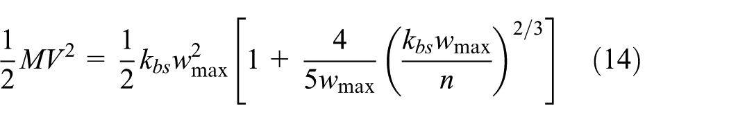
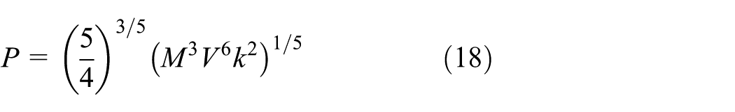
The above equation can be written in terms of the maximum impact force
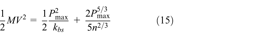
In the cases of steel projectile impacting RC beams, the local deformation in the contact zone can be negligible as compared to the overall deflection, which means that the second term of the right-hand side of the above equation can be ignored. The impact force can then be estimated by the following equation

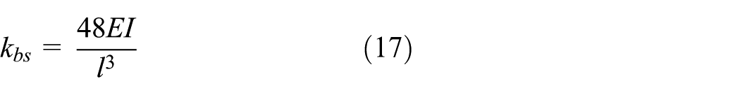
Equation (16) can be used to predict the impact force if the linear stiffness of RC beams is estimated. However, the linear stiffness of a structure does not necessarily remain constant during the impact and is not able to be simply estimated. For simplicity, regardless of the shear effects, the linear stiffness of RC beams can be estimated in terms of the bending stiffness
However, if the deformation of the structure is negligible, the kinetic energy of the projectile is equal to the energy stored in the contact region. From equation (15), the first term of the right-hand side of the equation is neglected, and the impact force can be calculated as
where k can be estimated from equation (6).
In general, the above models can be adopted and applied to predict impact force on RC beams. However, as discussed above, the application of these approaches is not straightforward and sometimes not possible. To overcome these problems, this study collects available data of RC beams under impact loads and proposes new models to predict the maximum impact force.
Database
Data used for the development of empirical model were collected from other studies in the literature. Since there are many types of impact tests, this study limits to the data from drop-weight tests on RC beams, in which RC beams were impacted by dropping a steel projectile from a certain height. RC beams considered in this study are conventional RC beams with a rectangular section. There are a few studies about concrete filled circular steel tubes which are not in the scope of this study. Moment of inertia is one of the important parameters in the proposed model so that geometry of the section and reinforcements and mechanical properties of materials are required in this study. Studies which do not meet these requirements are excluded from this database. In addition, when the modulus of concrete was not specified, it was estimated using the following equation
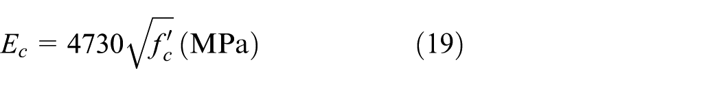
where Ec is the concrete modulus and
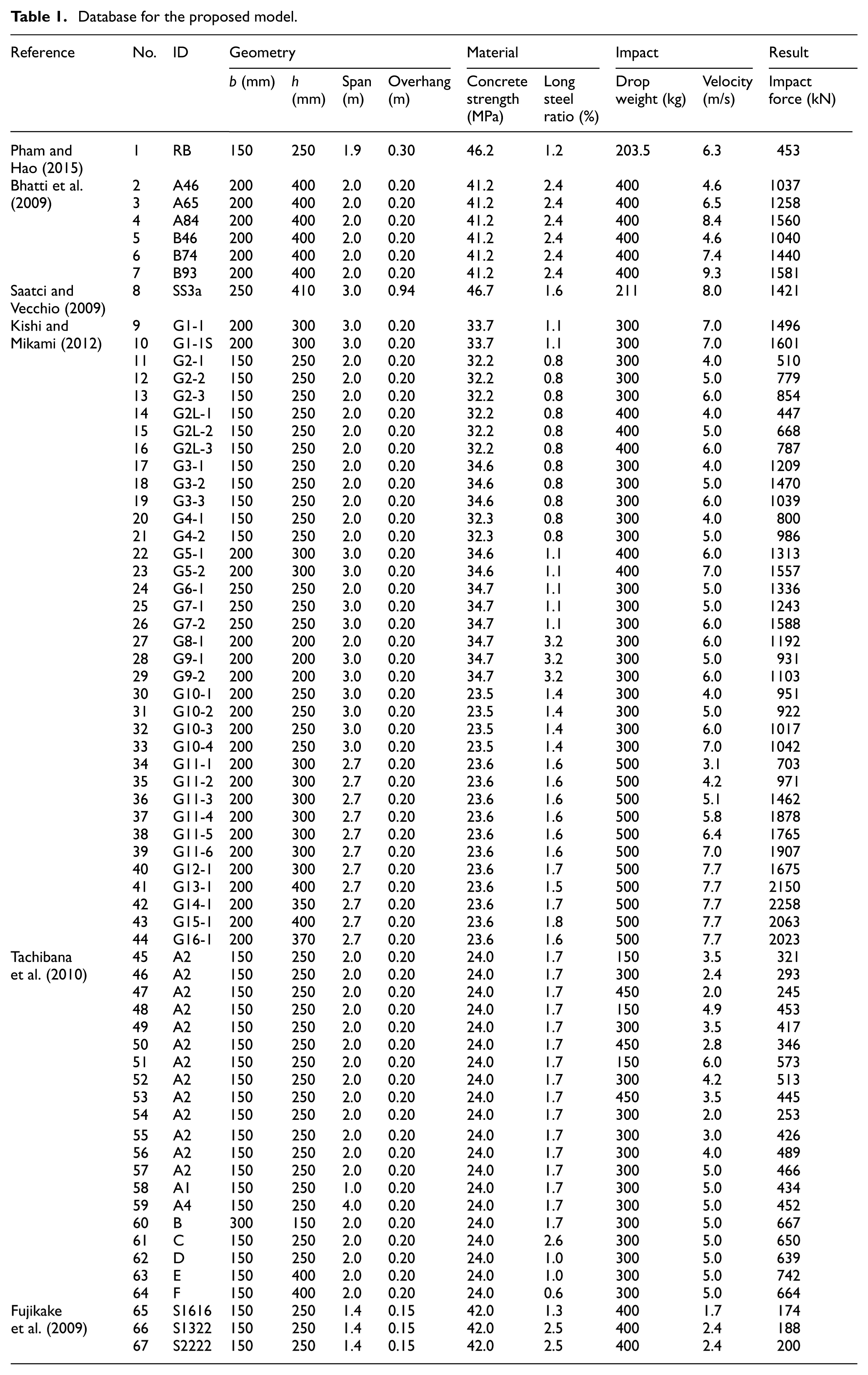
A significant number of tests have been carried out to investigate the behavior of RC beams against impact loads (Adhikary et al., 2015; Bhatti et al., 2009; Fujikake, 2014; Fujikake et al., 2009; Kishi et al., 2002; Kishi and Mikami, 2012; Saatci and Vecchio, 2009; Somraj et al., 2013; Tachibana et al., 2010). If the compressive strength of concrete was average from cube specimens, it will be converted to the compressive strength of standard cylinders with a factor of 1.2 (Mansur and Islam, 2002). A total of 120 specimens were reported in the above studies, but some of the studies did not provide values of the impact force (Adhikary et al., 2015). Before adopting the testing results in the database for developing the ANN predictive model, the results are examined carefully. Some peculiar results, which are those obtained from very similar testing conditions but have very different impact forces, are excluded. The exact reason for why those results reported in various articles are so different is unclear. However, possible measurement noises, fluctuation of testing conditions, and even malfunctioning of the measurement equipment could attribute to those results. Since their reliability is in doubt, they are not included in the current database. Finally, the database consists of 67 RC beams tested against impact loads, as presented in Table 1.
Database for the proposed model.
Development of a new model for predictions of impact load
ANNs
The impact behavior of RC beams under drop-weight tests is complex in which the relationship between the impact force and other variables is highly nonlinear. A lot of efforts have been spent in order to establish a dynamic model for the impact behavior under impact tests, but this problem has not been well solved. There are still many issues for this problem, such as it is difficult and requires sophisticated equipment to accurately measure the impact forces in such tests, the failure mechanism and the stress propagation in the beams have not been well documented, effect of the distributed inertial forces of the beams and inertial force of the test apparatus, and other uncertainties have not been well understood. Meanwhile, such type of problem is able to be solved by some mathematical methodologies in the field of machine learning, for example, ANN or support vector machine. Among these methods, ANNs have been used to solve some sophisticated problems in the field of civil engineering and provided excellent results. ANN has been applied to many areas, including optimization (Hadi, 2003; Kim et al., 2006), identification and control (Chen et al., 1995; Masri et al., 1992), damage detection (Elkordy et al., 1993; Wu et al., 1992), structural analysis and design (Adeli and Park, 1995; Hajela and Berke, 1991), shear resistance of beams strengthened with fiber-reinforced polymer (FRP; Perera et al., 2010a, 2010b), and compressive strength of FRP-confined concrete (Jalal and Ramezanianpour, 2012; Naderpour et al., 2010; Pham and Hadi, 2014a, 2014b).
Architecture of the ANN models
The impact force model was developed using the ANN toolbox of MATLAB R2015a (MATLAB, n.d.) in order to estimate the maximum impact force of RC beams under drop-weight tests. The database was collected from the literature including 67 specimens. The database was randomly divided into three subdatabases for training (70%), validation (15%), and test (15%) by the function “Dividerand.”
Following the data division and preprocessing, the optimum model architecture, including the number of hidden layers and the corresponding number of hidden nodes, is achieved by trial-and-error method. Hornik et al. (1989) recommended that multilayer feedforward networks with as few as one hidden layer of neurons are capable of universal approximation in a very precise and satisfactory sense. Accordingly, one hidden layer was used in this study. The optimal number of hidden nodes was obtained by a trial-and-error approach in which the network was trained with a set of random initial weights and a fixed learning rate of 0.01.
Once the numbers of input, hidden, and output neurons are determined, it is possible to estimate an appropriate number of samples in the training dataset. Upadhyaya and Eryurek (1992) proposed an equation to calculate the necessary number of training samples as follows
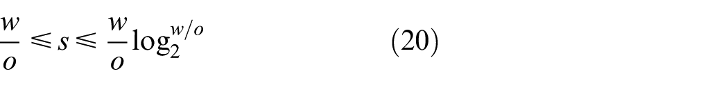
where w is the number of weights, o is the number of the output parameters, and s is the number of the training samples. The proposed model has six inputs (neurons), five neurons in the hidden layer, and one output, which are clearly explained in the following section. Substituting the number of weights and the number of the output parameters into equation (20), the above condition is achieved

As can be seen from equation (21), the sufficient number of specimens has been used for the training process. Once the network has been designed and the input and output have been normalized, the network would be trained. The MATLAB neural network toolbox supports a variety of learning algorithms, including gradient descent methods, conjugate gradient methods, the Levenberg–Marquardt (LM) algorithm (adopted in this study), and the resilient backpropagation algorithm. In the MATLAB neural network toolbox, the LM method (denoted by function “Trainlm”) requires more memory than other methods. However, the LM method is highly recommended because it is often the fastest backpropagation algorithm in the toolbox. In addition, it does not cause any memory problem with the small training dataset although the learning process was performed on a conventional computer.
In brief, the network parameters include the following: network type is feedforward backpropagation, number of input layer neurons is 6, number of hidden layer neurons is 5, one neuron of output layer is used, type of backpropagation is LM, training function is “Trainlm,” adaption learning function is “Learngdm,” performance function is mean square error (MSE), and transfer functions in both hidden and output layers are “Tansig.” The network architecture of the proposed model is illustrated in Figure 4.
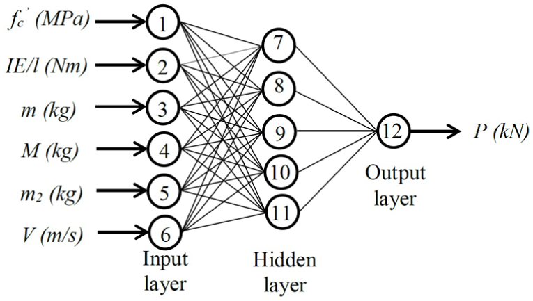
Architecture of the comprehensive version of the proposed model.
Proposed model
As previously mentioned, the impact force is governed by the flexural stiffness of RC beams (spring–mass models), weights of the beams and the projectile, and impact velocity of the projectile (as mentioned in conservation of momentum models). Accordingly, the proposed model includes six input parameters: the compressive strength (
The performance of the proposed model is verified against the experimental results of 67 RC beams under drop-weight tests. Figure 5(a) shows the prediction of the proposed model as compared to the experimental values. It is noted that the proposed model is an optimal network architecture after many trials of different numbers of hidden layers and neurons. The proposed model can predict the impact load with an error of about 11.6%. The best-fit line almost aligns with the 45° benchmark proving a strong correlation between the experimental results and the predictions. The correlation factor of these two variables is R2 = 0.95. In addition to the verification of the proposed model, the energy-balance model (equation (16)) is plotted against the database as shown in Figure 5(b). As can be seen, the predictions from equation (16) do not fit the experimental results well. The average absolute error (AAE) of the predictions from equation (16) is 51%. This comparison demonstrates that the proposed model outperformances the current commonly used model defined by equation (16).
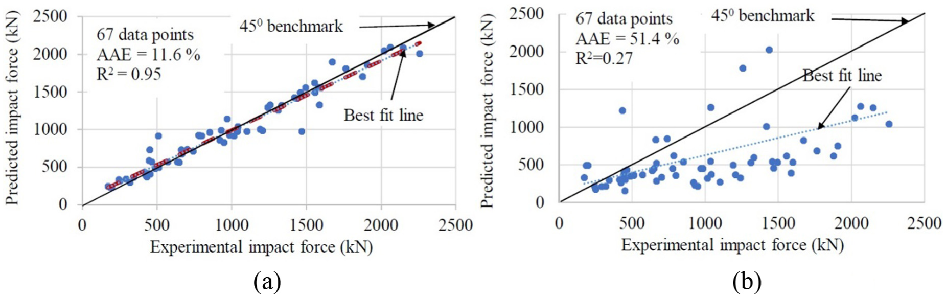
Verification of the comprehensive version of the proposed model: (a) proposed model and (b) energy-balance model (equation (16)).
It is worth noting that since the proposed ANN model has been trained, it is ready to be adopted for predicting the impact force. However, to be able to use the proposed ANN model, users need to have fundamental knowledge about the neural network algorithm. To make the proposed model for direct application without performing ANN analysis, a trained ANN was simulated by MS Excel. By following the below steps, the MS Excel file has been built and can be used without understanding about ANN. Details of this method and the normalization functions could be found elsewhere in the study by Pham and Hadi (2014b):
Step 1. Normalize the inputs to fall in the interval [−1, 1];
Step 2. Calculate the proportional matrix
Step 3. Calculate the normalized output;
Step 4. Return the output to the actual values.
The MS Excel file is built and attached to this study for users’ convenience. The users may input the structure’s parameter, and the file will calculate the impact force. In addition, when more test data are available in the literature, the proposed ANN model could be retrained to obtain the weight and bias matrices. These matrices then can replace the one in the Excel file to provide a wider range and better prediction of the impact force.
Discussion
Verifying with experimental results
In order to verify the proposed model, it is used to predict the impact force on RC beams in impact tests, which have just been conducted by the authors. The beams had the dimension of 150 × 250 mm2, the span length of 1.9 m (total length of 2.2 m), the compressive strength of concrete of 46 MPa, the longitudinal steel reinforcement ratio of 1.2%, the projectile’s weight of 203.5 kg, and the impact velocity of 6.26 m/s. Details of the beam, test setup, and dynamic measurements can be found in the study by Pham and Hao (2015). The maximum impact force recorded in the test was 453 kN. The proposed model predicts the maximum impact force of 438 kN. The absolute error is about 3% as compared to the experimental result.
Sensitivity analysis
Sensitivity tests were performed to determine the relative significance of each of the independent input parameters on the impact force. In the sensitivity analysis, each input neuron was in turn excluded from the networks while its influence on predicting the impact force was evaluated by AAE, MSE, and standard deviation (SD)
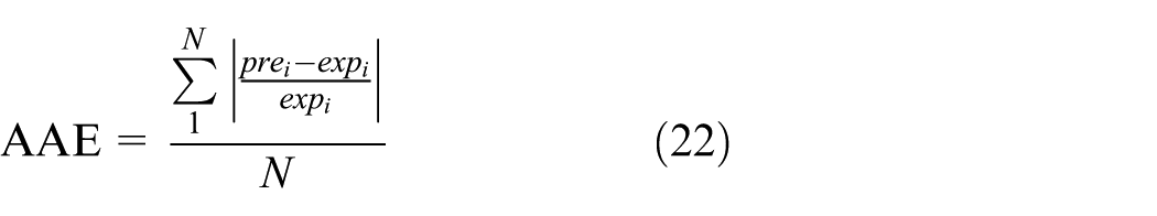

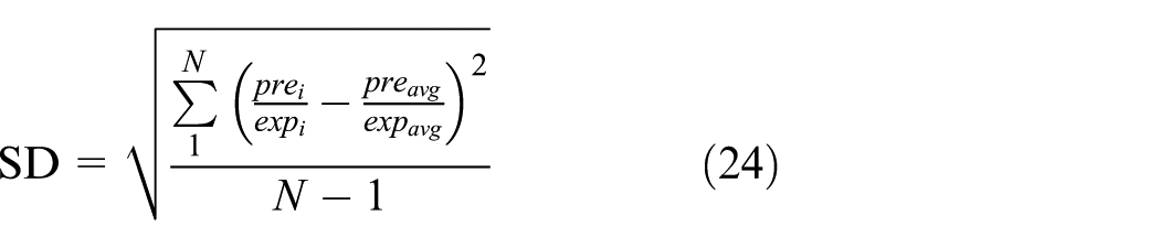
where pre is the model predictions, exp is the experimental results, the subscript avg indicates the average values, and N is the total number of specimens.
Table 2 shows the variables in the order of decreasing level of sensitivity such as the flexural stiffness parameter (IE/l), the projectile weight (M), the impact velocity (V), the compressive strength (
Sensitivity analysis of the proposed model.
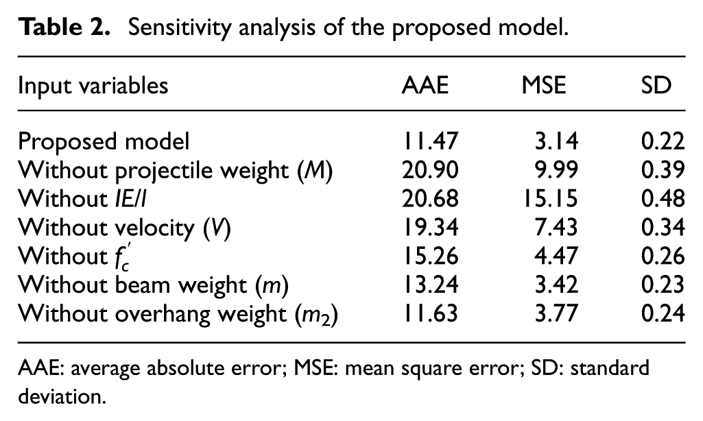
AAE: average absolute error; MSE: mean square error; SD: standard deviation.
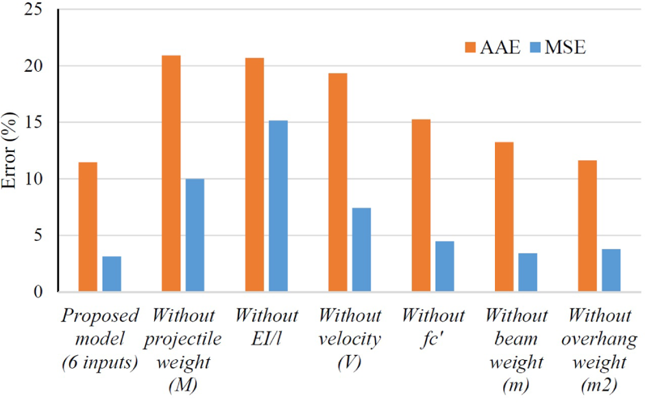
Results of sensitivity tests.
Simplified version of the proposed model
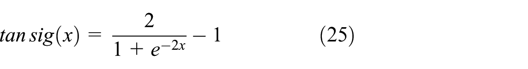
In the development of the proposed model, the “Tansig” transfer function is used as it provides better results than other transfer functions. Although the proposed model gives good predictions of the peak impact load on RC beams as proven above by comparing the prediction with the experimental data, the model is not straightforward to use. Users need to have fundamental knowledge of ANN and MATLAB to be able to use the proposed model. It is logical and possible that a functional-form equation could be explicitly derived from the trained networks by combining the weight matrices and the bias matrices. The final equations will become very complex because the proposed model contains complex transfer functions, which are “Tansig” as shown in equation (25). Therefore, in order to generate a simplified model to calculate impact force, the “Tansig” transfer function used in the previous section was replaced by the “Purelin” transfer function (equation (26)). Pham and Hadi (2014b) proposed a method that uses ANN to generate a user-friendly equation for predicting the compressive strength of FRP-confined concrete. This method is adopted in this study to build a simplified version of the proposed model. As a result, the simplified model could replace the ANN, which uses the “Purelin” transfer function, to yield the similar results. Once an ANN is trained and yields good results, a user-friendly equation could be derived following the procedure described below

The mathematical derivation of the method was presented in the study by Pham and Hadi (2014b); however, it is summarized herein to provide a brief background of the method. The architecture of the proposed model is modified to establish a simpler relationship between the input parameters and the impact force as shown in Figure 7. The following equations illustrate the notation in Figure 7
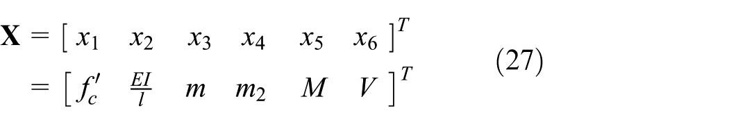
where
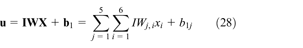


where

Architecture of the simplified model.
From equations (27) to (31) and Figure 7, the impact force could be calculated from the input parameters by the following equation

Based on equation (32), it is obvious that a user-friendly equation could be derived from a trained network. In order to simplify the proposed model, another expression could be derived as follows

where


Following the above procedure, the simplified model can be written as
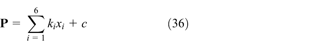
where ki are proportional factors and c is a constant. In this model, it is derived that c = −1119 and

The performance of the simplified model is presented in Figure 8. The AAE increases from 11.6% of the comprehensive version of the proposed model to 23.2% of the simplified model. Although the error of the simplified model significantly increases as compared to the comprehensive version of the proposed model, it provides a simple equation to predict the impact force, and the prediction accuracy is still better than the other approaches, for example, equation (16) based on conservation of energy.

Performance of the simplified model.
Conclusion
This study proposes a new ANN model to predict the maximum impact force on RC beams subjected to falling weight. The prediction from the proposed model fits the experimental results reasonably well with the AAE of about 11.6%. Since available models for estimating the maximum impact force in impact tests are rare and not straightforward to use, this proposed model may provide useful estimations of impact force for preparing the drop-weight testing and designing the impact resistance of RC beams subjected to falling objects. A simplified version of the proposed model is also presented, which can be straightforwardly applied to predict impact force on RC beams without performing ANN analysis. Although the simplified model yields a relatively larger error than the ANN model, its prediction accuracy is still better than other models commonly used for impact load predictions. In the future, as more data become available, the proposed ANN model can be retrained to achieve a higher degree of accuracy in impact load prediction.
Footnotes
Appendix 1
The input weight matrix
The input bias matrix
The layer weight matrix
The layer bias matrix
Declaration of Conflicting Interests
The author(s) declared no potential conflicts of interest with respect to the research, authorship, and/or publication of this article.
Funding
The author(s) received no financial support for the research, authorship, and/or publication of this article.