



Abstract
In this article, the mechanical behaviors of four kinds of specimens (i.e. aramid fiber–reinforced polymer sheets, steel-epoxy adhesive joints, concrete cubes, and aramid fiber–reinforced polymer-to-concrete joints) were evaluated, respectively, after the specimens were immersed in 35 g/L NaCl solution for up to 360 days. Test results show that (a) except for the tensile strength of the aramid fiber–reinforced polymer sheet related to an immersion time of 45 days being 5.0% higher than that of the control sheet, the change in the sheet’s tensile strength with the immersion time is not obvious, and the tensile strength of the sheet related to an immersion time of 360 days is almost the same as that of the control sheet; (b) the effect of the salt solution on the modulus of elasticity of the aramid fiber–reinforced polymer sheet is more significant than that on the tensile strength of the sheet, and the elastic modulus of the sheet related to an immersion time of 360 days is 11.1% lower than that of the control sheet; (c) the shear strength of the steel-epoxy adhesive joint experiences severe degradation after being immersed in the salt solution, but the compressive strength of the aged concrete cube is generally larger than that of the control cube; and (d) the maximum local shear stress in the aramid fiber–reinforced polymer-to-concrete joint generally shows a fluctuating increase with the increase in the immersion time, meanwhile the fracture energy of the joint generally increases with the increase in the immersion time, but the failure pattern of the joint with shorter immersion time is different from that with longer immersion time.
Keywords
Introduction
Fiber-reinforced polymer (FRP) has been considered to be an effective material for rehabilitating and strengthening concrete structures for decades, due to its excellent mechanical properties. The most widely used FRPs include glass fiber–reinforced polymer (GFRP), carbon fiber–reinforced polymer (CFRP), aramid fiber–reinforced polymer (AFRP), and hybrid fiber–reinforced polymer which is made of different kinds of fibers (e.g. carbon–glass hybrid fiber–reinforced polymer). Comparing among the three kinds of fibers (i.e. glass fiber, carbon fiber, and aramid fiber), the glass fiber is the cheapest, but its mechanical properties (e.g. strength and elastic modulus) are relatively weak, and the alkaline resistance of the glass fiber is comparatively inadequate; the carbon fiber is the most expensive, but it exhibits the highest strength and modulus of elasticity, and it also displays outstanding resistance to thermal, chemical, and environmental effects; and the aramid fiber has moderate cost, and its mechanical properties are also intermediate between the glass and carbon fibers. In China, the AFRP is chosen to be used to strengthen the metro tunnel structures, due to its good electrical insulation property relative to the CFRP and good mechanical properties relative to the GFRP. Since the tunnel structures are often exposed to the groundwater which contains a variety of chemical substances (e.g. chloride ion and sulfate ion), more attention should be paid to the durability of the AFRP-strengthened concrete structures in that environment. According to the Shanghai Geological Environmental Bulletin in 2014 (http://www.shgtj.gov.cn/dzkc/dzhjbg/), chloride ion is one of the two kinds of ions with much higher concentrations in the groundwater (e.g. the concentration of chloride ion ranges from 96.9 to 3236.6 mg/L in different aquifers). Among the literature regarding the durability of FRP-strengthened concrete members, the majority of that is concerned with GFRP or CFRP, and only a little is about AFRP. It has been experimentally demonstrated that the GFRP/CFRP-strengthened concrete members are affected by multiple environmental conditions (e.g. chloride salt, sulfate salt, alkaline condition, freeze-thaw cycling, wet/dry cycling, and ultraviolet radiation) more or less, but the influence of these environments on the AFRP-strengthened concrete members has not been studied extensively. Considering that this article is focused on the effects of salt solution on the mechanical behaviors of the AFRP sheets and AFRP-to-concrete joints, the following literature review is concentrated on the research pertaining to the salt condition.
Cromwell et al. (2011) investigated the mechanical behaviors of CFRP/GFRP immersed in the substitute ocean water at 22°C, prepared according to ASTM D1141 (2008: 3), for the durations of 1000, 3000, and 10,000 h. Cromwell et al. (2011) found that the CFRP plate performed better than the CFRP/GFRP fabrics. The tensile strength of the CFRP plate increased gradually with the increase in the immersing time, and the increase associated with the 10,000-h immersion was about 13%. However, the tensile strengths of the hand lay-up CFRP fabrics and GFRP fabrics increased after 1000-h immersion and then decreased at different levels with the increase in the immersing time, and slight loss of the tensile strengths was observed at the end of the 10,000-h immersion.
Sen et al. (1999) evaluated the durability of the bond between CFRP and concrete in marine environment through direct tension and direct torsion pull-off tests. In that study, the CFRP was bonded to 24 concrete slabs using five types of epoxy systems, and two salt conditions (i.e. combined wet/dry cycles and hot/cold cycles in 5% salt water, and wet/dry cycles in 15% salt water) were considered. Sen et al. (1999) observed that the bond strength loss ranged from 0% to about 50% after conditioning, and the bond strength’s degradation was scattered considerably for different types of epoxy systems. Generally, after the specimens were conditioned in the salt water, except those with Epoxy IV, the extent of debonding rose as compared with that of the control ones. Sen et al. (1999) concluded that the moisture absorption, not the mismatch in the thermal expansion coefficients between the CFRP, epoxy, and concrete, was more critical for the long-term performance.
The effect of thermal chloride solution on the behaviors of CFRP-concrete interface has been studied by Choi et al. (2012). Small beams with artificial saw-cut were strengthened by different CFRP systems and then were placed in chloride solution at 50°C for 12 months. After that the flexural strengths of the small beams were measured through three-point bending tests, and the results show that the flexural strength degradations were, respectively, 15.7%, 39.9%, and 71.3% for Systems A, B, and C, as compared with the failure load of the control specimen exposed to ambient environment for 12 months. Here, System A was composed of the epoxy saturant (tensile strength =55 MPa, modulus = 1724 MPa, Tg = 53°C), the unidirectional carbon-fiber weave (tensile strength =3800 MPa, modulus = 2.34 × 10⁵ MPa), and the top coating layer; System B consisted of the epoxy primer (tensile strength = 17.2 MPa, modulus = 715MPa, Tg = 77°C), the epoxy putty (tensile strength =15.2 MPa, modulus = 1790 MPa, Tg = 75°C), the epoxy saturant (tensile strength = 55.2 MPa, modulus = 3035 MPa, Tg = 71°C), the unidirectional carbon-fiber weave (tensile strength =3800 MPa, modulus = 2.28 × 10⁵ MPa), and the top coating layer; and System C was composed of the epoxy putty (tensile strength = 24.8 MPa, modulus = 4482 MPa, Tg = 62°C) and the unidirectional pultruded carbon-reinforced polymer laminate (tensile strength = 2800 MPa, modulus = 1.65 ×10⁵ MPa). All of the exposed systems displayed adhesive failure, except the samples of System C, which showed interlaminar failure.
Toutanji and Gomez (1997) investigated the flexural loading capacities of small-scale concrete beams strengthened with CFRP or GFRP sheets. These beams were subjected to 300 wet/dry cycles (in each cycle, the beams were immersed in 35 g/L salt solution for 4 h and then were dried in hot air at 35°C for 2 h). Toutanji and Gomez (1997) found that the wet/dry cycling leaded the bond between the concrete and FRP being weakened, resulting in the decrease in the loading capacities of the FRP-strengthened beams. The beams bonded using Epoxy I (i.e. modified amine/epoxy resin blend) experienced the highest reduction in strength between 19% and 33%, the beams bonded using Epoxy II (i.e. polyoxypropylenediamine hardener/epoxy resin) experienced a strength reduction between 10% and 24%, and those bonded using Epoxy III (i.e. amine saturant/solvent-free epoxy) experienced a strength reduction between 3% and 8%.
Chajes et al. (1995) also fabricated some FRP-strengthened small-scale concrete beams and evaluated the effect of wet/dry cycling condition on their overall behaviors. In that study, the strengthening materials included graphite fabrics, E-glass fabrics, and aramid fabrics. In each wet/dry cycle, the beams were all immersed in the calcium chloride solution consisting of 4 g anhydrous calcium chloride per 100 mL of water for 16 h and then were dried at room temperature for 8 h. After 0, 50, and 100 cycles, the strengths of the beams were measured through four-point bending tests, and Chajes et al. (1995) concluded that the chloride environment induced different levels of degradation to the beams’ strengths, and the beams bonded with the graphite fabrics were more durable than those bonded with the E-glass fabrics and aramid fabrics. All of the concrete beams bonded with the E-glass fabrics failed as a result of the tensile failure (tearing) of the fabric. Fabric tearing initiated failure and failure due to shearing of the concrete were observed, respectively, for the concrete beams bonded with the graphite fabrics and concrete beams bonded with the aramid fabrics in the control batch. However, all of the exposed aramid-reinforced beams and graphite-reinforced beams failed due to debonding of the fabric.
Silva and Biscaia (2008, 2013) investigated the effects of salt fog cycling and total immersion in salt solution on the behaviors of FRP-concrete joints by conducting four-point bending tests on special GFRP- and CFRP-strengthened concrete beams, which were formed by two independent prismatic concrete blocks connected through a stainless steel hinge device. The concentration of the salt water was 50 g of sodium chloride per liter of water, and each salt fog cycle consisted of 8 h of spray followed by 16 h of drying at 35°C. After 10,000 h, the strengths of the GFRP-strengthened beams were almost unaffected by the salt fog cycling, but the loading capacities of the strengthened beams immersed in the salt water increased by nearly 20%. On the other hand, with the increase in the aging time, the ultimate capacities of the CFRP-retrofitted beams subjected to salt fog cycling did not exhibit any regularity. In terms of the failure modes, salt fog cycles and immersion in salt water were associated with failure at the interface of concrete and adhesive, differing from failure in the concrete near-surface substrate of the reference beams, regardless of types of strengthening materials.
EI-Dieb et al. (2012) conducted research on the long-term (6 and 18 months) performance of reinforced concrete beams and slabs externally strengthened by CFRP exposed to sea water or sabkha soil condition. For the sea water exposure, the specimens were exposed to cycles of immersion in the sea water for 2 weeks followed by 2 weeks of natural drying. The concentration of chloride ions in the sabkha soil (157,200 mg/L, i.e., 4.43 mol/L) was almost 10 times higher than that in the sea water. Test results show that the sea water hardly brought adverse influence on the loading capacities of the CFRP sheets or strips strengthened members, and the ultimate loads of the members retrofitted with CFRP sheets embedded in the sabkha soil did not exhibit significant degradation, but the loading capacities of the beams and slabs strengthened with CFRP strips decreased by 25% and 10.7%, respectively, after 18-month embedding in the sabkha soil. The beams and slabs strengthened with CFRP strips failed only due to the peeling off of the strips, the beams strengthened with CFRP sheets subjected to wet/dry cycles in the sea water failed due to the peeling off of the sheets, but the other beams and slabs strengthened with CFRP sheets failed due to the tensile fracture of the sheets.
It can be seen from the above-mentioned literature that the effects of chloride condition on mechanical behaviors of the GFRP- or CFRP-strengthened concrete specimens have been studied by some researchers, but very limited information about the influences of that condition on mechanical properties of the AFRP-strengthened specimens is available now. Due to the increasing use of AFRP in strengthening concrete structures (e.g. AFRP-strengthened tunnel linings), it is necessary to conduct more research on the durability of the AFRP-strengthened concrete members. In this article, the effects of salt solution on the mechanical performance of AFRP sheets and AFRP-to-concrete joints have been experimentally investigated. Meanwhile, tests are also carried out to examine how that condition affects the mechanical behaviors of steel-epoxy adhesive joints and concrete cubes.
Experimental program
Specimen details
Four kinds of specimens (i.e. AFRP sheets, steel-epoxy adhesive joints, concrete cubes, and AFRP-to-concrete joints) were tested in this study.
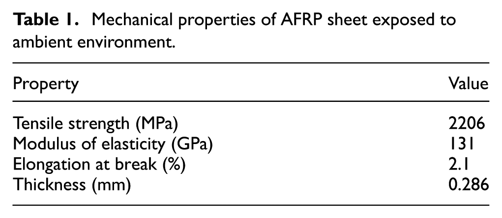
A total of 30 AFRP sheet specimens were prepared using the aramid fiber fabrics and epoxy adhesive through hand lay-up method. Both the fabrics and the adhesive were provided by Shiwei Construction Material Co., Ltd. The mean values of the mechanical properties of the AFRP sheet exposed to ambient environment provided by the producer are listed in Table 1. The schematic diagram and a photo of the AFRP sheet specimens, whose geometrical dimensions were determined according to ASTM D3039/D3039M-08 (2008: 13), are shown in Figure 1. To make the successful introduction of force into the specimen and to prevent premature failure of the specimen as a result of significant discontinuity, short CFRP strips and aluminum plates were bonded to both ends of the AFRP sheet using the epoxy adhesive also supplied by Shiwei Construction Material Co., Ltd. All the specimens were cured in air for 1 week, after that 25 of them were immersed in the salt solution for different immersion times at room temperature, and the other five were maintained under ambient conditions to serve as control specimens.
Mechanical properties of AFRP sheet exposed to ambient environment.
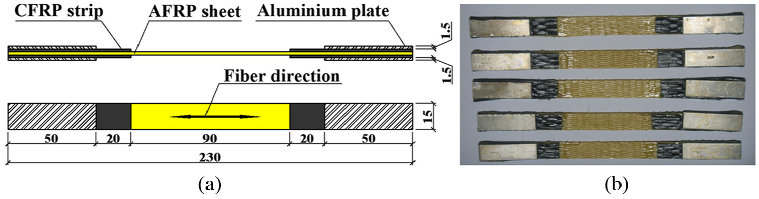
AFRP sheet specimens: (a) schematic diagram of specimen (unit: mm) and (b) photo of specimens.
A total of 30 steel-epoxy adhesive joint specimens were prepared. The epoxy adhesive was also provided by Shiwei Construction Material Co., Ltd, and was identical with the matrix of the aforementioned AFRP sheets. The mechanical properties of the epoxy adhesive exposed to ambient environment provided by the producer are as follows: tensile strength = 47.2 MPa, tensile modulus = 2.73 GPa, and ultimate strain =2.2%. The glass transition temperature, Tg, of the epoxy adhesive cured in air for 7 days was measured by the authors using a differential scanning calorimeter (NETZSCH DSC 204 F1 Phoenix) at a heating rate of 10°C/min. Three samples of the epoxy adhesive were prepared, and the glass transition temperature of each sample was measured. The average value of the measured glass transition temperatures of the three samples is 121°C with a coefficient of variation of 1.5%. The schematic diagram and a photo of the steel-epoxy adhesive joint specimens, whose geometrical dimensions were determined according to GB/T 7124-2008 (2008: 3), are shown in Figure 2(a) and (b), respectively. In each specimen, the dimensions of the overlapping area were similar to those prescribed in ASTM D3165-07 (2007: 4), and the thickness of the adhesive layer was maintained to be 0.2 mm by putting two iron wires with a diameter of 0.2 mm between the two stainless steel plates, as shown in Figure 2(c). According to GB/T 7124-2008 (2008: 3), the two iron wires were set to be in parallel with the loading direction to reduce their impact on the test results. All the specimens were cured in air for 1 week, after that 25 of them were immersed in the salt solution for different immersion times at room temperature, and the other five were exposed to ambient environment to serve as reference specimens.
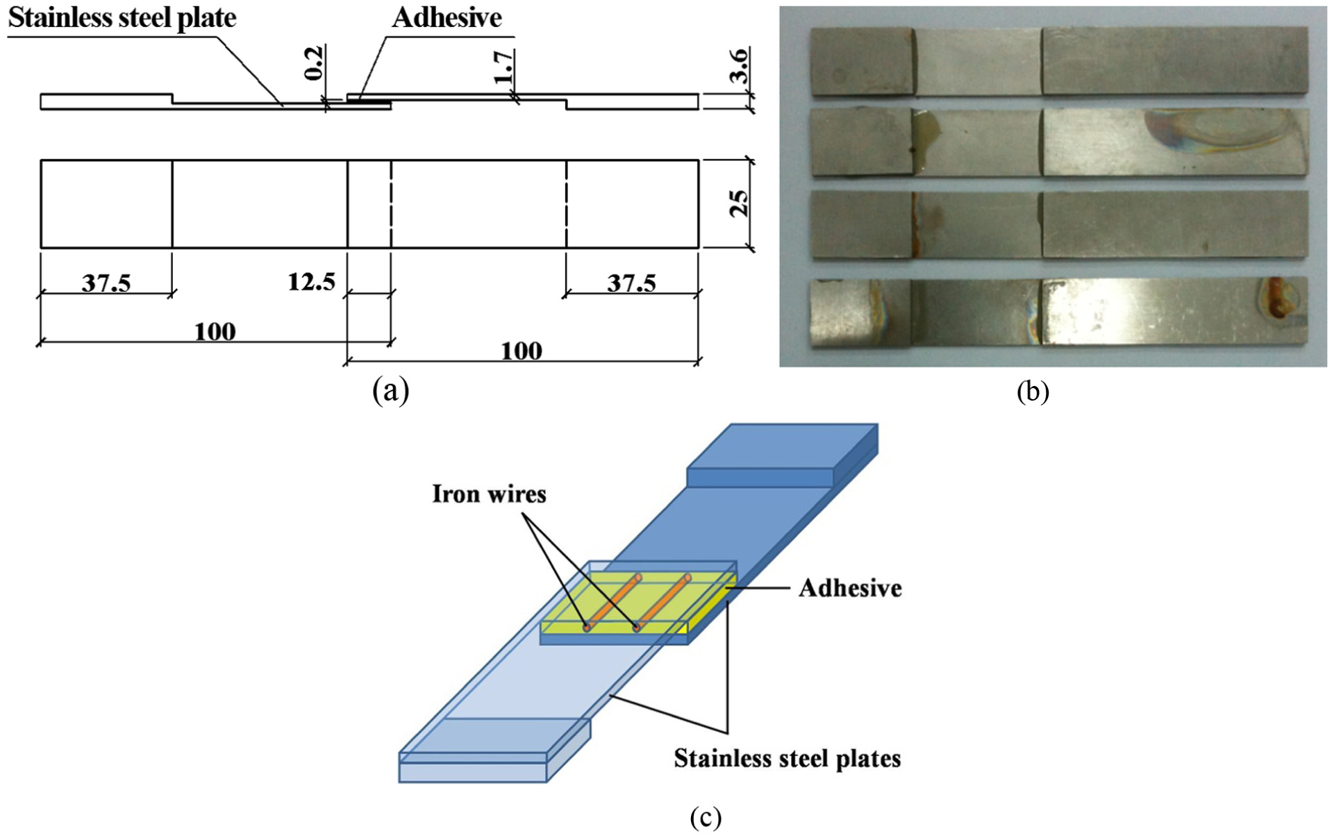
Steel-epoxy adhesive joint specimens: (a) schematic diagram of specimen (unit: mm), (b) photo of specimens, and (c) iron wires embedded in specimen.
A total of 30 concrete cube specimens (100 mm × 100 mm × 100 mm) were prepared from one batch of ready-mix concrete. The concrete was mainly made of ordinary Portland cement (P II 42.5 R specified in GB 175-2007 (2007: 6)), granite gravel with the size of 5–25 mm (coarse aggregate), and river sand with a fineness modulus of 2.6 (fine aggregate). The concrete mix proportion in terms of weight was 1.0 (cement):0.36 (water):1.54 (sand):2.46 (gravel). Five 150-mm cubes were cast along with the 100-mm cubes, and from which the 150-mm cubic compressive strength of the concrete was determined. The average value of the measured 28-day cubic compressive strengths of the concrete was 57.7 MPa with a coefficient of variation of 1.4%. All the 100-mm cubes were placed in air for 90 days, after that 25 of them were immersed in the salt solution for different immersion times at room temperature, and the other five as control specimens were only exposed to ambient environment.
A total of 30 AFRP-to-concrete joint specimens were prepared. Each specimen consisted of a concrete block with dimensions of 150 mm × 100 mm×75 mm and one layer of the aramid fiber fabric with a width of 50 mm and a length of 600 mm. The concrete block was made from the same batch of ready-mix concrete as used for the above-mentioned 100-mm concrete cubes and was cured in air for 83 days. The concrete surface of the block was roughened using a mechanical grinder to remove the surface laitance and then the dust on the surface was blown off by means of compressed air. After that, referring to the experimental practice of Biscaia et al. (2012, 2013, 2014), in which the double shear test was conducted to avoid the possibly unsymmetrical condition induced by the simple shear test, the aramid fiber fabric was bonded to two opposing sides of the concrete block using the aforementioned epoxy adhesive through wet lay-up method, as shown in Figure 3. Based on the measured modulus of elasticity of the AFRP sheet exposed to ambient environment (see Table 3) and the measured 28-day cubic compressive strength of the concrete, the effective bond length (Le) between the concrete and the aramid fiber fabric was estimated using equation (1) proposed by Chen and Teng (2001) and equations (2a) to (2c) given by Seracino et al. (2007)



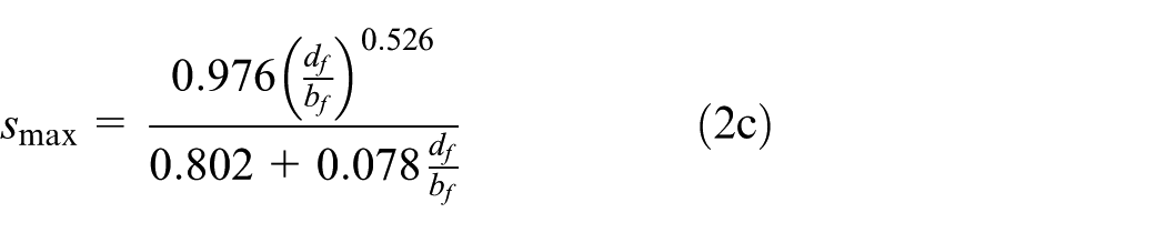
where Ef, tf, Af, and bf are, respectively, the modulus of elasticity, thickness, cross-sectional area, and width of the AFRP; fc is the cylindrical compressive strength of the concrete; df is the thickness of the failure plane perpendicular to the concrete surface (suggested value for externally bonded systems = 1 mm); and Lper is the length of the debonding failure plane which can be assumed as 2df + bf for externally bonded systems. The effective bond length estimated using equation (1) was about 70 mm and that estimated using equations (2a) to (2c) was about 40 mm. So, on two opposing sides of the concrete block, the bond lengths between the concrete and the aramid fiber fabric were chosen to be the same as 100 mm, which were longer than the aforementioned estimated effective bond lengths. All the specimens were kept in air for 1 week after they had been fabricated, then 25 of them were immersed in the salt solution for different immersion times at room temperature, and the other five as reference specimens were only exposed to ambient environment.
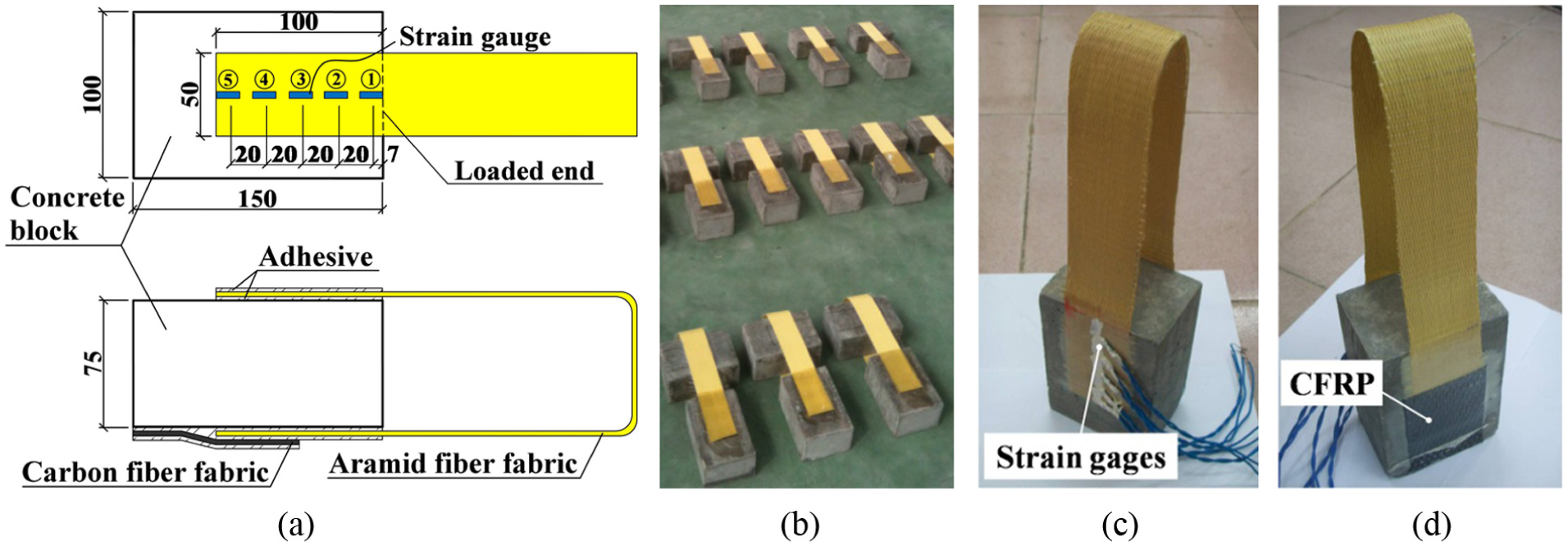
AFRP-to-concrete joint specimens: (a) schematic diagram of specimen (unit: mm), (b) photo of specimens, (c) the side with strain gauges (Side A), and (d) the side with CFRP (Side B).
Environmental conditionings
At present, there is no uniform standard for both the concentration of the salt solution and the corresponding aging time. Referring to the literature of other researchers (Abanilla et al., 2006; Al-Mahmoud et al., 2014; Karbhari and Ghosh, 2009; Robert and Benmokrane, 2013; Robert and Fam, 2012; Silva and Biscaia, 2008), the concentration of the salt solution was chosen to be 35 g NaCl per liter of water in this study, and the immersion times for the specimens included 45, 90, 180, 270, and 360 days at room temperature. Two plastic square barrels with a volume of 1500 L were employed as the containers in which the specimens were immersed. Due to the evaporation of water in the containers, the concentration of the sodium chloride solution would increase slightly, so a salinometer was used to check the solution’s concentration regularly, and tap water was added in the two containers to maintain the concentration within a range of 35 ± 1 g/L NaCl. The aging conditions are listed in Table 2 for all the specimens.
Aging conditions for specimens.
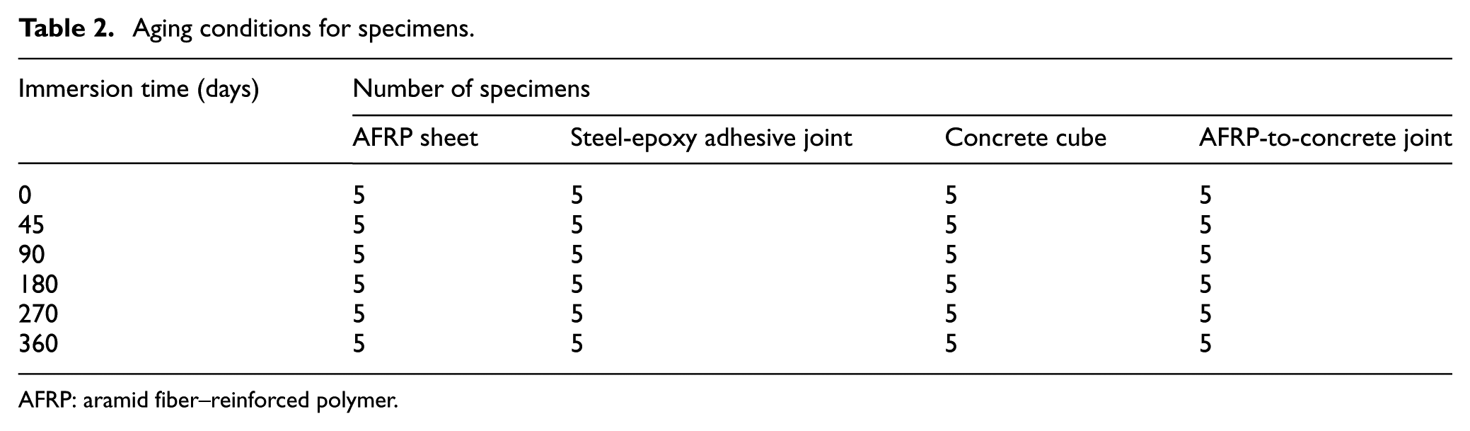
AFRP: aramid fiber–reinforced polymer.
Before the concrete cube specimens and the concrete blocks in the AFRP-to-concrete joint specimens were immersed in the salt solution, they had been cured in air for at least 90 days, so the hydration process of the concrete had almost finished before the immersion treatment.
After the four kinds of specimens were immersed in the salt solution for different times, the AFRP sheets and the steel-epoxy adhesive joints were naturally air dried for 1 week and the concrete cubes and the AFRP-to-concrete joints for 2 weeks. After that, the residual mechanical properties of these specimens were measured.
Test setups
The Instron 5567 testing machine with a loading capacity of 30 kN was employed to determine the tensile strengths of the AFRP sheets, the shear strengths of the steel-epoxy adhesive joints, and the load bearing capacities of the AFRP-to-concrete joints, as shown in Figure 4(a) to (c), respectively. To assure the tensile force was in parallel with the fiber direction of the AFRP-to-concrete joint, a special loading device as shown in Figure 5 was made and used in the test of the AFRP-to-concrete joint specimen.
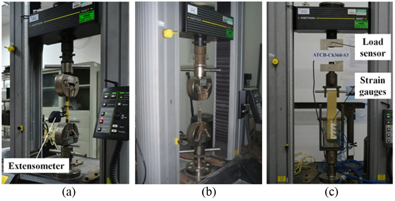
Test setups for three kinds of specimens: (a) AFRP sheet specimen, (b) steel-epoxy adhesive joint specimen, and (c) AFRP-to-concrete joint specimen.
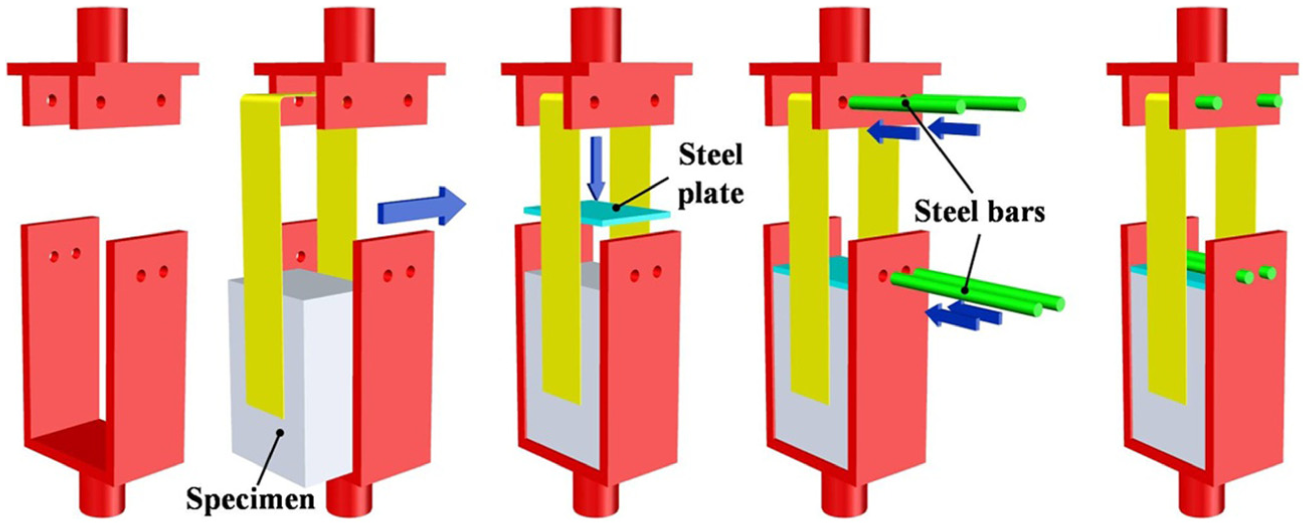
Schematic diagrams of special loading device for AFRP-to-concrete joint specimen.
The AFRP sheet specimen was stretched in the fiber direction at a rate of 2.0 mm/min according to ASTM D3039/D3039M-08 (2008: 13). As to the steel-epoxy adhesive joint, a loading rate of 9.0 MPa of the shear area per minute was adopted to meet the requirements specified in GB/T 7124-2008 (2008: 3) (8.3–9.8 MPa/min) and ASTM D3165-07 (2007: 4) (8.3–9.7 MPa/min). The AFRP-to-concrete joint was pulled monotonically under a displacement control up to failure, and a loading rate of 0.5 mm/min used in the tests of Toutanji and Ortiz (2001) was adopted in this study.
For each AFRP sheet specimen, an extensometer with a gauge length of 50 mm was clamped to the sheet (see Figure 4(a)) to measure the tensile strain of the specimen during the test. For each AFRP-to-concrete joint specimen after conditioning, five strain gauges were installed on the AFRP (i.e. the aramid fiber fabric saturated with the epoxy adhesive) which located on one side of the specimen (Side A), as shown in Figure 3(a) and (c), so the strain distribution of this AFRP along the loading direction could be measured during the test. Meanwhile, an extra CFRP with dimensions of 60 mm × 100 mm was bonded to the AFRP which is located on the opposite side of the specimen (Side B), as shown in Figure 3(d), to ensure that the failure only occurred on Side A. All the strain data were automatically recorded by a data logger (i.e. DongHua 3816) at a time interval of 5 s.
An electro-hydraulic loading machine with a capacity of 2000 kN was adopted to measure the compressive strengths of 100-mm concrete cubes. The loading process was displacement controlled at a strain rate of 15 × 10−6/s according to GB/T 50081-2002 (2002: 26).
Test results and discussion
AFRP sheet specimens
Failure patterns of some AFRP sheet specimens with different immersion times under tensile loadings are shown in Figure 6. Three typical failure modes can be roughly summarized from this figure as: (a) fracture occurring at about the middle of the AFRP sheet (e.g. the second specimen from the top in Figure 6(b)), (b) fracture occurring at the edge of the overlapping area of the AFRP sheet and the CFRP strips (e.g. the first and second specimens from the top in Figure 6(e)), and (c) splitting of the AFRP sheet (e.g. the second specimen from the top in Figure 6(a)). But some AFRP sheets failed in a combination of different typical failure modes.
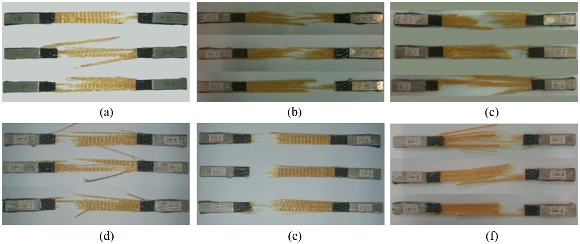
Failure patterns of AFRP sheet specimens with different immersion times under tensile loadings: (a) 0 days, (b) 45 days, (c) 90 days, (d) 180 days, (e) 270 days, and (f) 360 days.
The measured tensile stress–strain curve of a control specimen is shown in Figure 7. In this figure, Point A and Point B are related to 1000 and 3000 µε, respectively, and the secant stiffness between the two points is defined as the modulus of elasticity of the AFRP sheet according to ASTM D3039/D3039M-08 (2008: 13). It can be seen from Figure 7 that the axially loaded AFRP sheet did not exhibit any ductility and failed abruptly as expected.
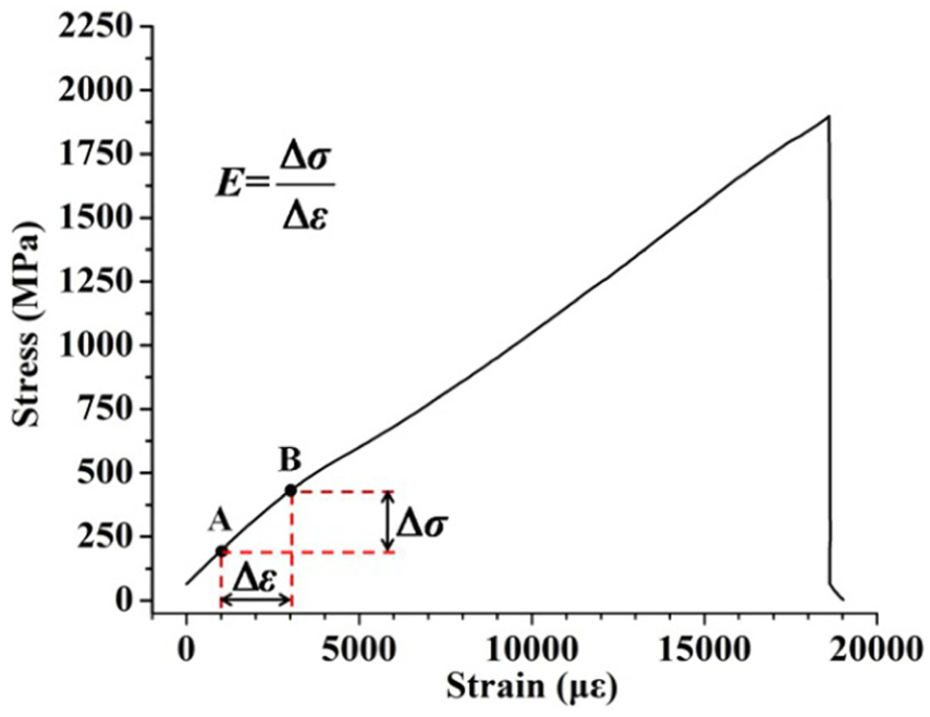
Measured stress–strain curve of a control specimen.
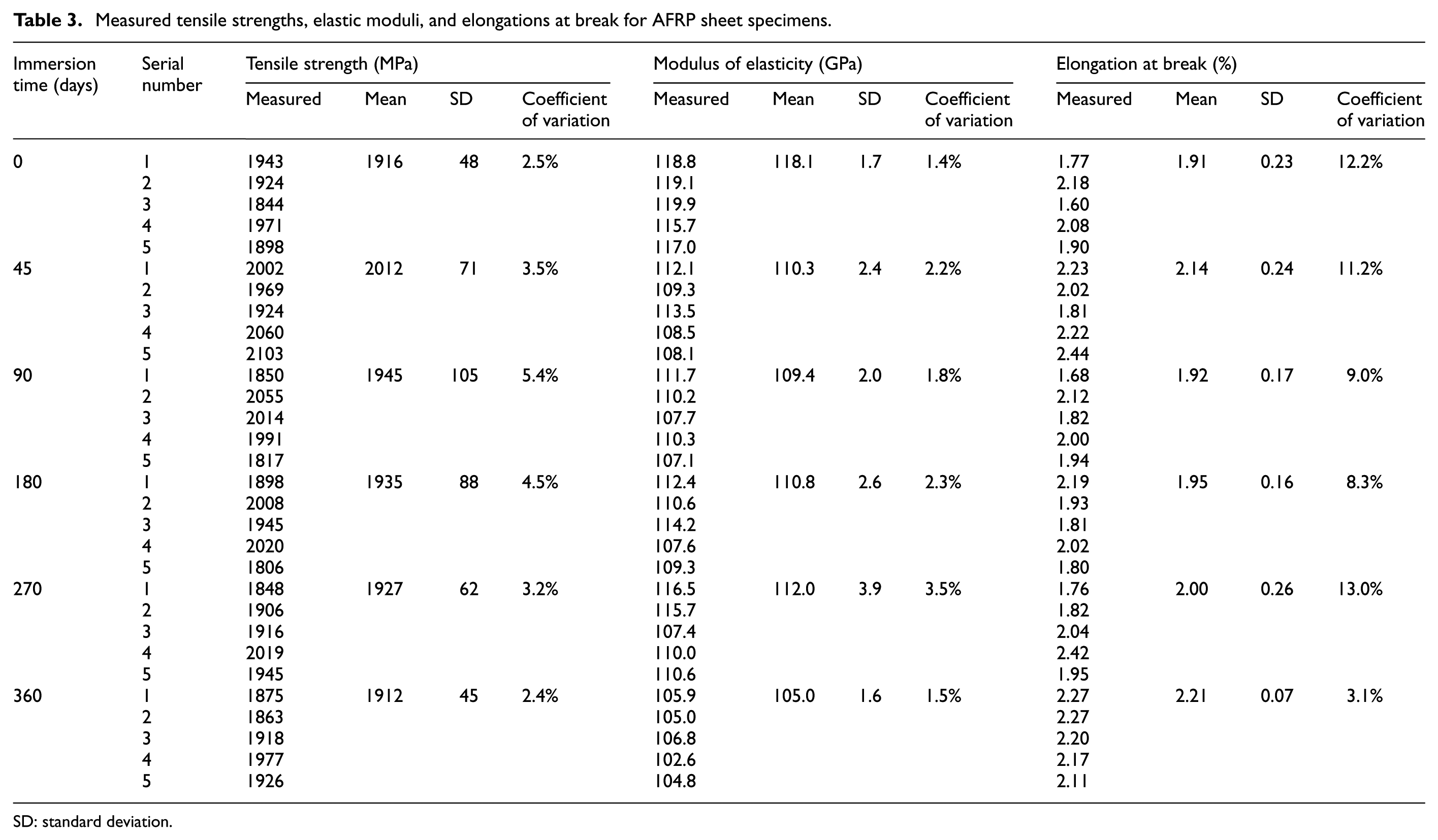
The measured tensile strengths, elastic moduli, and elongations at break are listed in Table 3 for all the AFRP sheet specimens. The tensile strengths and elastic moduli are compared with the test results provided by Abanilla et al. (2006) in a dimensionless manner, as shown in Figure 8. In the experimental studies conducted by Abanilla et al., the aging condition was the simulated salt water (5% NaCl solution) at 23°C, which is similar to that adopted in this article. It is found from Table 3 and Figure 8 that
Except for the average tensile strength of the AFRP sheets related to an immersion time of 45 days being 5.0% higher than that of the control specimens, the change in the average tensile strength of the AFRP sheets with the immersion time is not obvious, and the average tensile strength of the specimens related to an immersion time of 360 days is almost the same as that of the control specimens.
The average modulus of elasticity of the AFRP sheets related to an immersion time of 360 days is 11.1% lower than that of the control specimens, due to both the moisture-induced deterioration of the matrix (Alessi et al., 2011) and the salt crystals at the matrix–fiber interface. It has been pointed out in the literature (Alessi et al., 2011) that the moisture absorbed by the epoxy adhesive may induce some physical–chemical changes to the adhesive (e.g. plasticization and molecular modification), leading to a degradation of the adhesive. It can also be derived from the literature (Lin and Chen, 2005) that the elastic modulus of the epoxy adhesive is likely to be reduced due to the moisture in it, this obviously resulting in a deterioration of the mechanical properties of the matrix and in turn the AFRP sheet. In addition, the moisture plasticizes the matrix and then causes micro-cracks at the matrix–fiber interface. When the NaCl solution penetrates into the interface, salt crystals form and expand the micro-cracks, resulting in a decrease in the modulus of the composite (Belarbi and Bae, 2007). However, this decrease in the elastic modulus is not considered in ACI 440.2R-08 (2008: 76) for the design and construction of externally bonded FRP systems for strengthening concrete structures. According to the authors’ measured results in this study and the test results provided by other researchers (e.g. the test data shown in Figure 8(b) given by Abanilla et al.), it is suggested that a reduction in the elastic modulus of the composite subjected to long-term exposure to the salt condition should be taken into account in the design and construction of the FRP-strengthened concrete structures.
Except for the average elongation at rupture of the specimens related to an immersion time of 45 days, the average elongation at rupture of the AFRP sheets increases slightly with the increase in the immersion time on the whole, and the average elongation at rupture related to an immersion time of 360 days is 15.7% higher than that of the control specimens. This is generally in accordance with the above-mentioned finding (i.e. the effect of the salt solution on the elastic modulus of the AFRP sheet is more significant than that on the specimen’s tensile strength).
Referring to the unidirectional graphite/epoxy composite tested by Abanilla et al. (2006) after being immersed in 5.0% sodium chloride solution for periods of time up to 100 weeks, the tensile strength experiences an initial increase in the first 112 days followed by a decrease in the next 112 days and then keeps almost constant till the end of the conditioning. On the other hand, the modulus of elasticity increases in the first 28 days and generally decreases during the rest of the immersion time. Abanilla et al. (2006) attributed the initial increases in the tensile strength and modulus of elasticity to the post-cure of the matrix and attributed their following decreases to the moisture-induced deterioration of the resin and the fiber–matrix bond interface. Although the two curves in Figure 8(a) exhibit similar trends, the curve provided by Abanilla et al. (2006) seems to lag behind in timeline as compared with the curve obtained in this study, maybe due to the concentration of the salt solution adopted in this article being 30% less than that used in the literature (Abanilla et al., 2006). It is found from the literature (Kahraman and Al-Harthi, 2005; Tai and Szklarska-smialowska, 1993) that in the early stage of the immersing process, the higher the concentration of the NaCl solution, the slower the moisture diffuses into the epoxy resin. In this way, the moisture-induced degradation of the matrix of the graphite/epoxy composite in the literature (Abanilla et al., 2006) is postponed, as compared with the moisture-induced deterioration of the matrix of the AFRP sheet studied in this article.
Measured tensile strengths, elastic moduli, and elongations at break for AFRP sheet specimens.
SD: standard deviation.
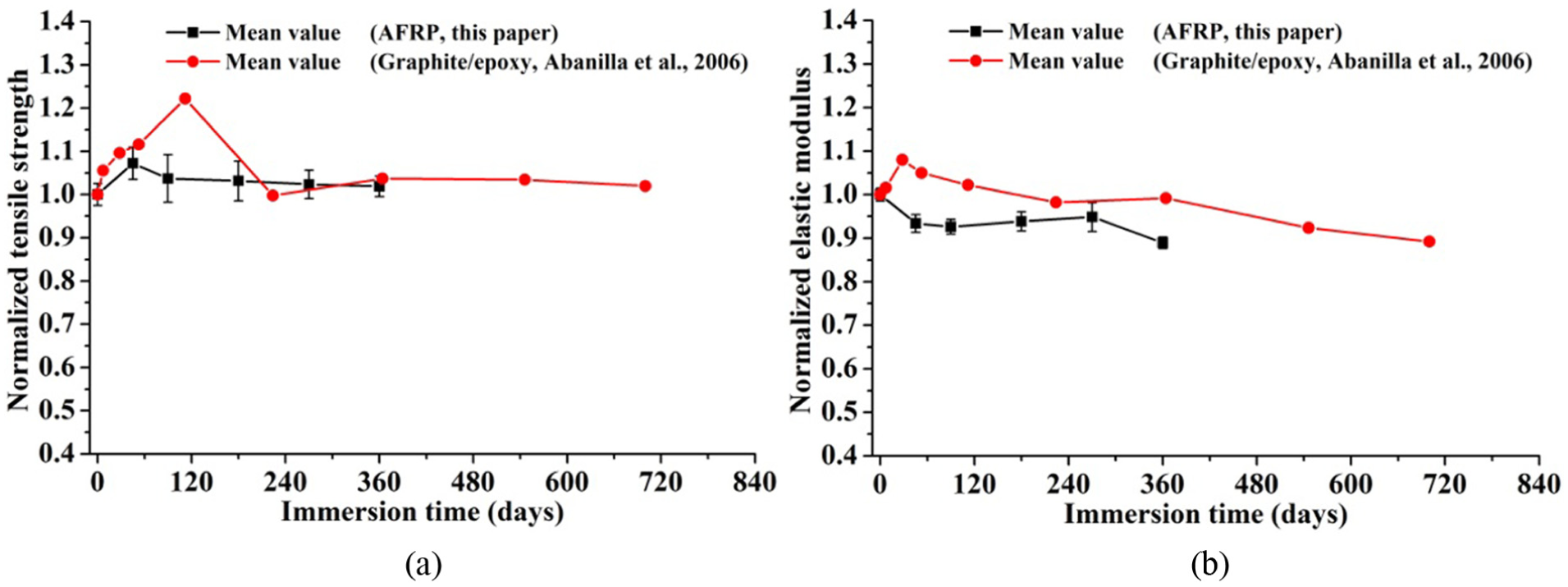
Comparisons between measured data of AFRP sheet specimens and test results provided by Abanilla et al. (2006): (a) normalized tensile strength and (b) normalized elastic modulus.
Steel-epoxy adhesive joint specimens
Failure patterns of some steel-epoxy adhesive joint specimens with different immersion times under shear loadings are shown in Figure 9. It can be seen from this figure that for each specimen, the adhesive only attaches to one of the two stainless steel plates after the shear test, regardless of the immersion time. This implies that the failure occurred at the interface between the adhesive and the steel plate during the shear test and not in the adhesive layer.
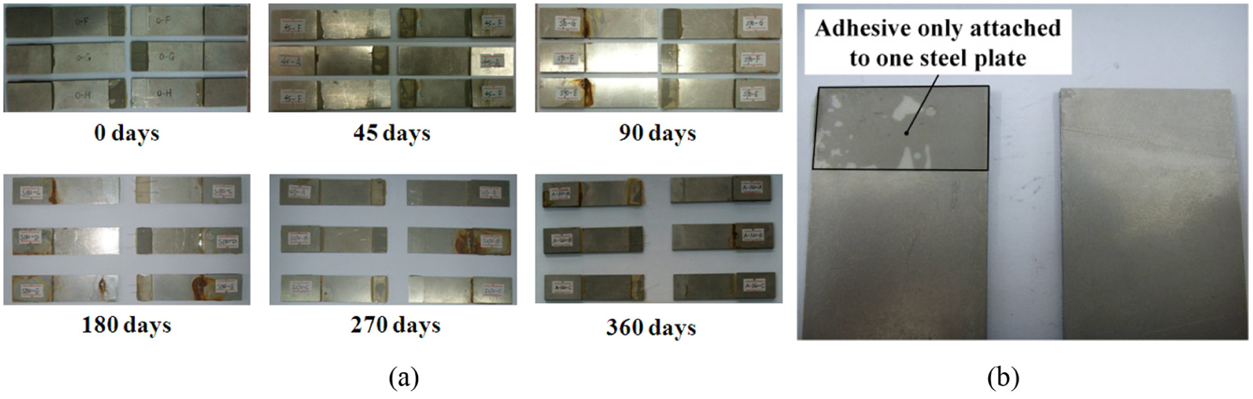
Failure patterns of steel-epoxy adhesive joint specimens with different immersion times under shear loadings: (a) overall pictures and (b) local photo.
The measured shear strengths are listed in Table 4 for all the steel-epoxy adhesive joint specimens. The shear strength is calculated through dividing the specimen’s failure load by the overlapping area of the two stainless steel plates (i.e. 25 mm × 12.5 mm in Figure 2(a)). The specimens’ normalized shear strengths with respect to the average shear strength of the control specimens are shown in Figure 10 and are compared with the test results provided by Hua et al. (2013). In the experimental studies conducted by Hua et al., the aging condition was the salt spray with a concentration of NaCl solution of 50 g/L at room temperature, which is somewhat similar to that adopted in this article. It should be noted that for simplicity, the area of the two iron wires placed between the two stainless steel plates is not deducted from 25 mm × 12.5 mm during the calculation of the shear strength, and the influence of the iron wires on the specimen’s shear strength is not taken into account at present. It is found from Table 4 and Figure 10 that
The average value of the normalized shear strengths of the specimens related to an immersion time of 360 days is 36% lower than that of the control specimens, indicating that the shear strength of the steel-epoxy adhesive joint obtained through the single-lap shear test experiences severe degradation after being immersed in 35 g/L NaCl solution; this is also attributed to the moisture absorbed by the adhesive (Alessi et al., 2011). Meanwhile, due to the plasticization of the aged epoxy, some micro-cracks may occur at the steel-epoxy interface. In this way, the NaCl solution can penetrate into the interface, then the chemical bond between the stainless steel plate and the adhesive is degraded by displacement of epoxy with water, and the salt crystals may form and expand the micro-cracks at the interface, both leading to the decrease in the joint’s shear strength.
Referring to the aluminum-epoxy adhesive joints tested by Hua et al. (2013) after being subjected to the salt spray condition for 0, 96, 168, 240, 360, 480, 720, 960, and 1200 h, the normalized shear strength of the joint increases within a spraying time of 240 h (i.e. 10 days) and then drops gradually with the increase in the spraying time. This initial increase may be caused by the moisture absorbed by the adhesive in the early aging time, which leads to the adhesive’s expansion and saturation, in turn to the release of the internal stress in the joint and consequently to the increase in the joint’s shear strength (Hua et al., 2013). But it should be noted that no initial increase is observed in Figure 10 for the steel-epoxy adhesive joints tested in this article, maybe due to the shortest immersion time being 45 days in our tests, which is much longer than the above-mentioned turning point (i.e. 10 days) of the test results provided by Hua et al. (2013). In this way, even if there is an initial increase in the normalized shear strength of the joint tested in this article within 44 days of immersion, we cannot get such information in this study. With respect to the decrease in the joint’s shear strength, it was explained by Hua et al. (2013) that the water molecules permeating into the joint aged in the salt spray fog induce a plasticization of the adhesive and then lead to the degradation of the adhesive.
Although the concentration of the NaCl solution in the literature (Hua et al., 2013) is about 43% higher than that in this article, the declining extent of the normalized shear strength of the aluminum-epoxy adhesive joint related to a spraying time of 45 days (i.e. 1080 h) is approximately equal to the degradation extent of the normalized shear strength of the steel-epoxy adhesive joint in this article related to an immersion time of 45 days.
Measured shear strengths of steel-epoxy adhesive joint specimens.
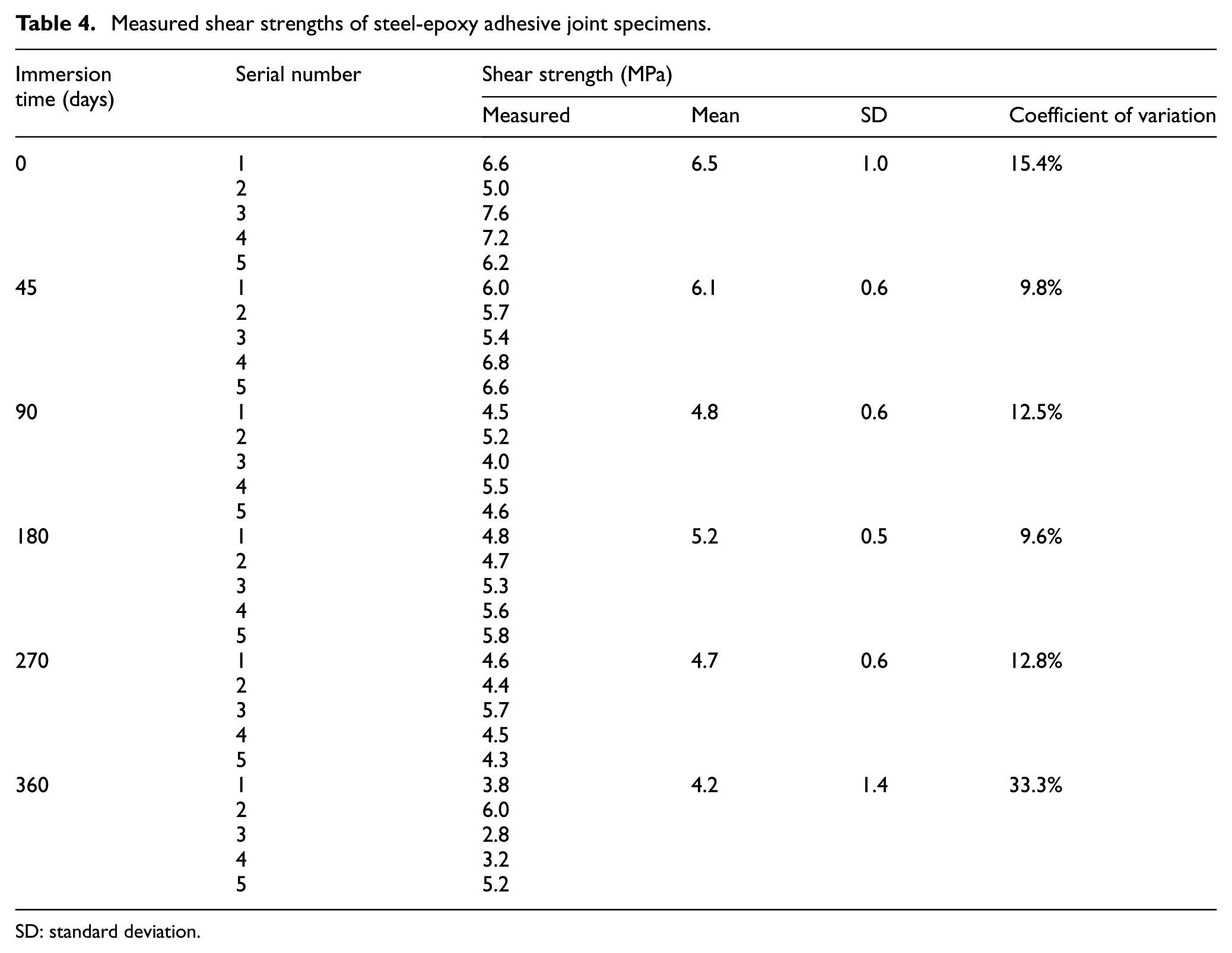
SD: standard deviation.
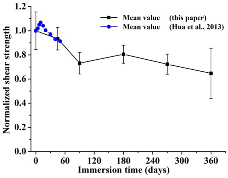
Comparisons between normalized shear strengths of steel-epoxy adhesive joint specimens and test results provided by Hua et al. (2013).
Concrete cube specimens
Variation of the measured compressive strength with the immersion time is shown in Figure 11 for 100-mm concrete cube specimens. In this figure, the average compressive strength of the control specimens cured in air for 90 days is obviously higher than the aforementioned 28-day cubic compressive strength of the concrete.
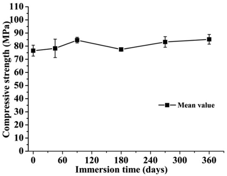
Variation of measured compressive strength with immersion time for 100-mm concrete cubes.
It can be seen from Figure 11 that the average compressive strength of the conditioned concrete cubes is generally larger than that of the control specimens (e.g. the average strength related to an immersion time of 360 days is 11% higher than that of the control specimens), maybe due to the moisture induced further hydration of the concrete. On the other hand, when the chloride ions in the salt solution penetrated into the concrete, Friedel’s salt could be formed in the pores of the concrete, resulting in a denser microstructure (Yuan et al., 2009) and in turn enhancement of the concrete strength.
AFRP-to-concrete joint specimens
Failure patterns of the AFRP-to-concrete joint specimens with different immersion times under pull loadings are shown in Figure 12. For each photo in this figure, the left part shows the surface of the concrete block from which the AFRP (i.e. the aramid fiber fabric saturated with the epoxy adhesive) was ripped, and the right part displays the back of the pulled-off AFRP. During the pull tests of the AFRP-to-concrete joint specimens with different immersion times, no rupture within the AFRP was observed. It can be seen from Figure 12 that the amount of cement mortar adhered to the back of the pulled-off AFRP with an immersion time of 0–90 days is generally more than that with an immersion time of 180–360 days, indicating that the bond between the concrete block and the AFRP generally deteriorated with the increase in the immersion time. This agrees with the finding mentioned above in section “Steel-epoxy adhesive joint specimens” (i.e. the shear strength of the steel-epoxy adhesive joint experiences severe degradation after being immersed in the salt solution). Chemical bonds and mechanical interlock between epoxy and concrete are the bonding mechanism between the concrete block and the AFRP. The chemical bonds, which mainly consist of hydrogen bonds, can be weakened in the presence of water, due to the hydrogen bonds being replaced by the water molecules. Meanwhile, the mechanical interlock is weakened by plasticization of the epoxy, which is induced by the moisture absorbed by the epoxy. Referring to the GFRP fabrics bonded concrete systems tested by Cromwell et al. (2011) after being immersed in the substitute ocean water for 1000, 3000, and 10,000 h, it is found that the failure of the systems without immersion treatment occurred from a concrete crack, while the failure of the immersed systems occurred in the adhesive layer and the FRP material. Obviously, this failure pattern transformation is somewhat similar to that observed in this study.
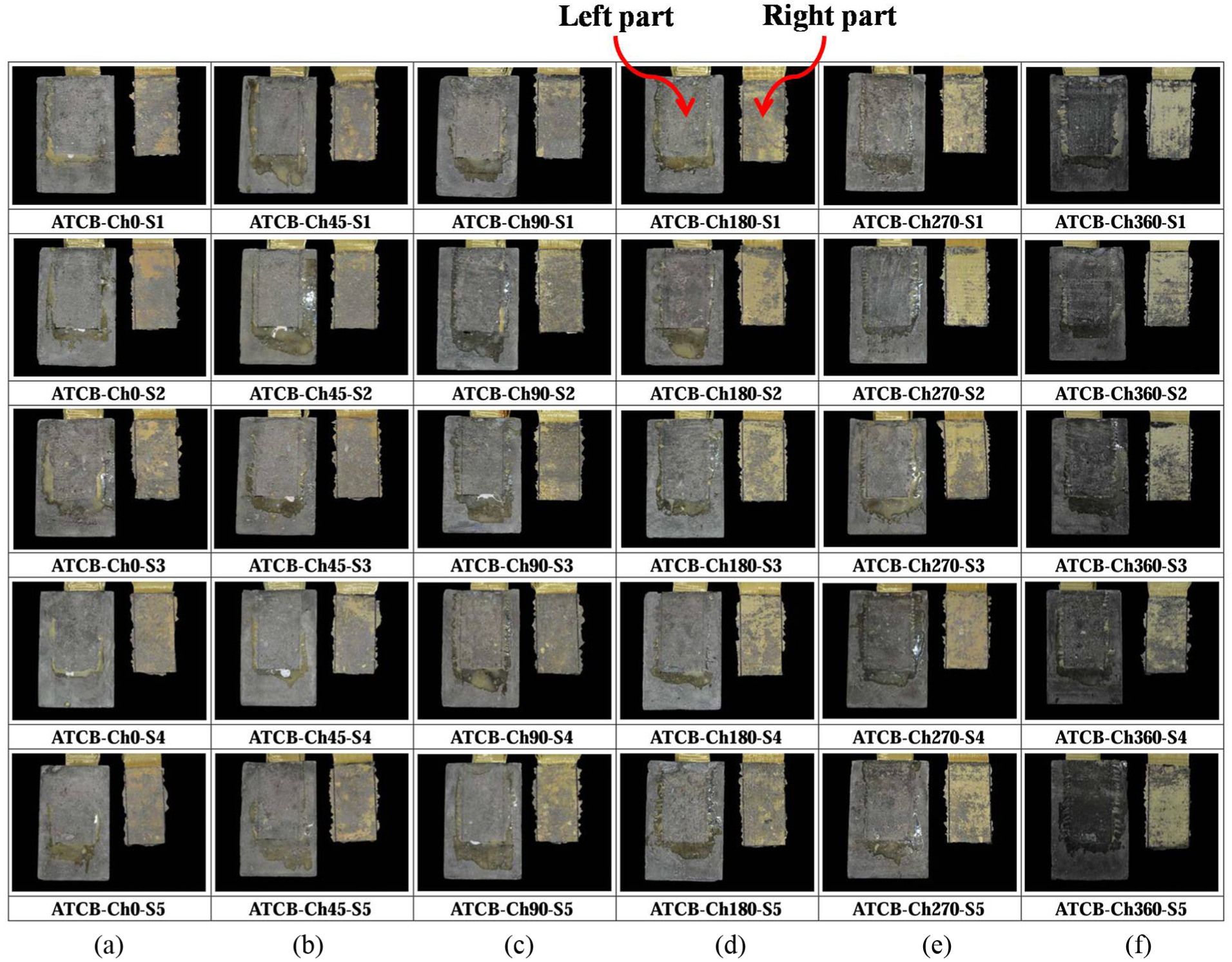
Failure patterns of AFRP-to-concrete joint specimens with different immersion times under pull loadings: (a) 0 days, (b) 45 days, (c) 90 days, (d) 180 days, (e) 270 days, and (f) 360 days.
For the typical AFRP-to-concrete joint specimens with different immersion times under pull loadings, the longitudinal strain distributions of the AFRP are shown in Figure 13(a) to (f). Variation of the maximum strain reached within the AFRP of the joint with immersion time is shown in Table 5. It can be seen from Figure 13 and Table 5 that
With the increase in the distance from the loaded end (see Figure 3(a)), the longitudinal strain of the AFRP generally reduces; when the applied load does not exceed 0.7Pu (Pu stands for the failure load) and the distance from the loaded end is larger than 47 mm, the longitudinal strain of the AFRP is very limited. Similar phenomenon can be observed in the literature (Kim et al., 2013) for CFRP-to-concrete joints.
When the applied load does not exceed a certain value (e.g. 0.7Pu in Figure 13(a) and 0.9Pu in Figure 13(b)), a more or less exponential trend appears in the strain distribution profile and extends over the region between Strain gauge ① and Strain gauge ③ (see Figure 3(a)). A further increase in loading leads to a change in the exponential-type strain distribution profile. The distance from the loaded end to the Strain gauge ③ is 47 mm, which is called the initial transfer length according to the definition in the literature (Bizindavyi and Neale, 1999) (i.e. the distance from the loaded end to the point where the exponential strain profiles reach zero strain), and can also be named as the effective bond length according to Chen and Teng’s study (Chen and Teng, 2001). It is obvious that the value of 47 mm is hardly affected by the immersion time, implying the influence of the immersion time on the initial transfer length being very limited.
With the increase in the applied load, the longitudinal strain of the AFRP generally increases; but when the applied load reaches the failure load Pu, the maximum strain of the AFRP is lower than 9000 µε, which is less than half of the measured elongation at rupture of the AFRP sheet (see Table 3), implying that the tensile capacity of the AFRP in the AFRP-to-concrete joint cannot be fully utilized.
With the increase in the immersion time, the mean value of the maximum strains reached within the AFRP fluctuates within a range of (7800 µε, 8700 µε, and does not show the trend of monotonic change.
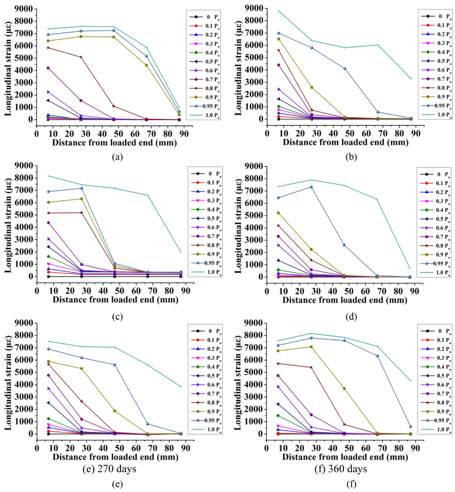
Strain distributions of AFRP in AFRP-to-concrete joint specimens with different immersion times under pull loadings: (a) 0 days, (b) 45 days, (c) 90 days, (d) 180 days, (e) 270 days, and (f) 360 days.
Maximum strain reached within AFRP.
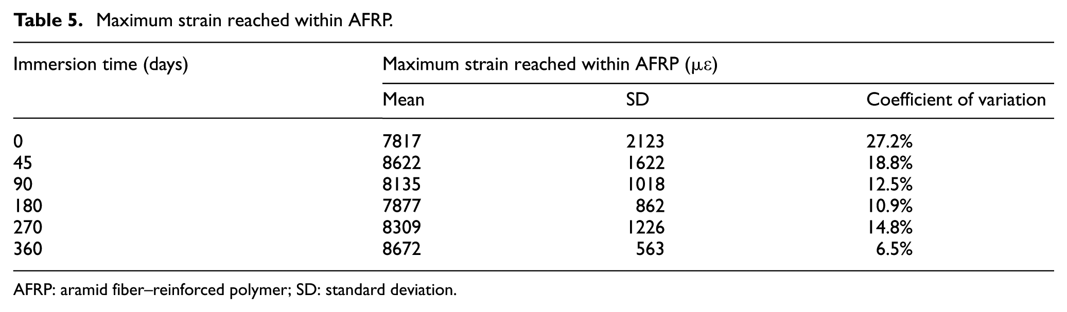
AFRP: aramid fiber–reinforced polymer; SD: standard deviation.
A schematic diagram of the internal forces in the AFRP is shown in Figure 14. In this figure, τi refers to the local shear stress in Segment i (i = 1, 2, 3, 4); Ef, tf, and bf are, respectively, the modulus of elasticity, the thickness, and the width of the AFRP; εi and εi + 1 are, respectively, the measured strains related to the ith and (i + 1)th strain gauges; and Δx = 20 mm (see Figure 3(a)) is the interval of neighboring strain gauges.
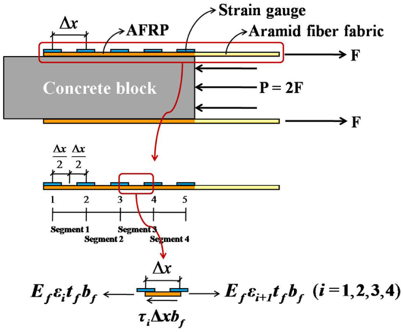
Schematic diagram of internal forces in AFRP.
Considering the equilibrium of the internal forces in the AFRP, equation (3) can be obtained to determine the local shear stress τi (i = 1, 2, 3, 4). In consideration of the accumulation of the relative deformations between the concrete block and the AFRP, equation (4) is established to determine the local bond slip at the middle of Segment i (named as si hereafter, i = 1, 2, 3, 4). Based on the measured longitudinal strains of the AFRP in the AFRP-to-concrete joint specimen, the local shear stress between the concrete block and the AFRP and the local bond slip between them can be, respectively, calculated using equations (3) and (4)

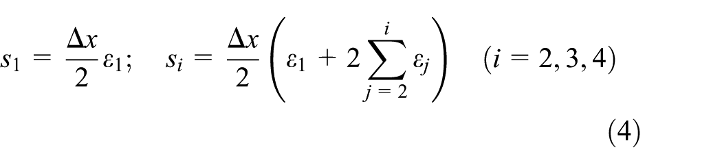
The calculated maximum local shear stresses and maximum local bond slips are shown in Figure 15 for the AFRP-to-concrete joint specimens after being immersed in the salt solution, in which the maximum local shear stress τmax = max(τ1(P), τ2(P), τ3(P), τ4(P)) (0 ≤ P ≤ Pu) and the maximum local bond slip smax = max(s1(P), s2(P), s3(P), s4(P)) (0 ≤ P ≤ Pu). Since no softening behavior was observed during the tests, the maximum local bond slip is related to the failure load of the specimen (i.e. Pu), and we have smax = s4(Pu) according to equation (4). It can be seen from Figure 15 that
The maximum local shear stress, τmax, generally shows a fluctuating increase with the increase in the immersion time. Except for the AFRP-to-concrete joint specimens immersed in the salt solution for 45 days, the average value of τmax for the joints immersed in the salt solution for a certain period of time is higher than the average value of τmax for the control specimens, this is, to some extent, similar to that observed in the study of Silva and Biscaia (2008). This phenomenon is partly due to the possible improvement of concrete tensile strength induced by wet curing of the concrete substrate. It should be noted that the relatively lower maximum local shear stress is related to the failure mostly occurred in the concrete substrate, as shown in Figure 12(a) to (c), and the relatively higher maximum local shear stress is corresponding to the adhesive-concrete interface failure, as shown in Figure 12(d) to (f).
The influence of the immersion time on the maximum local bond slip, smax, is limited, implying that the influence of immersion in the salt solution on the deformability of the AFRP-to-concrete joint is limited on the whole.
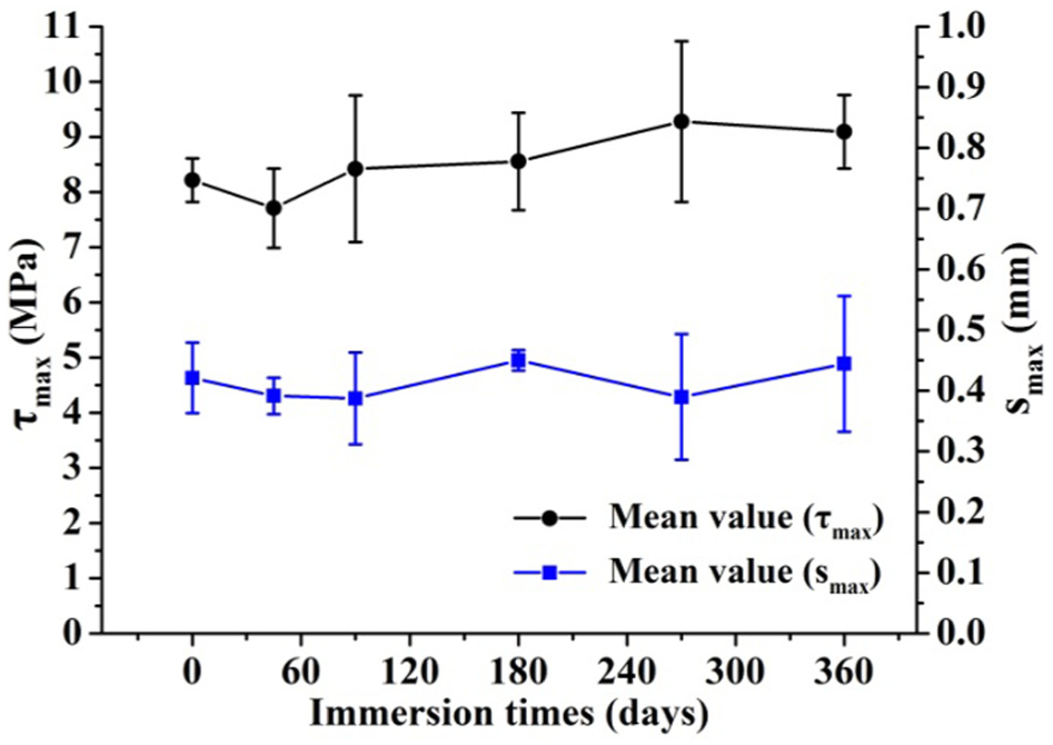
Variations of calculated maximum local shear stress and maximum local bond slip with immersion time.
The typical local shear stress–local bond slip curves of some AFRP-to-concrete joint specimens are shown in Figure 16, and the corresponding fracture energies are calculated and also listed in this figure. The fracture energy is the area under the local shear stress–local bond slip curve, which represents the energy per unit of bonded area required to fracture the interface. It can be seen from Figure 16 that (a) the shape of these curves is similar to that observed by Nakaba et al. (2001) and Silva et al. (2013); (b) the ascending branches of different curves are very close to each other, implying the initial stiffness of the joint being not affected by the aging in the salt water; and (c) the difference between the descending branches of different curves is significant, meanwhile the fracture energy of the joint generally increases with the increase in the immersion time.
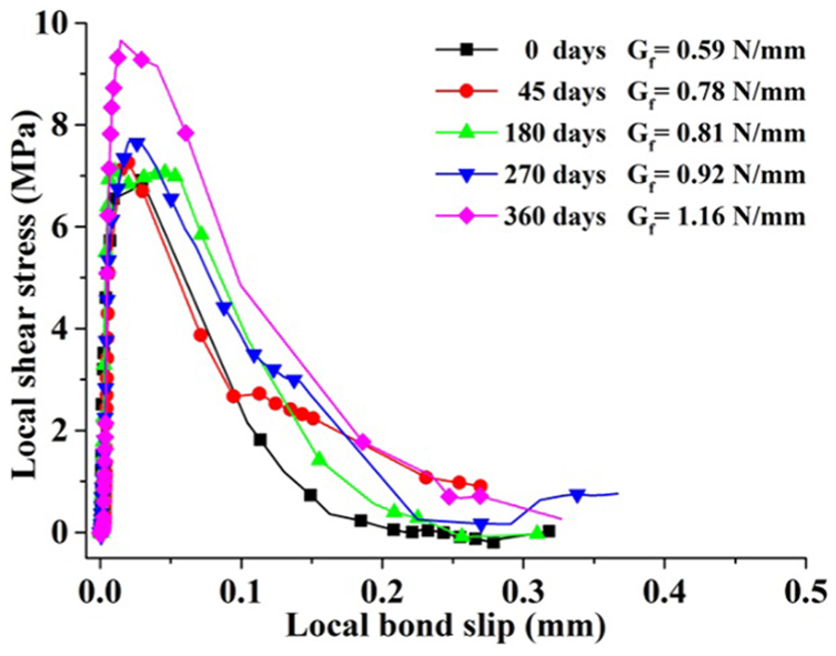
Local shear stress–local bond slip curves of AFRP-to-concrete joint specimens.
Conclusion
The effects of 35 g/L NaCl solution on the mechanical behaviors of AFRP sheets, steel-epoxy adhesive joints, concrete cubes, and AFRP-to-concrete joints have been experimentally examined within 360 days. Based on the test results, the following conclusions can be drawn:
Except for the tensile strength of the AFRP sheet related to an immersion time of 45 days being 5.0% higher than that of the control sheet, the change in the sheet’s tensile strength with the immersion time is not obvious; the modulus of elasticity of the sheet related to an immersion time of 360 days is 11.1% lower than that of the control sheet, implying the effect of the salt solution on the sheet’s elastic modulus being more significant than that on the sheet’s tensile strength. This reduction in the elastic modulus of the AFRP sheet is suggested to be considered in the design and construction of the AFRP-strengthened concrete structures subjected to long-term exposure to the salt condition.
The shear strength of the steel-epoxy adhesive joint related to an immersion time of 360 days is 36% lower than that of the control joint, indicating that the shear strength of the joint obtained through the single-lap shear test experiences severe degradation after being immersed in the salt solution.
For the AFRP-to-concrete joints after being immersed in the salt solution, the amount of cement mortar adhered to the back of the pulled-off AFRP with an immersion time of 0–90 days is generally more than that with an immersion time of 180–360 days, indicating that the bond between the concrete block and the AFRP generally deteriorates with the increase in the immersion time.
For both the AFRP-to-concrete joint exposed to ambient environment and the joint after being immersed in the salt solution, no rupture within the AFRP was observed during the pull tests of the joints, implying that the tensile capacity of the AFRP cannot be fully utilized when the joint fails.
For the AFRP-to-concrete joint after being immersed in the salt solution and then subjected to the pull loading, the maximum strain in the AFRP does not show the trend of monotonic change with the increase in the immersion time; meanwhile, the maximum local shear stress generally shows a fluctuating increase with the increase in the immersion time.
The fracture energy of the AFRP-to-concrete joint generally increases with the increase in the immersion time.
Footnotes
Declaration of Conflicting Interests
The author(s) declared no potential conflicts of interest with respect to the research, authorship, and/or publication of this article.
Funding
The author(s) disclosed receipt of the following financial support for the research, authorship, and/or publication of this article: The research reported was financially supported by the National Basic Research Program of China (973 Program: 2011CB013800), Water Science and Technology Innovation Project of Guangdong Province (2012-05), and the State Key Laboratory of Subtropical Building Science of China (2013KB29 and 2015ZB21). The financial supports are highly appreciated.