



Abstract
In this work, a recently patented seismic damper to be applied to structures composed by systems of panels is presented. In particular, the article is devoted to characterize the behaviour of the proposed connector by means of an experimental and numerical analysis and to provide some information about the cost of the elements needed to realize the damper, accounting for the manufacturing process. The experimental analysis has regarded five specimens tested under different loading conditions, and it has been used as a term of comparison with the classical systems of connection currently employed in these structures. Afterwards, in the article, a design criterion able to control the capacity and ductility of the device by simply varying the shape of the damper is presented and its accuracy is evaluated by performing finite element analyses. The results of the experimental and finite element analyses are very promising in terms of cyclic behaviour and energy dissipation capacity and reveal that the design of the element can be accurately controlled by means of the proposed approach. Furthermore, the cost estimate has revealed that the proposed damper is also cheaper than the classical solutions with a cost reduction of about 40%.
Introduction
Recent trends in the construction market are more and more oriented on systems based on the strong prefabrication and modularization of the structural and non-structural elements, with the aim to reduce the initial costs and to improve the quality of the final product. The advantages of prefabrication are evident and well known since many years such as the reduced cost, the increased quality, the improved safety, the reduced schedule, the reduced social and environmental impact and possibility to easily control the energy efficiency. In the last two decades, especially prior to the deep economic crisis that has strongly limited the initial impulse provided by some companies of the sector, many pre-fabricated systems for housing and the construction of industrial buildings have been proposed (Ceccotti et al., 2006; Hajjar et al., 2013; Iuorio et al., 2014). Among these, structures based on the dry assembly of panels made of wood, steel or precast concrete, in some cases also fully integrated with piping and electrical plants, have emerged as an alternative solution to the classical approaches, even in countries classically oriented on the most traditional construction systems, such as those of the Mediterranean area (Figure 1).
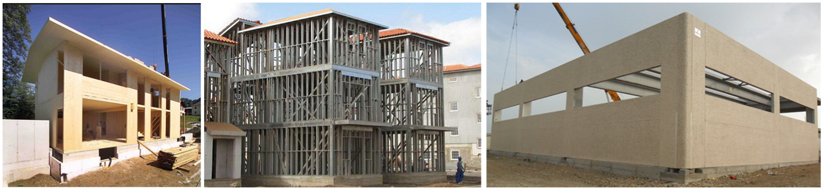
Different structural systems with wood, steel and concrete dry-assembled panels.
Examples of companies that have promoted structural systems for housing or for industrial buildings composed by the assembly of panels made with different materials can easily be found in many countries. For instance, in the wood market, recently, many European companies have proposed and advertised, even with the support of well-recognized research projects (e.g. SOFIE project), systems based on the application of cross-laminated timber (CLT) panels (Ceccotti et al., 2000, 2006, 2007). In the same way, also in the field of steel structures, even though they are not completely new, systems based on the dry assembly of pre-fabricated lightweight steel panels (light-gauge structures) have been recently promoted in many countries (e.g. Japan, United States, Canada, northern and southern Europe), with a high number of practical applications and research studies. Similarly to wood and steel, even though with a lower impact on the market, also in the field of concrete structures, systems based on the dry assembly of lightweight precast concrete panels have been recently proposed by many companies for housing especially in countries undergoing a fast growth of the second and third world (India, many African countries, etc.). Furthermore, on the European level, analogously to housing, also in the field of pre-fabricated industrial buildings, systems based on the combination of internal concrete frames with external claddings made with strong and rigid concrete walls are very common. All these systems, apparently very different, have in common the basic concept of assembling the building starting from pre-fabricated rigid panels (made of wood, concrete or steel) integrated with non-structural elements or, in the case of the industrial buildings, complementary to an internal structure which is used to resist the seismic actions.
The diffusion of the systems for housing in earthquake-prone regions, such as those of southern Europe, has recently raised the problem of their resistance to seismic actions. In fact, such typologies have been traditionally applied especially in non-seismic regions, such as those of northern-Europe, and, due to this reason, they usually employ connections (angle brackets, hold-downs, nails and screws) not specifically conceived for cyclic loading conditions. As an example, due to this need, recently, a great experimental effort has been devoted to the study of the behaviour of CLT panel buildings under seismic actions within national and international projects in Italy, Slovenia and Canada. Such studies have mainly dealt with the cyclic behaviour of the traditional connections, investigating their ability to dissipate the seismic input energy. In fact, in these structural typologies, the walls are very stiff and resistant and, due to this reason, the energy dissipation capacity is usually concentrated in the connecting elements, namely, the screws or the angles used to join the panels. These projects have outlined that panels’ structures, even though they are suitable for low-rise buildings, due to their low energy dissipation capacity, provide significant drawbacks when employed in high seismic regions. In fact, the behaviour of the typical connections employed in these systems (normally angles to absorb shear actions and hold-downs to absorb bending actions) is characterized by narrow hysteresis loops with pinching and strong degradation phenomena (Ceccotti et al., 2006; Dujic, 2001; Gavric et al., 2011). Due to this reason, with the typical connections’ layout, such structures can rely only on small values of the behaviour factor (q = 2 in EC8), leading to a significant oversizing of the panels and the foundations. In addition, such a low dissipation capacity represents a significant burden when these technologies have to be applied to multi-storey buildings and in fact, many national and international codes, their application is limited only to low-rise buildings.
Within this framework, in order to overcome the limitations provided by the adoption of the classical connections in Latour and Rizzano (2012, 2015a, 2015b), a new type of dissipative connection, called ‘AD-XLAM’, to be applied in substitution of the classical hold-downs was proposed and patented. The angle is characterized by a very high-energy dissipation capacity due to the particular shape of the flange plate. In fact, it is a plate carved with oxy-fuel or laser cutting in order to obtain regions with an hourglass shape where the width of the plate varies accordingly with the value of the bending moments developing on the plate under tension loads. Such a concept is mainly inspired to the classical added damping and stiffness (ADAS) or triangular-plate added damping and stiffness (T-ADAS) devices and represents the application of this idea to a steel angle to be used in walled structures in order to absorb the seismic input energy. The patent was released with the following main claim:
A connecting device for building structure, the building structure comprising at least two structural members; the connecting device comprising a first member for fixing the connecting device to one of the structural members and a second member for fixing the connecting device to the other structural member; the first member and the second member being joined to each other; and the connecting device being characterized in that the second member comprises lateral edges with respective recesses defining a deformation-absorbing region of the second member. (Latour et al., 2013)
In the next paragraphs, in order to clarify the concept at the base of the patented connector, the results of an experimental campaign carried out at the laboratory of materials and structures of the University of Salerno are briefly introduced. In addition, in order to fully show the potentialities of the patented device, an example of design of different geometries of four alternative solutions of the proposed connector, characterized by the same resistance of one of the hold-downs currently used to build housing with the cross-lam technology, but by a ductility five times higher, is presented. In particular, in order to provide the comparison, the following steps are developed:
Design of four AD-XLAMs with different geometries characterized by an ultimate resistance equal to the resistance of the reference hold-down (100 kN) and by a ductility five times higher;
Finite element (FE) modelling of the traditional hold-down with ABAQUS 6.11 and comparison with the experimental results;
FE modelling of the four different AD-XLAMs;
Comparison with the numerical results;
Comparison in terms of cost of the different devices.
Concept of the device and experimental behaviour
The patented device follows the same principle applied to metallic hysteretic dampers working in double curvature, such as ADAS devices (Whittaker et al., 1989). The main idea is to shift the dissipative zone of the hold-down from the stem of the angle to the flange plate. To this scope, the stem zone is over-strengthened by adopting a proper number of nails in order to concentrate yielding in the flange plate. In addition, the flange plate of the angle is weakened in order to obtain an hourglass shape very similar to that usually adopted in ADAS devices (Figure 2(a)). In fact, it is intuitive to understand that if the flange plate of the angle is cut providing a law of the width which varies accordingly with the diagram of the bending moment, it is ideally possible to get the contemporary plasticization of all plate sections obtaining a ductility demand distributed along the whole plate.
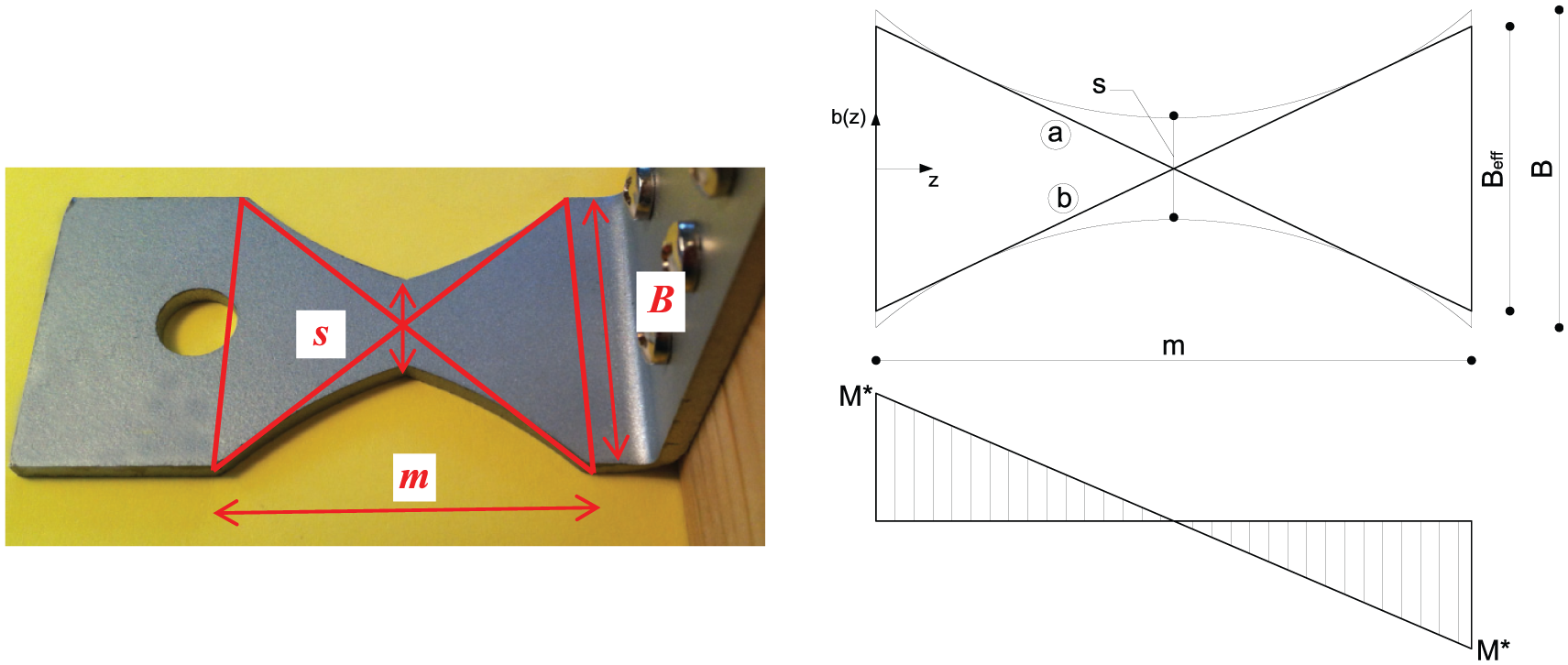
Bending moment diagram arising on the tapered flange of the patented damper: (a) conceptual view of the hourglass region and (b) definition of the notation and bending moment diagram arising on the X-shaped zone.
Starting from the diagram of the bending moment arising in a plate, under the assumption of strong bolt and weak plate, it is easy to verify that the shape which provides the contemporary plasticization of all the plate sections is an X-shape (Figure 2(b)). In the following, the principles at the base of the design of the proposed damper are illustrated as well as the results of a past experimental programme aimed at evaluating the cyclic behaviour of the device. The main results coming from the experimental analysis are reported and compared to that of the classical hold-down system.
The goal of the experimental analysis reported in the next sections is to assess the behaviour of the proposed dissipative angle under the actions normally arising in a typical application of the device to panels’ structures. In particular, the X-shaped angle, analogously to hold-down connectors, in the typical application, is imagined applied at the corners of the vertical panels and, therefore, it is mainly subjected to uni-axial tensile forces. Such tensile actions are usually generated by the rocking motion of the panels which typically activates under seismic actions. The experimental campaign described in the following aims at comparing the behaviour of the classical hold-down connector with the behaviour of the proposed dissipative connector. In particular, the objective is to characterize the behaviour of the angle by means of monotonic and cyclic tests. The planned experimental activity regards five tests: a monotonic test, three cyclic tests at constant amplitude and one cyclic test at increasing values of the amplitude up to failure. The monotonic test is needed in order to characterize the stiffness, resistance and ductility supply of the element, while the cyclic tests are needed in order to evaluate the fatigue life of the element and the cyclic degradation of stiffness at the unloading, peak resistance and energy dissipation supply. The three cyclic tests at constant amplitude are carried out at three different values of the displacement amplitude, so that their results can also be used to evaluate the oligo-cyclic fatigue life curve of the device. All the tests have been carried out at the laboratory of materials and structures of the University of Salerno under uni-axial tensile forces by means of a universal testing machine Schenck Hydropuls S56 (maximum load 630 kN, piston stroke ±125 mm). The tests of the experimental campaign have been labelled and identified with the following identity-tags: AXX (XX is a progressive number which individuates uniquely the test and goes for 01 to 05); M, C or V (identifies the test typology, M stands for monotonic, C stands for cyclic at constant amplitude and V stands for cyclic at variable amplitude) and YY (the second number of the tag identifies the value of the amplitude adopted in the constant amplitude cyclic tests expressed in millimetres). Therefore, the experimental campaign, as already mentioned, has included the following tests: a uni-axial monotonic test (A05-M), three cyclic tests at constant amplitude (A01-C15, A02-C25, A03-C30) and a test at variable amplitude (A04-V).
Adopted design criterion
As already demonstrated in Latour and Rizzano (2012), the behaviour of the AD-XLAM can easily be governed by controlling the values of the main geometrical parameters characterizing the shape of the flange plate, namely, the distance between the bolt and the plastic hinge (m), the width of the plate (B) and the thickness of the plate (t). These three parameters strongly affect the angle’s overall behaviour and, in particular, they influence the initial stiffness, the resistance and the ductility supply of the angle. In particular, as reported in Latour and Rizzano (2012), the initial stiffness of the angle depends on the ratio Bt3/m3, the plastic resistance depends mainly on the parameter Bt2/m and the ductility is governed by the parameter m2/t. Therefore, the shape of the single damper (defined by the parameters B, t and m) can easily be designed as a function of a desired value of the shear capacity of the angle, of the initial stiffness and of the ductility supply. The equations able to control stiffness, resistance and ductility supply to be used in the design process have already been defined in Latour and Rizzano (2012) with an approach based on the full integration of the stress–strain response of the steel composing the angle, leading to the following expressions:
Stiffness

where
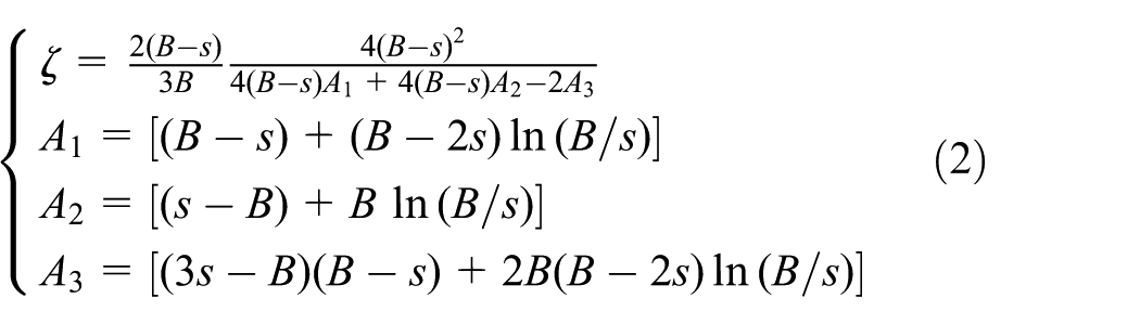
and t is the thickness of the flange plate.
Yield resistance

where fy is the material yield stress and ndampers is the number of dampers used in the angle.
Ultimate resistance

where k is a parameter depending only on the mechanical properties of the steel used to realize the angle; B, s and m are defined as reported in Figure 2; ndampers is the number of hourglass regions used to realize the angle and E and fy are the elastic modulus and yield stress of steel, respectively. As reported in Faella et al. (2000), k for S355 steel class is equal to 3.29.
Ductility supply

where εu is the material ultimate strain.
The specimens tested, whose results are reported in the following, have been designed in order to obtain the same resistance and stiffness of the hold-down tested within the SOFIE project (Gavric et al., 2011). In order to reach this design goal, the geometrical properties of the flange plate have been properly calibrated by exploiting equations (1) to (5).
Monotonic test
The tested specimens consist of a panel of larch with dimension 518 mm × 255 mm × 72 mm on which is fixed, on the top side, a very stiff and strong T-stub and, on the bottom side, a couple of the designed AD-XLAMs (Figure 3). The elements are fastened through eight M12 bolts of 8.8 class. The steel grade of the angles is S275 (CEN, 2005). The connection of the angles to the wood has been designed by following the rules provided by Eurocode 5 (CEN, 2003) in order to have fasteners over-strength with respect to the load carried by the tapered flange plate. In this way, the bearing failure is avoided and the failure of the dissipative zone is promoted. All the tests are quasi-static and in particular they have been conducted under displacement control, with a variable speed from 0.3 to 0.6 mm/s for the cyclic tests with constant amplitude (0.01 Hz), from 0.5 to 0.9 mm/s for the cyclic test at variable amplitude and with a constant speed of 0.025 mm/s for the monotonic test. In addition, coupon tensile tests have been performed in order to establish the mechanical properties of the base material constituting the plates.
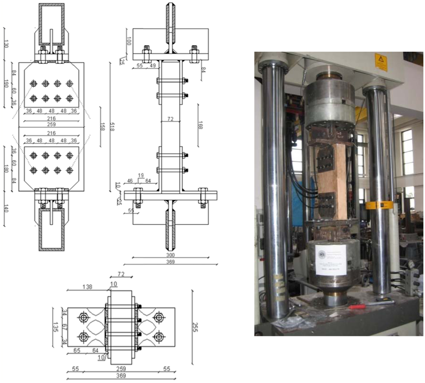
Test set-up.
The monotonic test (A05-M) has been carried out under displacement control at the constant speed of 0.025 mm/s. The test has been stopped because the piston stroke of the universal machine has been reached prior of the failure of the specimen. Nevertheless, the ultimate displacement obtained during the test has been very high and no damage or cracks have been evidenced. As predicted by the FE modelling, the experimental results of the monotonic tests have been very close to the one provided by hold-down tested by Gavric et al. (2011). In fact, the monotonic force–displacement curve has a behaviour which is very similar in terms of force and stiffness to the cyclic envelope of the test on the hold-down of the SOFIE project, but has a higher ductility that is almost two times greater (Figure 4).
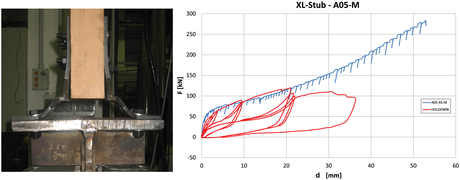
Monotonic test.
As desired in the design phase, all the deformation capacities of the specimen have been concentrated in the flange plate of the AD-XLAM. No wooden or steel part has evidenced damages, but significant second-order effects have been shown. This can also be clearly noted from the force–displacement curve of the angle. In fact, in plastic range, after a first phase of strain-hardening which follows the complete yielding of the plate, there is a slight increase in the stiffness which is due to the catenary effects that arise in the plate. These second-order effects are demonstrated by the plasticization of the stem of the angle in the zone in between the attachment with the flange plate and the first row of bolts.
Cyclic tests
As already underlined, the experimental analysis has been planned in order to verify the possibility to increase the energy dissipation capacity under cyclic loads of classical hold-downs by overturning the classical design philosophy from the nail to the flange plate plasticization. The purpose of the study is comparative. In fact, the basic idea is to show that a dissipative hold-down can be properly designed in order to have a monotonic behaviour very close to that of a classical hold-down but a more dissipative behaviour under cyclic loads.
To this scope, a series of cyclic tests on the AD-XLAM specifically designed for dissipating energy have been planned. In particular, as aforesaid, three constant amplitude tests have been performed with the scope of defining the cyclic behaviour and the fatigue life curve of the element. Fatigue life curve is a powerful tool for carrying out incremental dynamic analysis in order to define the damage and the collapse condition of an element. The displacement amplitudes of the tests, equal to 15, 25 and 30 mm (Figure 5(a) to (c), respectively) have been chosen aiming to cover a range of displacements that are compatible with the typical structural applications to timber panel buildings (Ceccotti et al., 2000). In fact, considering the results of the SOFIE project, under the most severe seismic events considered, the uplift of the hold-down is equal to 25 mm. All the cyclic tests have shown the same collapse mechanism for all the AD-XLAMs.
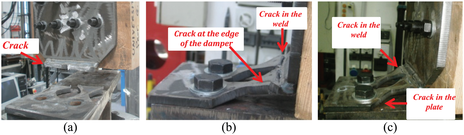
Cyclic tests: (a) test A01-C15, (b) test A02-C25 and (c) test A03-C30.
In Figure 5(a) to (c), the fracture zones have been evidenced for the three cyclic tests reporting an arrow pointing on the plate regions where the crack formation was observed. In particular, in test A01-C15, the failure arose at the welded zone, with the formation of a crack in the top part of the plate that, after few cycles, propagated in the whole plate section leading to the complete failure of the element. In test A02-C25, the failure mechanism was very similar and, therefore, characterized by the formation of a crack in correspondence of the welded section which propagated within the whole plate only few cycles after the formation of the first crack. In test A03-30, the failure occurred, similarly to the other tests, but in this case was also due to the contemporary formation of a crack in correspondence of the bolt section. It is clear that the failure of the AD-XLAM occurs in the welded zone because, even though the angle is ideally designed to have the same resistance in all sections, this is the less resistant region of the plate due to the welding process.
Under cyclic loads, such behaviour gave rise to a progressive deterioration up to failure of stiffness, resistance and energy dissipation capacity. In terms of hysteretic behaviour, the design goal of the angle appears achieved. In fact, the cyclic behaviour in all the three constant amplitude tests is characterized by a very stable response with a low rate of stiffness, strength and energy dissipation capacity degradation before the quick failure due to the development of the crack in the plate (Figure 6). It is evident that the hysteretic response of the developed AD-XLAM is almost unaffected by pinching phenomenon which usually characterizes the behaviour of the classical hold-downs failing in the nails due to bearing. This result is due to the particular shape provided to the flange which leads to a very high dissipative capacity under cyclic loadings. Also, the variable amplitude test has evidenced a satisfactory hysteretic response of the angle under cyclic loads with a large amount of dissipated energy. In fact, the response has been characterized by wide and stable cycles with almost no degradation phenomena up to failure as in cases of tests at constant amplitude. The failure arose after the 42nd cycle at the amplitude of 41.5 mm. In particular, the collapse of the specimen occurred due to the contemporary fracture of the plate in correspondence of the welding and the bolt line. This result has testified again the efficiency of the design criteria of the element which is able to dissipate the external energy by means of the plastic engagement of the whole plate.
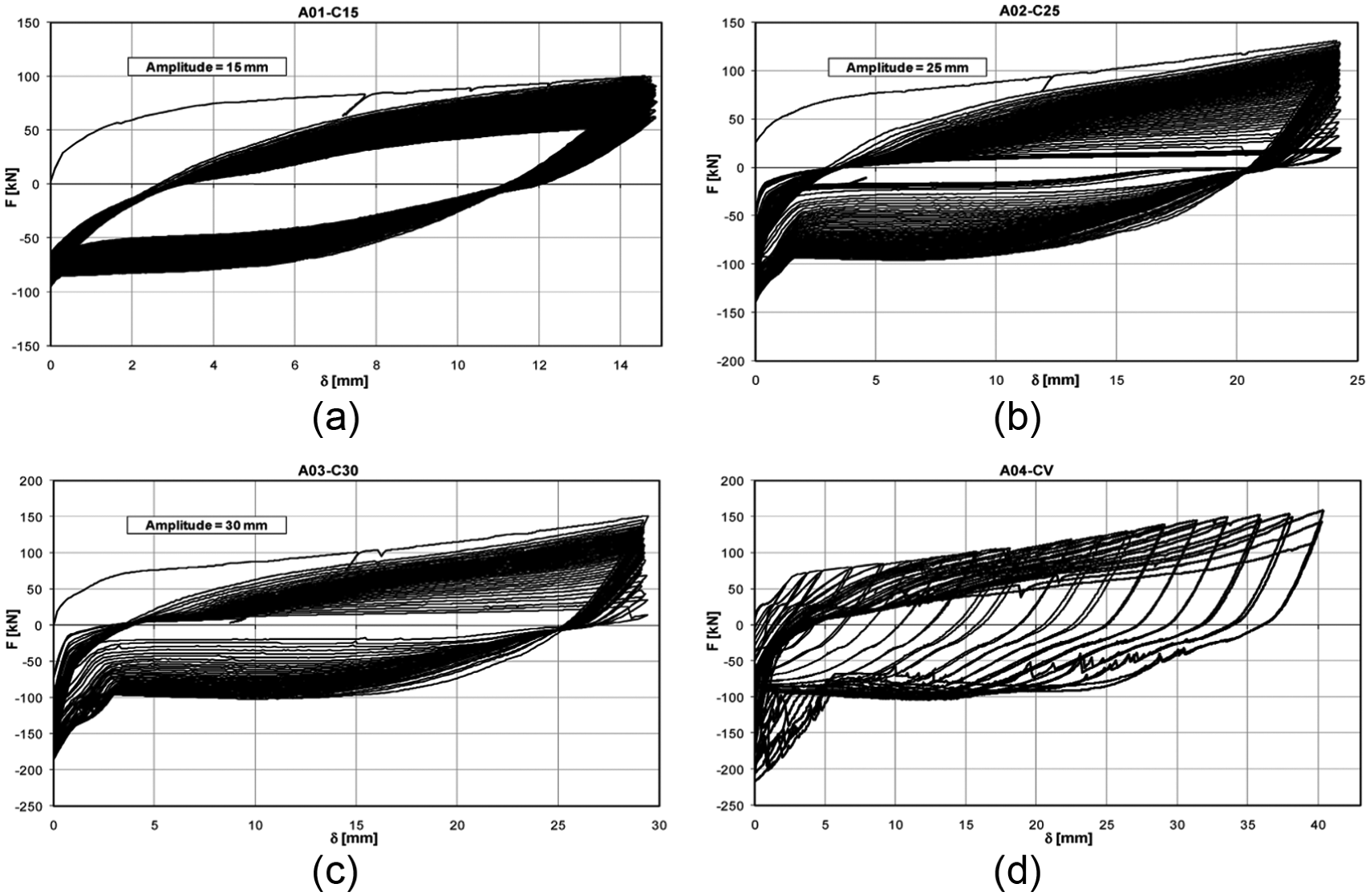
Results of the cyclic tests: (a) test A01-C15, (b) test A02-C25, (c) test A03-C30 and (d) A04-CV.
From the analysis of the response under variable amplitude cycles, it is evident that the angle is able to dissipate an amount of energy that is much greater compared to that of the classical hold-down. In fact, in comparison to the hold-down tested in Gavric et al. (2011), it is possible to observe that, even though the XL-stub has been subjected to a displacement history much more demanding compared to the loading history adopted in the SOFIE project, the cyclic response has been much more stable, dissipative and also with a higher ductility.
In order to better point out the potentialities of the developed system, a direct comparison with the hold-down tested within the SOFIE project has been carried out. In Figure 7, the hysteretic curves of the two details are overlapped in order to grasp the difference in terms of energy dissipation capacity of the XL-stub in comparison with the hold-down. In particular, it is easy to note how the different types of hysteresis of the two elements affect the cyclic response. The hold-down is characterized by significant pinching due to its dissipative mechanism that relies mainly on the plasticization of the nails due to bearing. In fact, as already said, at the reversals the nails have to slip into the deformed holes before restoring the force. It is for this reason that after unloading, at the re-loading the hysteretic curve is characterized by a first branch that is almost horizontal due to the nail slippage and a second branch with a significant increase in stiffness and energy dissipation (Figure 7). On the contrary, the XL-stub shows a behaviour that is much more dissipative due to the shift of the mechanism of plasticization from the stem to the plate. In addition, the particular hourglass shape of the plate provides a high dissipative capacity that is demonstrated by the comparison of the amount of energy dissipated at collapse.

XL-stub versus hold-down.
Design of different solutions of the AD-XLAM alternative to the classical hold-down
As aforesaid, the basic idea of the proposed device is to shift the dissipative zone from the nails to the flange plate, by over-strengthening the stem plate and by weakening the flange plate according to an X-shape. In order to carry out a comparison between a typical hold-down used in the current practice and the proposed damper, the design of four different solutions equivalent to a typical hold-down used in the current practice has been carried out. The reference hold-down is the one reported in Hoekstra (2012a, 2012b), which is composed by a bended plate of thickness of 3 mm with stiffeners and backing plate, fixed to the wood by means of 50 nails. In particular, in order to show the strong adaptability of the proposed system, four different solutions have been designed in order to have all the same ultimate resistance and displacement capacity (the same resistance of the hold-down, that is, about 100 kN and a ductility five times greater, that is, 50 mm), but a variable thickness of the flange plate (from 15 to 7 mm) and a variable number of dampers, which increases from one to four at the decrease in the plate thickness. In fact, the patented system allows a great flexibility in the design phase because by varying the width, length, thickness and number of dampers, it is possible to govern easily stiffness, resistance and ductility supply. As an example, starting from the previously reported equations for the prediction of stiffness, resistance and ductility supply, it is very easy to provide the following design equations, able to define the geometry of the plate provided that thickness, design force and the displacement capacity are fixed

where the notation of equation (6) is the same already introduced in Figure 2 and for equations (4) and (5). Following the design criterion previously reported, four elements characterized by different thickness values (15, 10, 8 and 7 mm) have been designed, obtaining different values of the number of dampers and the geometrical properties of the single damper (Table 1). It is worth noting that by following the design criteria illustrated, the elements could easily be designed in order to also obtain a higher or lower value of the resistance or a higher value of the ductility. This is a great advantage of the patented system, because it is ideally possible to calibrate the geometry of the dampers in order to obtain fixed values of the resistance maintaining high values of the ductility supply.
Characteristics of the designed angles.
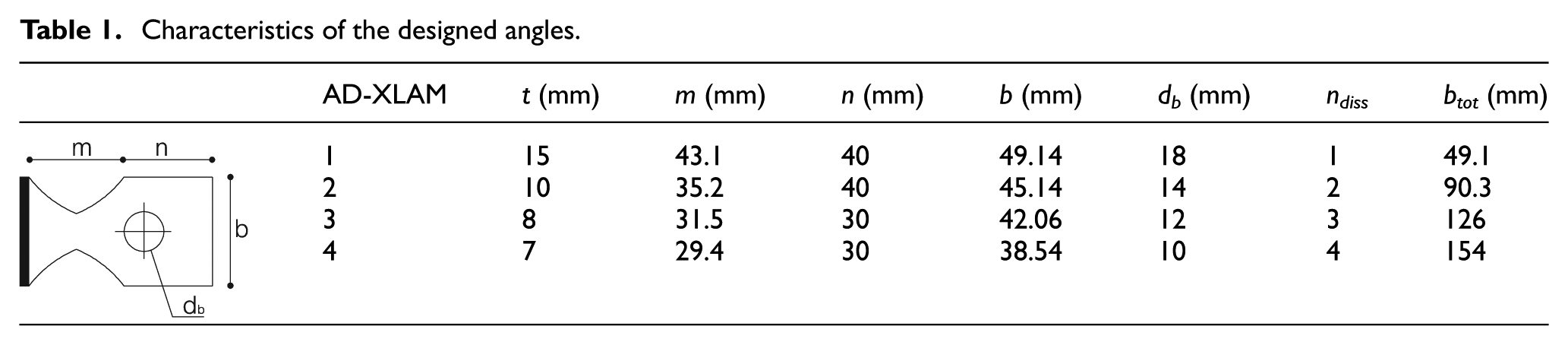
In the table, the dimensions of the dissipative angles designed are summarized reporting the number of dampers, thickness and width of the plate. In addition, in Figure 8, a rendering of the angles is depicted. It is useful to note that the thickness of the stem plate of the angle is hypothesized equal to the thickness of the stem of the classical hold-down (3 mm). In order to show the different properties of classical and innovative system and, in order to show the accuracy of the design procedure, in the following the FE modelling of the classical hold-down and the four angles previously designed is carried out.
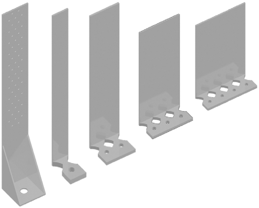
Rendering of hold-down and dissipative angles.
FE modelling of the hold-down
In order to provide an effective comparison between the behaviours of the classical hold-down and the proposed dissipative angle, FE modelling of the hold-down and of the AD-XLAM has been developed. To this scope, the hold-down reported in Hoekstra (2012b) is modelled. Such a hold-down, as previously reported, is characterized by a flange plate of thickness equal to 3 mm, fixed with 50 nails and a stiffening plate with 20 mm of thickness. This hold-down is characterized by a resistance of 102 kN and an ultimate displacement of 10 mm.
In order to set up the FE model, the following steps are necessary: geometrical definition of the elements, modelling of the materials’ properties, definition of the interactions arising between the elements, definition of the boundary conditions, choice of the element type and mesh size. The goal is to define a solid three-dimensional model. The model is constituted by three elements: the angle, the stiffening plate and the support (Figure 9). The geometries of such parts have been generated by means of the modelling tools available in ABAQUS. In particular, all the elements have been defined through extrusion of their cross section. The materials’ properties have been described by means of an elastic–plastic isotropic model, by adopting the quadri-linear approximation described in Latour et al. (2014) (Figure 10).

Parts of the hold-down FE model.

Quadri-linear approximation for the steel behaviour (Latour et al., 2014).
Concerning the element type, an eight-node linear brick with reduced integration and instability mesh control has been adopted (C3D8R). The choice of this type of element comes from the following considerations: first of all, aiming to reduce the computational effort, a first-order element (linear brick) has been chosen, taking into account that, although second-order elements provide higher accuracy, in the presence of complicated phenomena, such as contacts and slips, the computational effort grows significantly. Therefore, in order to reduce the processing time, a ‘reduced integration element’, using a lower order integration has been adopted. In particular, in case of eight-node bricks, the integration points are reduced from eight to one leading to a much lighter model. This choice does not reduce the accuracy of the analysis, provided that an instability mesh control is simultaneously applied. In fact, reduced integration elements can exhibit some kind of mesh instability such as the hourglassing (Kosloff and Frazie, 1978), which is a special case of the phenomenon known in FEs as kinematic modes or spurious zero-energy modes. Practically, since the elements have only one integration point, it is possible for them to distort in such a way that the strains calculated at the integration points are all 0, leading to the uncontrolled distortion of the mesh. In order to avoid this phenomenon, the viscous approach of ABAQUS code has been employed in the FE modelling.
The mesh size has been defined by carrying out a sensitivity analysis in the preliminary phase, by accounting also for the existing guidelines on the topic. In particular, in the work of Hongxia et al. (2008), a detailed discussion is reported. In case of connections, the following mesh size effects have to be preliminarily evaluated: the number of elements through the thickness of the flange and number of elements to be introduced in the contact zone. Therefore, in order to obtain accurate results, the following meshing procedures have been respected: the T-stub flange plate has been meshed with a minimum size of the elements of 5 mm and at least two elements within the thickness of the plate; the rigid and strong plate of the support has been meshed with elements with maximum size of 15 mm. Furthermore, all the parts have been partitioned in order to allow the definition of structured meshing techniques, leading in this way to stable results and good convergence of the model.
‘The interaction among the various elements has been defined according to a surface-to-surface formulation with finite sliding. In the normal direction a hard contact’ has been used, while in the tangential direction a friction coefficient equal to 0.2 has been adopted. The following interactions have been introduced in the model: interaction between the T-stub lower face and the rigid support upper face and interaction between upper face of the flange plate and rigid plate.
The FE model has been analysed by means of a static non-linear analysis also considering second-order effects. The geometric non-linearity has been properly accounted for in order to grasp the full post elastic behaviour of tested T-stubs, which can be characterized, at large displacements, by considerable second-order effects due to axial stiffness of the plate or the slip of the bolts in the holes. In an approximate way, the nails and the anchor bolt have been modelled by introducing simple constraints in correspondence of the holes. The load has been applied, by introducing in correspondence of the holes a displacement of 15 mm (Figure 11).
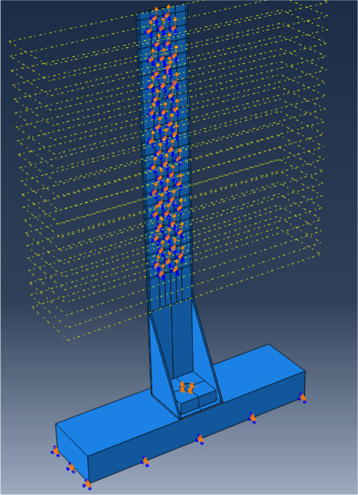
FE model of the hold-down.
The accuracy of the proposed model is evaluated by comparing the results of the simulation with the results of the experimental tests reported in Hoekstra (2012b). The qualitative comparison of the deformed shape of the FE element model with the experimental test results shows that the FE model is able to accurately reproduce the deformed shape observed in the experimental test. In addition, the failure zone seems very well individuated, and in the same way the concentration of stresses in this portion (Figures 12 and 13).

FE model – von Mises stresses.

Yielded zones at failure.
Furthermore, the comparison of the experimental and FE curves shows that the proposed model is able to simulate accurately the ultimate force of the device, while some approximations are observed with respect to the prediction of the stiffness. The overestimation of the model is mainly due to the approximations made in the modelling of nails and in the modelling of the anchor bolt in tension. In fact, both nails and anchor bolt in tension, as also provided by international codes (CEN, 2003, 2005), can influence the response plates in bending (angles or T-stubs), increasing significantly the deformability of the element. In order to include these aspects also in the model, appropriate shear or tension springs should be calibrated and introduced in correspondence of the web and flange of the hold-down. Nevertheless, as far as the prediction of stiffness is out of the scopes of this work, which mainly focuses on the prediction of resistance, this approximation is considered acceptable (Figure 14).
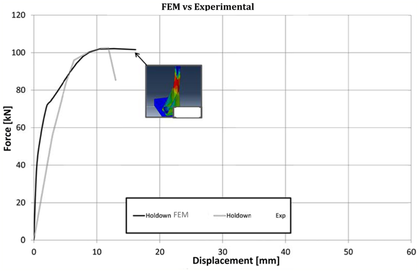
FEM versus experimental.
FE modelling of the AD-XLAM
For the four dissipative angles designed, the FE modelling has been carried out analogously with respect to the previous case, by employing the same methodology, the same mesh subdivision, the same type of interactions and the same type of constraints (Figure 15). Also in this case, in all the analysed cases, the obtained results are very satisfactory and in agreement with the behaviour expected in the design phase, both in terms of resistance and ductility supply. In fact, as it is possible to observe from the FE model, the deformation capacity is mainly concentrated in the dissipative angle, without the development of significant plasticization out from the carved zone.
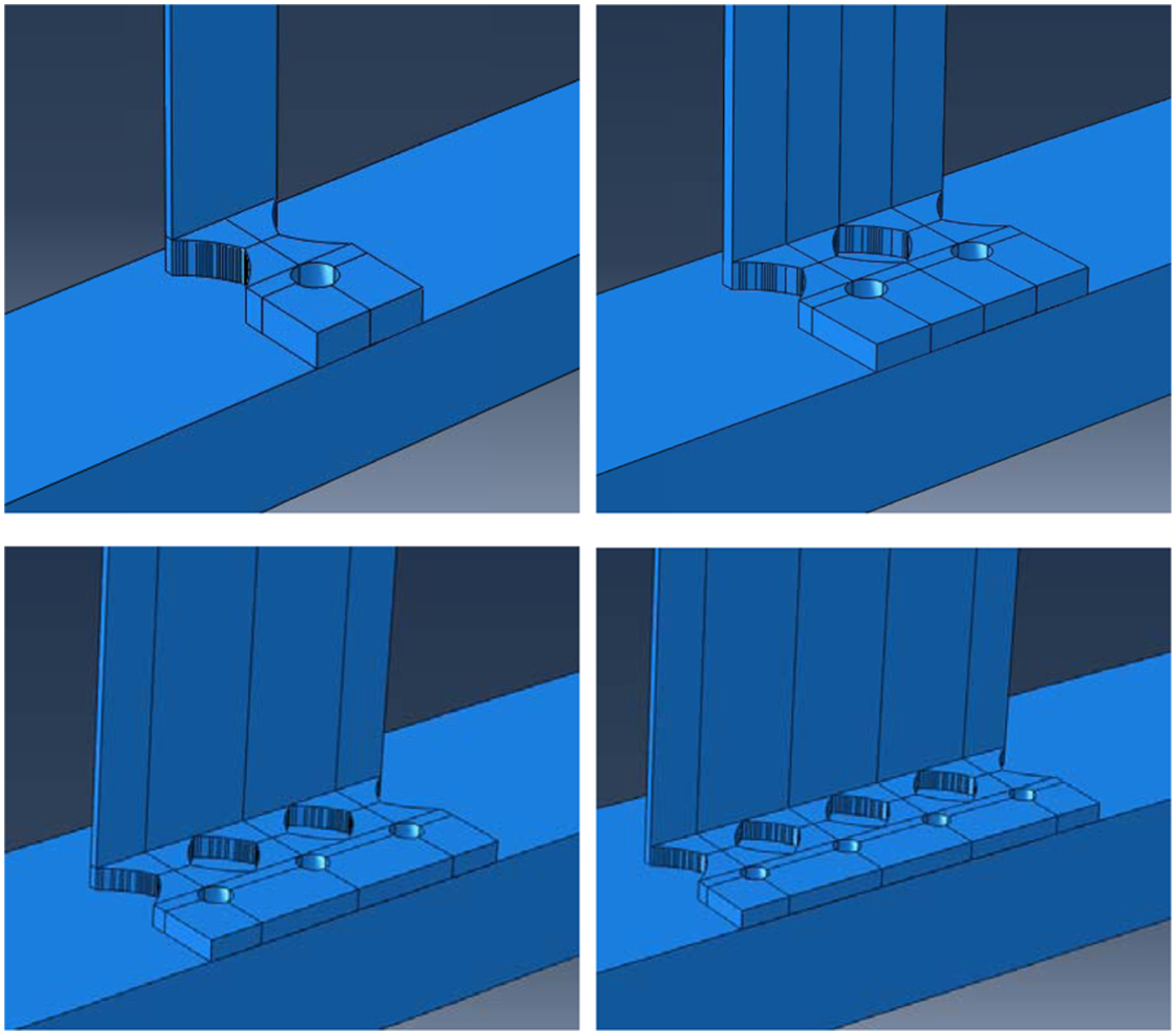
FEM of the AD-XLAM.
Some of the results of the analyses are reported in Figures 16 to 18, where the main characteristic of the proposed dissipative angle are shown, namely, the high ductility and the capacity to spread the plasticization within the whole flange plate of the angle.
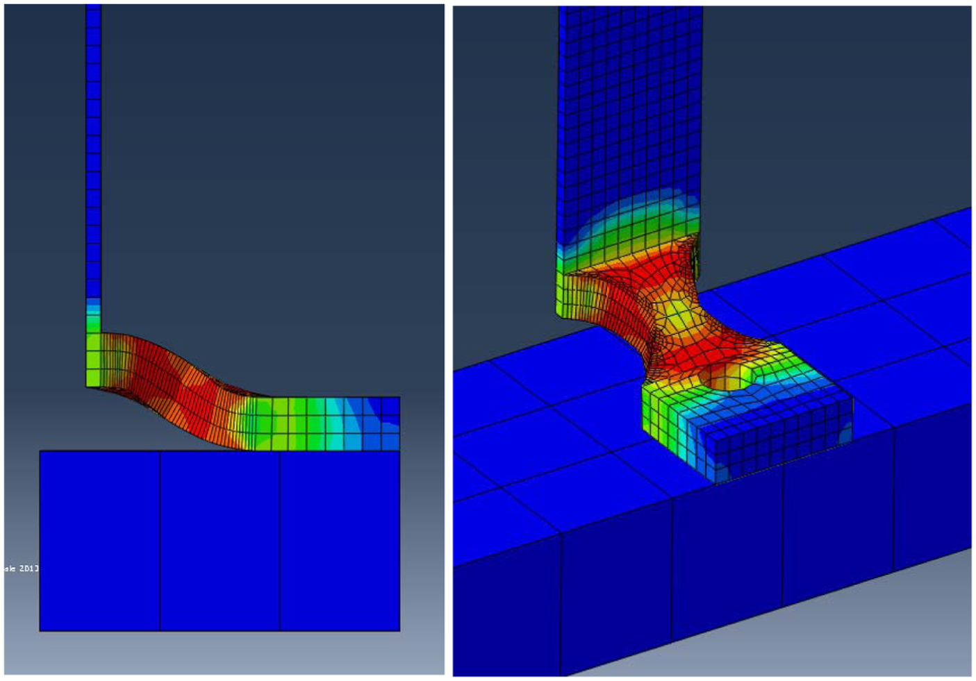
von Mises stresses and deformed shape (15 mm).
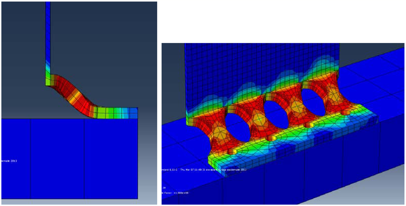
von Mises stresses and deformed shape (7 mm).
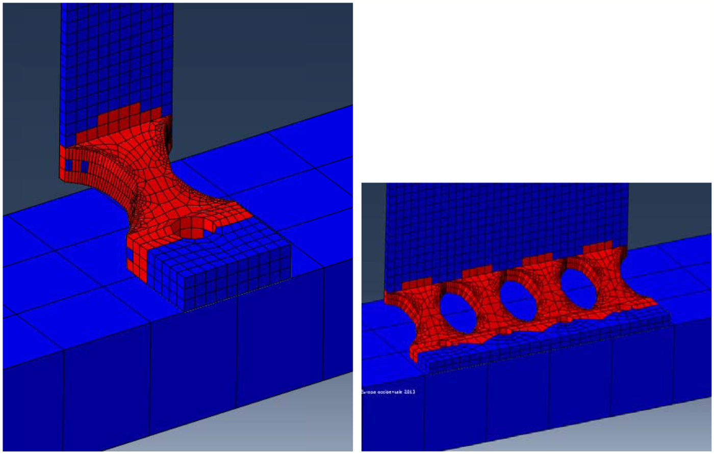
Yielded zones (AD 15 and 7 mm).
The results of the simulations in terms of force–displacement curve confirm the accuracy of the design procedure reported in the previous paragraph. In fact, the ultimate resistance and the ultimate displacements are equal to the values hypothesized in the design phase (Figure 19).
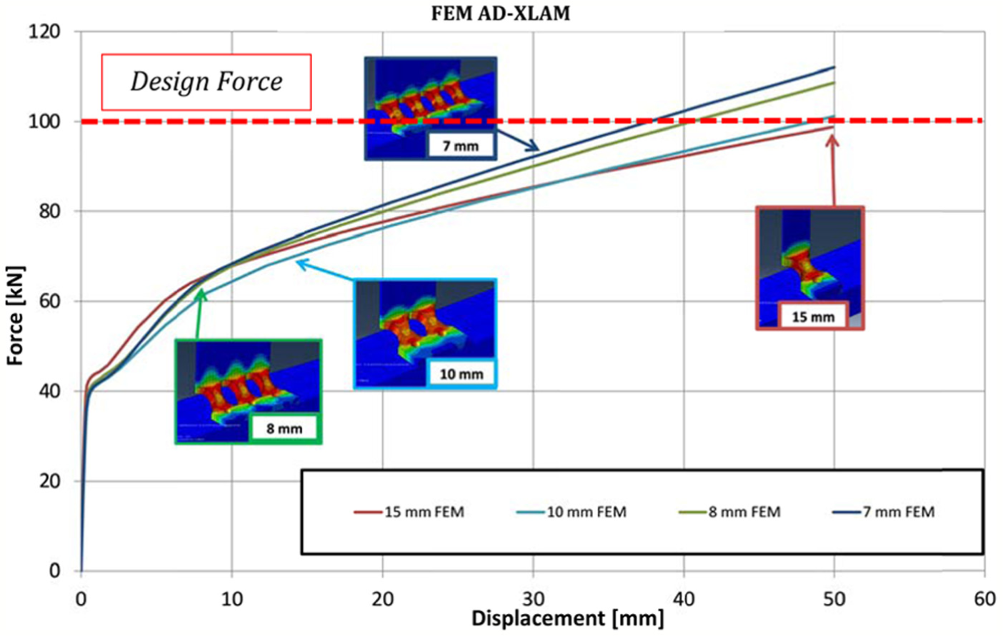
FEM simulation of the AD-XLAM.
In Figure 20, the comparison between the behaviour of the hold-down and the behaviours of the different types of AD-XLAM is delivered. From such a figure, it is possible to observe that the resistance and the stiffness of the AD-XLAM are largely equal to the resistance and stiffness of the corresponding hold-down. The comparison shows the different behaviour of the two elements. In particular, the hold-down is characterized by a very limited ductility, while the AD-XLAM is characterized by a very large ductility, which is the reason why it is able to develop a high-energy dissipation supply under cyclic loads.
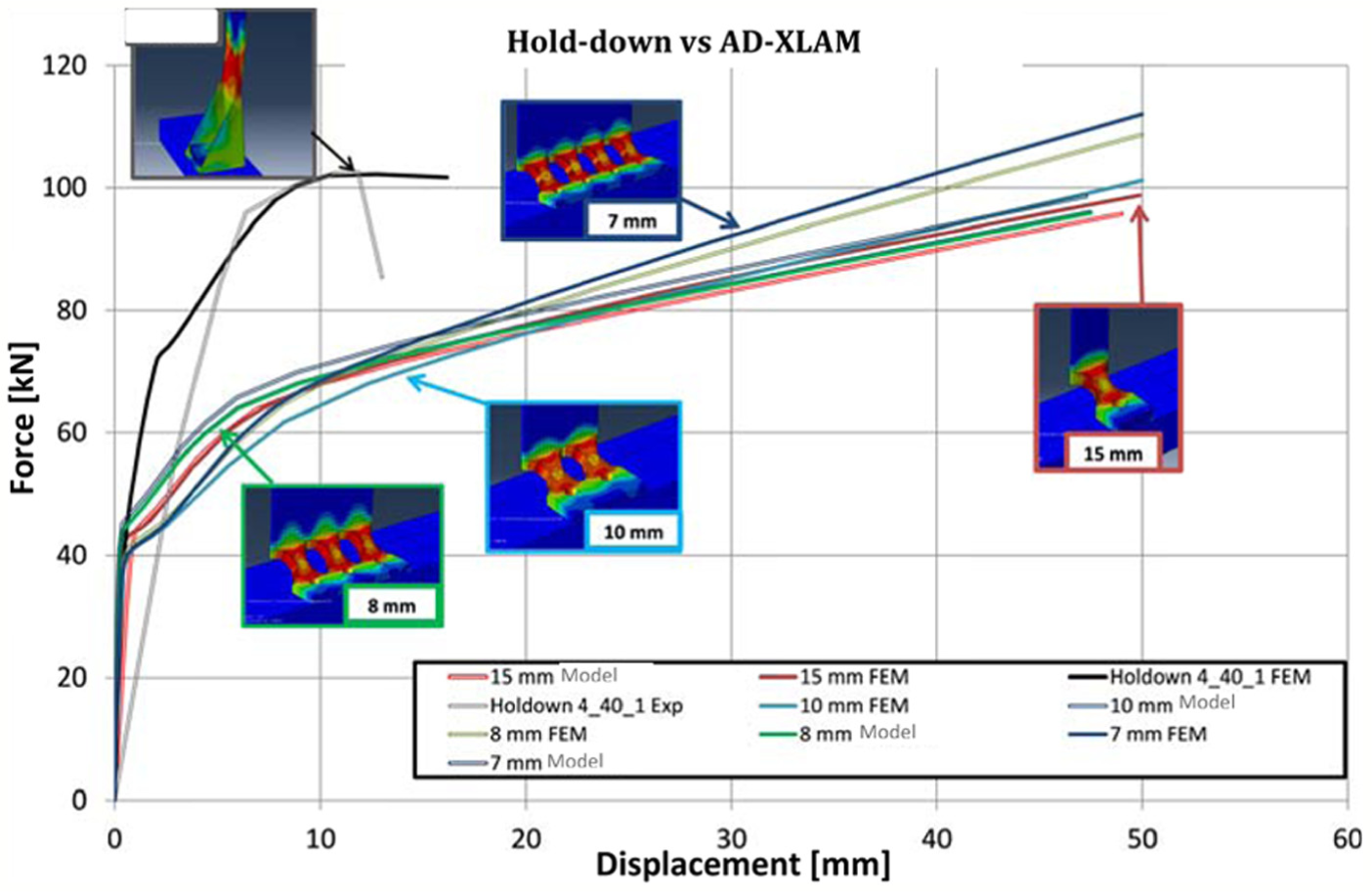
AD-XLAM versus hold-down.
Cost comparison
In this section, a preliminary estimate of cost and weight of the elements composing the classical hold-down and the proposed AD-XLAMs is reported. The manufacturing process of the hold-down requires the following procedures:
Realization of the stem, flange and stiffeners of the hold-down by means of punching, starting from the same plate;
Bending of the flange plate and of the stiffeners;
Welding of the stiffeners on the stem;
Production of the stiffening plate with thickness equal to 20 mm to be applied on the flange plate of the angle, by means of laser or oxy-fuel cut.
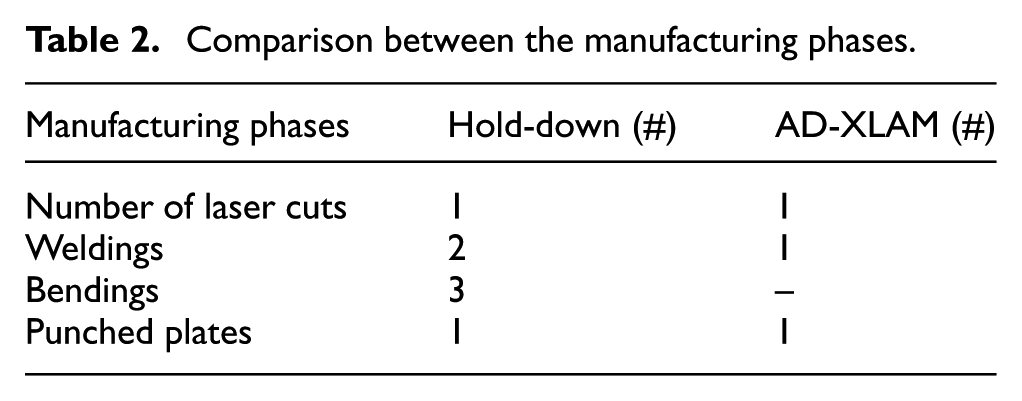
Conversely, the AD-XLAM requires the following manufacturing process (Table 2):
Comparison between the manufacturing phases.
Laser cut of the flange plate of the dissipative angle, comprehensive of the carved portions according to the shape defined in the design process;
Punching of the stem plate;
Welding of the stem and flange plates.
Therefore, by comparing the manufacturing phases of the two elements, it is easy to understand that the phases needed to realize the AD-XLAM are less and simpler; in fact, no bending of the parts is required and the length of the welds is lesser.
Regarding the weight of the steel to be employed in the manufacturing, the stem plates of hold-down and AD-XLAM are the same, considering that the stem is practically already over-resistant with respect to the resistance of the dampers. Regarding the weight of the steel to be employed for the flange plate of the hold-down, the following steel elements have to be considered in the cost estimate:
Flange plate 80 mm × 80 mm × 3 mm;
Two stiffeners 150 mm × 80 mm × 3 mm;
Stiffening plate 75 mm × 75 mm × 20 mm.
Conversely, for the proposed dissipative angles, for the four different cases, in order to evaluate the weight of the flange plate, it is necessary to evaluate the weight of the plate circumscribing the flange plate in order to consider also the cost of the carved portion of the plate. Therefore, the weights of the flange plates for the different solutions are given in Table 3.
Weight of the steel needed to manufacture the flange plate.
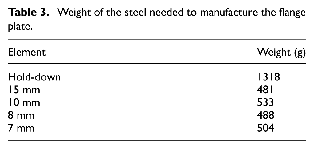
From Table 3, it is possible to observe that for all the adopted solutions, the weight of the flange plate is always lesser than the corresponding weight needed to realize the hold-down. Furthermore, it is possible to observe that the weight of the flange plates of the AD-XLAMs varies in the range in between 481 and 533 g and, therefore, it is equal to about one-third of the weight of the flange plate of the hold-down. In addition, the solution with the single damper and thickness of 15 mm is the lightest solution. This analysis demonstrates the double advantage that is possible to obtain with the proposed system. In fact, the AD-XLAM is characterized by higher performances under cyclic loading conditions and a lower cost of the element. This result appears very promising in order to propose the patented device for an industrial application.
Conclusion
In this work, the results of an analysis regarding the behaviour of a device recently patented have been presented. In particular, the analysis has been carried out on different levels in order to demonstrate the industrial applicability of the proposed system to the construction market. The experimental and numerical analyses have been carried out and cost issues have been considered in order to define the differences between the classical and innovative systems both in terms of performances and cost needed to manufacture the element. The proposed angle can be used in all the cases where it is needed to rely on dissipative fuses in order to increase the energy dissipation and to increase, as a consequence, the structural damping of the structure. Immediate implications of the proposed technology can be individuated in all the applications where currently hold-downs are employed. Among these, CLT housing system and light-gauge steel panel system can be seen as a more easy application for the proposed angle. In fact, in the CLT panel buildings, the proposed dissipative angle can be introduced easily at the corners of the single panels in order to dissipate the seismic energy working on the rocking motion arising under seismic loading conditions. In a similar way, the AD-XLAM could also be applied to light-gauge structures, where it could be introduced easily in substitution of the hold-downs at the intersections between vertical studs and horizontal beams.
The main conclusion of this work can be summarized as follows:
The patented AD-XLAM is characterized by a hysteretic behaviour with wide and stable hysteresis loops. Its ability of dissipating energy under seismic actions is much greater than the energy dissipated by an hold-down with same resistance and stiffness.
The proposed system is appropriate for an industrial application, as far as its behaviour can be easily controlled in terms of resistance, stiffness and ductility supply by varying the shape and/or number of dampers.
The FE element models and the comparison with the experimental results have demonstrated that the numerical simulation is a tool appropriate for the prediction of the force–displacement behaviour of these connectors.
The FE models have also revealed that the resistance and ductility of the designed elements can easily be predicted by means of the proposed design approach.
The cost analysis has revealed that the proposed damper is not only able to provide higher performances but it is also cheaper than the classical hold-downs.
Footnotes
Declaration of Conflicting Interests
The author(s) declared no potential conflicts of interest with respect to the research, authorship and/or publication of this article.
Funding
The author(s) received no financial support for the research, authorship and/or publication of this article.