
Abstract
This article presents theoretical responses and the results of finite element analysis of seven beam specimens in an interior post-tensioned steel semi-rigid beam-to-column connection including the corrugated webbed beams under the earthquake simulated by cyclic loading up to 4% story drift using well-known software ABAQUS. The connections include the bolted top and bottom angles to dissipate the input energy and high-strength steel strands passed parallel to the beams to provide the post-tensioning force which compresses the beam flanges against the column flange. The finite element results showed that using beams with thinner corrugated web and thicker flanges instead of traditional wide flange beams in post-tensioned semi-rigid connections is more economical in addition to the same bending strength. The inelastic deformations concentrated in the connection angles provide energy dissipation, while no damage affects the beams and columns, and the elastic strands return the frame to its initial position before the earthquake.
Keywords
Introduction
Despite the high cost, structural steel is one of the favorite materials for constructing buildings due to excellent properties such as significant strength and ductility. The Northridge earthquake in 1994 led to failure of many welded beam-to-column connections in steel moment-resistant frames (MRFs); after that earthquake, several researches have been carried out to improve welded connections and have resulted in some modified welded connection details. All these modified details have been considered to develop plastic deformations in the beam at a short distance from the connection to prevent damage to the connection, but permanent residual deformations after the earthquake lead to high repair costs.
In order to eliminate these damages, some researchers have proposed various new post-tensioned (PT) beam-to-column connections for steel MRFs using high-strength steel strands or bars passed parallel to the beam to apply post-tensioning force. Ricles et al. (2002) and Garlock et al. (2005) used the bolted top and bottom angles as energy dissipators that can be easily replaced; this type of connection made by conventional materials and skills does not require field welding; also, the initial stiffness of the connection is similar to that of a typical welded connection and the connection has self-centering capability without residual deformation after an earthquake. Christopoulos et al. (2002) proposed energy dissipating bars in order to yield in tension and compression which are confined by the steel cylinders welded to the interior surface of beam flanges and this energy dissipation device has no interference with the concrete slab and provides good level of energy dissipation and the connection remains damage-free under the design earthquake; however, more analytical and experimental studies should be conducted to reach full understanding of the behavior of steel structures with these connections under seismic loadings. Rojas et al. (2005) used brass–steel surfaces in the friction devices set up on the beam flanges to dissipate the input energy; there is no field welding in this kind of connection made by conventional materials and skills; moreover, the MRFs with this type of connections does not suffer from residual story drift after an earthquake; on the other hand, this system does not necessarily result in reduced drift in comparison with the MRFs including standard fully restrained welded connections. Kim and Christopoulos (2009) applied special friction devices placed at the beam flanges to dissipate energy, a steel cover is used to avoid the interference of the friction device with the floor slab, and the connection has the capability to develop similar stiffness and strength to a fully restrained welded connection and undergo large deformations with reliable energy dissipation characteristics within self-centering limit and show the ductile behavior without sudden loss of strength at extreme loadings. Wolski et al. (2009) used a friction device that is only located at the beam bottom flange as an energy dissipator; this device provides predictable, repeatable, and consistent energy dissipation without undergoing any damage under the design earthquake, whereas the flexibility of the leg of the column angle connecting the friction device to the column causes reduction in the energy dissipation of the device under load reversal. Vasdravellis et al. (2013) proposed new energy dissipation devices shaped like hourglass and installed between the beam flanges without interference with the concrete slab; this connection results in the elimination of beam damage and residual drift up to 6% drifts, but the cost of manufacturing the connection is relatively high. In the above-mentioned researches, PT beam-to-column connections in the MRFs result in no damage to beams and columns during the design earthquake; also, post-tensioning force provided by PT strands or bars returns the MRFs to their initial position.
Furthermore, I-section beams with flat web are widely used in steel buildings. In this kind of beams, the flanges and web contribute to carry external loads in the way that the beam flanges resist greater part of the bending moment and the beam web, that has considerable share to the total weight of the beam, resists most of the transverse shear force. In order to save steel economically without diminishing the beam capability in carrying loads, it is practical to use thinner web and thicker flanges instead of traditional wide flange beams; also, applying corrugated web instead of flat web in I-beams boosts the web shear buckling strength without introducing transverse stiffeners; in other words, the construction costs of steel buildings are remarkably decreased using the corrugated webbed beams.
Many investigations on the behavior of steel corrugated webbed beams have been carried out. Elgaaly et al. (1997) and some other researchers considered the criteria of beam flange yielding to calculate beam bending capacity and ignored any corrugated web contribution to carry bending moment, but Kim et al. (2011) analytically and Kim and Lee (2011) experimentally showed that the contribution of the corrugated web to flexural and axial rigidities can be estimated by calculating the factors of the effective moment of inertia and the effective web area, respectively. Abbas et al. (2006) showed that the conventional beam theory can only be used to analyze the in-plane bending behavior of the corrugated webbed beams and the flange transverse bending analysis is needed to determine the out-of-plane torsional behavior. Also, investigations by Lindner and Aschinger (1988) showed that the effect of the interaction between local shear buckling and global shear buckling must be considered. In this article, the behavior of the corrugated webbed beams in steel MRFs including PT semi-rigid beam-to-column connection has been investigated in which the bolted top and bottom angles are used as energy dissipators and high-strength steel strands are applied to provide post-tensioning force. In order to study the advantages of using the corrugated webbed beams instead of traditional I-beams in PT semi-rigid connections, six specimens of the corrugated webbed beams with less weight than a specimen with the wide flange beam (W36 × 160) have been considered.
Behavior of corrugated webbed beams in PT semi-rigid connections
In order to theoretically analyze the behavior of the corrugated webbed beams in the PT semi-rigid beam-to-column connection, the detail of the PT connection has been selected from that suggested by Garlock et al. (2005) as shown in Figure 1(a). This connection includes the bolted top and bottom angles as energy dissipators and seven-wire ASTM A416 high-strength steel strands to make the beam flanges compressed against the column flange, so the compression provides initial resistant moment called decompression moment. In addition, the arrangement of steel strands should make the strands centroid at the beam–column interface symmetrically set at the beam centroid. Sample MRF with the PT connections is shown in Figure 1(b).
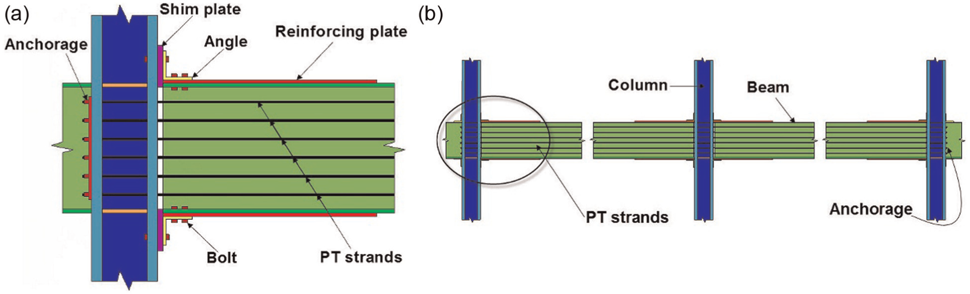
(a) PT semi-rigid connection details and (b) steel MRF with PT semi-rigid connections.
Flexural behavior of PT semi-rigid connections
Overall behavior of a PT semi-rigid connection is characterized by idealized normalized moment–relative rotation relationship (M/Mp,n − θr), where Mp,n is the nominal plastic moment capacity of the beam, and θr is the relative rotation at the beam–column interface as shown in Figure 2(a). The series of events demonstrating the behavior of the PT connection are as follows: the gap at the beam–column interface opens after overcoming the decompression moment (event 1). The initial stiffness of the connection is the same as that of a welded moment connection until decompression; after this point, it is associated with the stiffness of the angles and the post-tensioning strands. With continued loading, the tension angle yielding occurs (event 2). Afterward, yield mechanism of the angle occurs (event 3) which is formed with three plastic hinges in the angle (Garlock et al., 2003); the connection stiffness between this point and the unloading point before the yielding of strands (event 4) is associated with the elastic stiffness of the strands and the deformation hardening of the angles. With unloading at event 4, the energy is dissipated by the angles until the gap is closed at the interface (event 7). If the reverse loading and unloading are applied to this system, the same behavior occurs (events 0, 8–14). The deformed PT connection after decompression is shown in Figure 2(b).
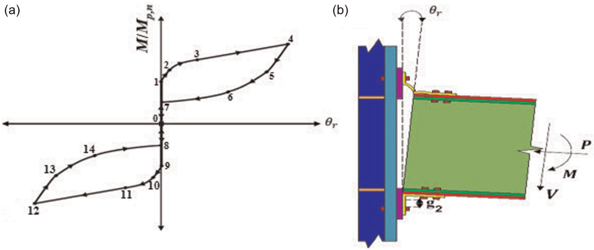
(a) Normalized moment–relative rotation relationship and (b) deformed PT semi-rigid connection after decompression.
Gap opening occurs when bending moment exceeds the decompression moment Md,th which can be estimated by (Ricles et al., 2002)
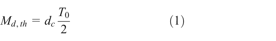
where T0 is the sum of the initial post-tensioning force and dc is the distance between the centroids of contact areas that is twice the distance between the beam centerline and the centroid of contact area (2d2). Ricles et al. (2002) estimated θr shown in Figure 2(b) at the story drift θ as follows
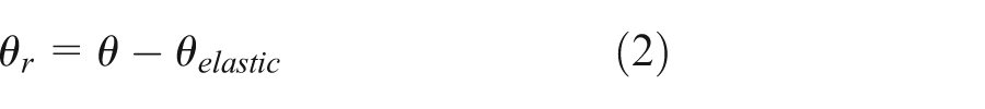
where θelastic is the story elastic drift which results in elastic deformations in beams, columns, and panel zones. Ricles et al. (2002) proposed an elastic frame analysis with rigid connections to estimate the elastic drift. Garlock (2002) estimated the total force developed in the post-tensioning strands after decompression Tth due to the elongation of strands which causes an increase in the force of strands and beam shortening
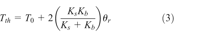
where Ks is the axial stiffness of the strands, and Kb is the axial stiffness of the beam. Free body diagram shown in Figure 3 is used to analyze the behavior of the PT connection. After the yield mechanism occurs in the tension angle, the angle shear force Va developed at the plastic hinge of the column leg of the tension angle with a distance of d1 from the center of rotation as shown in Figure 3 can be calculated as follows (Garlock et al., 2005)
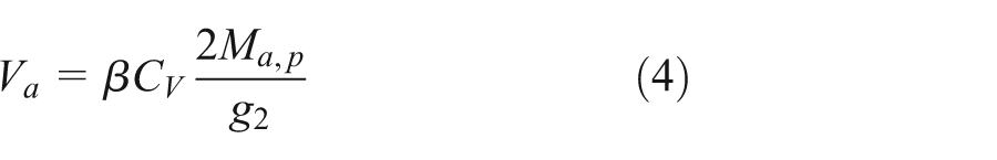
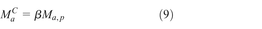
where Ma,p is the plastic moment capacity of the angle leg, and g2 is the gage length of the angle as shown in Figure 2(b); β is the overstrength factor due to the hardening of steel material and geometric, and CV is the influence factor due to the angle thickness that can be calculated as follows, respectively (Garlock et al., 2005)
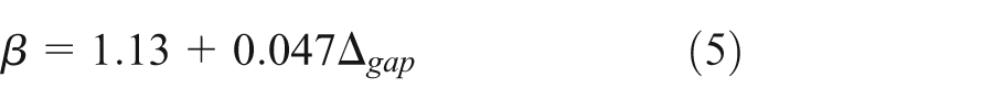
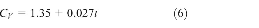
where t is the angle thickness (mm), and Δ gap is the gap opening at the beam–column interface (mm) estimated by Δ gap = θrd3 (Garlock et al., 2005) in which d3 is the distance from the center of rotation to the centerline of tension angle leg as shown in Figure 3.
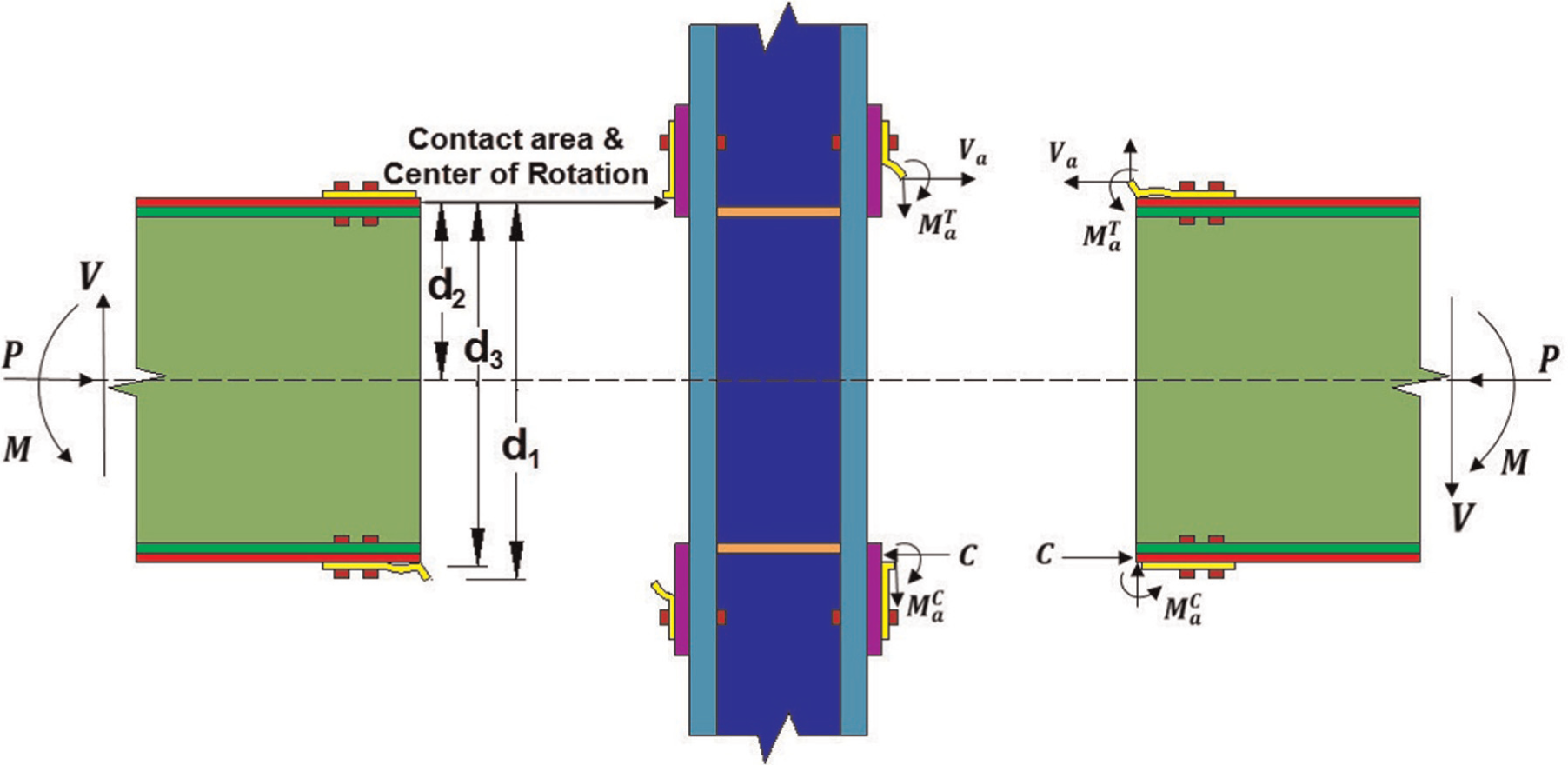
Free body diagram of an interior PT semi-rigid connection.
Garlock et al. (2005) assumed that the contact force C acts at the center of rotation and showed that the center of rotation is at the center of reinforcing plate; therefore
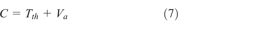
Bending moment at the beam–column interface Mth can be predicted as follows (Garlock et al., 2005)
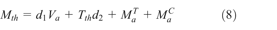
where
The sectional area of the beam reinforcing plates Arp must be satisfied in equation (11) to prevent beam inelastic deformations under bearing stress at the beam–column interface (Garlock et al., 2005)
where σrp,y is the yield strength of the reinforcing plate, and Cf,y is the force that causes beam flange yielding. Garlock et al. (2007) used equation (12) based on the beam horizontal shear yield to calculate the reinforcing plate length Lrp
where τw,y is the shear yield stress of the beam web. In order to prevent local buckling of beam flanges, Garlock et al. (2005) recommended that the reinforcing plate length should keep the beam flange strains under two times the yield strain.
Behavior of corrugated webbed beams
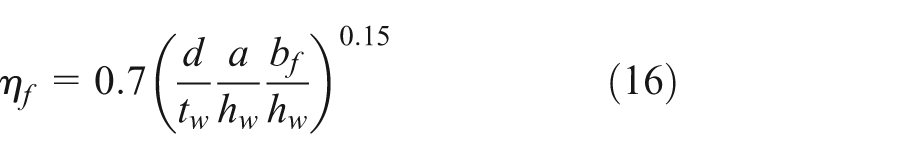
Corrugated webs considered in this study include modification near the PT beam-to-column connection which has the same length as the longitudinal part width that reduces the distance between the connection and the first corrugated part; furthermore, the corrugated web of specimens have the same height as the web of W36 × 160. The corrugated web parameters shown in Figure 4 are defined as follows: a is the longitudinal part width, b is the horizontal width of the diagonal part, c is the diagonal part width, d is the wave depth of the corrugated web, hw is the web height, and tw is the web thickness.
Corrugated web configurations.
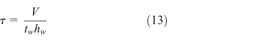
On the assumption that the beam flanges have no contributions in carrying the primary shear force V and it is completely carried by corrugated web constant shear stress of the beam web τ can be calculated as follows
Flexural behavior
Accordion effect in I-section beam with the corrugated web makes the flanges carry most of primary bending moment and the web has small contribution; Kim et al. (2011) used effective moment of inertia Ieff and effective sectional area Aeff for calculating flexural rigidity and axial rigidity, respectively
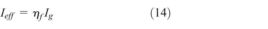
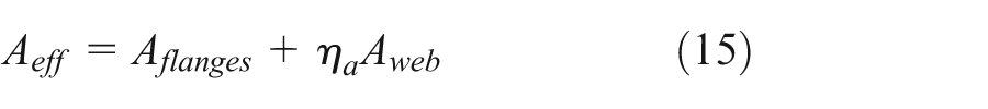
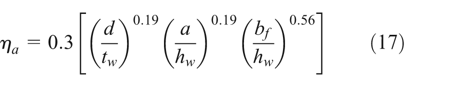
where Ig is the gross moment of inertia, Aflanges is the total sectional area of the top and bottom flanges, Aweb is the web sectional area, and ηf and ηa are the factor of effective moment of inertia and factor of effective web area, respectively, calculated as follows (Kim et al., 2011)
Abbas et al. (2006) showed that the stress of flange transverse bending moment should be considered in addition to the stress due to the in-plane bending moment.
Shear behavior
Timoshenko and Gere (1961) showed that the elastic local shear buckling strength of corrugated web τcr,L can be calculated as follows
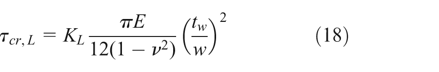
where ν is the Poisson’s ratio, w is the maximum of the longitudinal part width and the diagonal part width as shown in Figure 4, E is the modulus of elasticity, and KL is the factor of local shear buckling based on the ratio of (w/hw) and the boundary conditions that are 8.98 and 5.34 for the web fixed support and the web simple support, respectively.
Easley (1975) proposed equation (19) to estimate the elastic global shear buckling strength τcr,G (if Dy/Dx > 200)
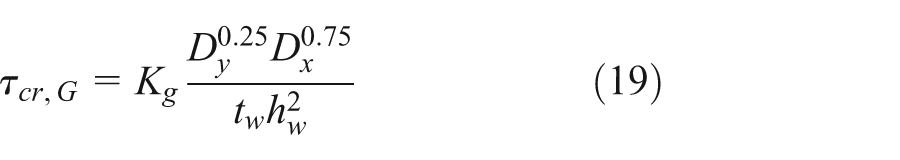
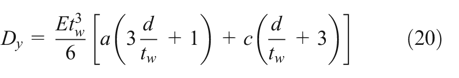
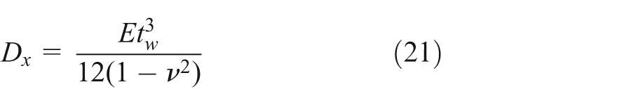
where Kg is the global shear buckling factor based on the boundary conditions which are 64.8 and 36 for the web fixed support and the web simple support, respectively, and Dy and Dx are the rigidity of the corrugated web around the strong axis and the weak axis, respectively, which are defined by equations (20) and (21) (Easley, 1975)
In the case that the elastic local and global shear buckling strengths become more than 80% of the shear yield strength τy, Elgaaly et al. (1996) proposed the inelastic shear buckling strength τcr,inelastic as follows
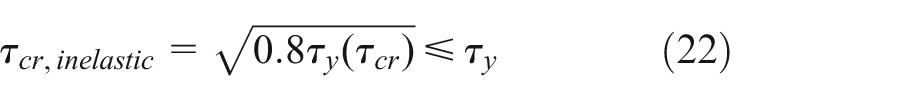
where τcr is the τcr,L for inelastic local shear buckling strength, and τcr is the τcr,G for inelastic global shear buckling strength. von Mises yield criterion is used to define the shear yield strength as follows
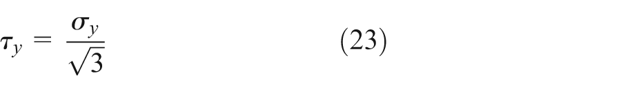
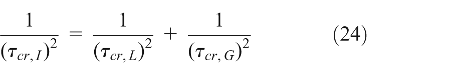
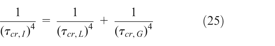
where σy is the yield strength of the steel corrugated web. In order to consider the interaction shear buckling strength of corrugated web τcr,I, Abbas et al. (2002), Shiratoni et al. (2003), and Sayed-Ahmed (2005) proposed equations (24)–(26), respectively
Nonlinear finite element models
In order to compare the behavior of the corrugated webbed beams with wide flange beams in the described PT semi-rigid connection, six specimens of the corrugated webbed beams with the same web height as W36 × 160 have been considered in finite element (FE) analysis. These specimens were simulated using well-known software ABAQUS 6.11-PR3 to show that use of beams with thinner corrugated web and greater flange area is more economical than the traditional wide flange beams in the PT connections additional to the similar load-carrying capability.
The modeling setup of the PT connection is shown in Figure 5; all connections have been simulated as an interior connection of a steel MRF. The column was a wide flange section (W14 × 398) and it was free at the top where cyclic loading has been applied. The dimension of the top and bottom angles as energy dissipators was L203 × 203 × 19 with 406 mm width. The angles were bolted to the column flanges and the beam flanges by A490 high-strength bolts with a diameter of 32 mm (1¼ in). The arrangement of the bolts were similar to that of the bolts in the PT connection studied by Garlock et al. (2005) in which four bolts connected the angle to the column flange were arranged in a row with a distance of 137 mm to the angle bottom, and four bolts connected the angle to the beam flanges were arranged in two rows. The bolts were tensioned to the minimum pretension force which was 454 kN (102 kips) according to American Institute of Steel Construction (AISC) (2010b). Post-tensioning force was applied by seven-wire ASTM A416 high-strength steel strands with the area of 140 mm2 each that were passed parallel to the beams through the drilled holes in the column flanges. The holes of 44-mm diameter were used to pass two or three strands that were similar to Garlock et al. (2005). The strands were symmetrically put around the beam centroid in order to set the centroid of strands at the beam centroid. The distance of the strands from the beam web and their distance from each other is shown in Figure 5. Furthermore, the dimensions of the corrugated web welded one-sided to the beam flanges were as follows: a = 350 mm, b = 300 mm, and d = 300 mm.
Modeling setup.
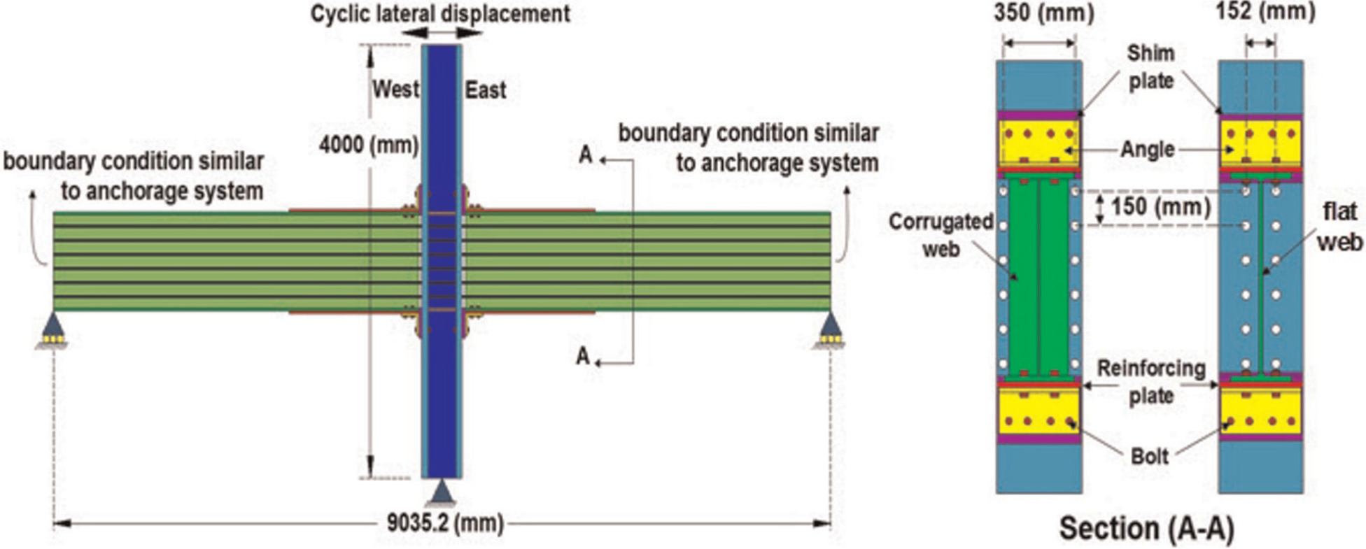
Table 1 demonstrates the dimensions of the studied beams and the characteristics of high-strength steel strands where tflange is the thickness of the beam flange, Ns is the number of the steel strands, and Tu is the ultimate force that all steel strands can carry. Specimens with the corrugated web have flange width of 350 mm and less weight per meter length compared to the specimen including W36 × 160. Reinforcing plates with 400 mm width have length Lrp and thickness trp as shown in Table 2, in which their lengths were selected to prevent beam flange strain to exceed two times of yield strain. Also, thickness of doubler plates tdoubler, height of shim plates hshim, and thickness of shim plates tshim are shown in Table 2 (shim plates with 400 mm width were used to prevent contact between the beam web and the column flange); in addition, AISC (2010b) was used to design the dimensions of doubler plates and continuity plates mentioned in this table (continuity plates had the same thickness as the beam flanges).
Dimensions of beam specimens and characteristics of steel strands.
Dimensions of reinforcing, doubler, and shim plates.
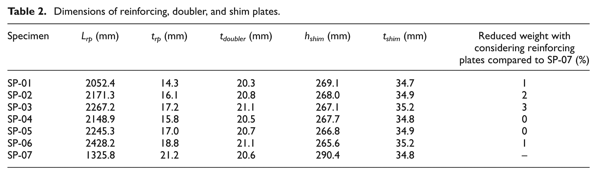
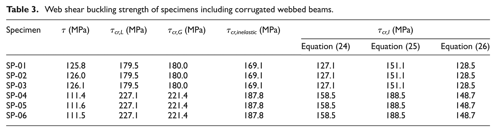
Table 3 shows web shear buckling strength of the specimens including the corrugated webbed beams in which critical buckling strengths were estimated by interaction buckling strength; also, according to AISC (2010b), nominal shear strength of W63 × 160 beam in SP-07 is 3125 kN, and shear force is 867 kN. In all beam specimens, no web buckling is occurred based on the theoretical predictions.
Web shear buckling strength of specimens including corrugated webbed beams.
Material properties
The inelastic behavior of the materials was considered to develop FE models. Due to the fact that the results of material coupons and bolt tests were unavailable, reasonable stress–strain relationships for three steel material types were defined to incorporate the inelastic behavior and strain-hardening of steel materials as shown in Table 4.
Material properties.
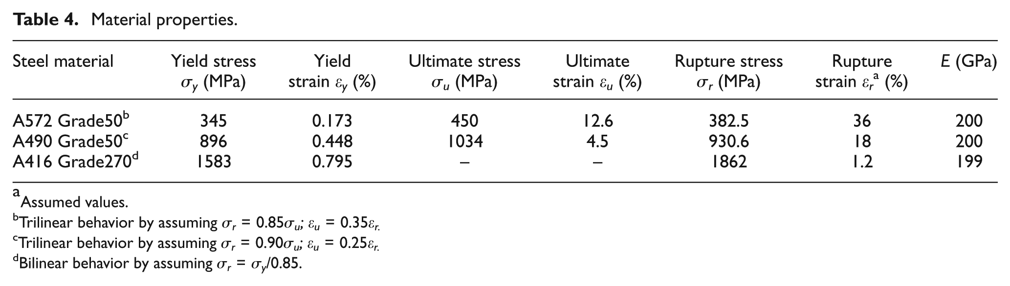
Assumed values.
Trilinear behavior by assuming σr = 0.85σu; ϵu = 0.35ϵr.
Trilinear behavior by assuming σr = 0.90σu; ϵu = 0.25ϵr.
Bilinear behavior by assuming σr = σy/0.85.
In this table, A490 Grade50 was assigned to the high-strength bolts (American Society for Testing and Materials (ASTM), 2015c), A416 Grade270 was assigned to the steel strands (ASTM, 2015b), and A572 Grade50 was assigned to the rest steel components (ASTM, 2015a).
Contact conditions
In ABAQUS 6.11-PR3, the contact type was defined as surface-to-surface contact. Since in bolting there is expected to be little relative sliding of one surface along the other, small sliding in the sliding formulation was used. Two contact directional properties, normal and tangential, were defined for this class of problems in ABAQUS. Normal contact specified as a hard-contact is behavior perpendicular to the surface, whereas tangential contact specified by penalty method with friction coefficient of 0.35 in the modeling is transverse to the surface (ABAQUS 6.11-PR3, 2011; AISC, 2010b).
The contacts defined in the FE modeling between the steel components were as follows: (1) contact between the column bolt nut and the column leg of the angle, (2) contact between the column leg of the angle and the shim plate, (3) contact between the reinforcing plate and the shim plate, (4) contact between the beam flange and the shim plate (in SP-07: contact between W36 × 160 and the shim plate), (5) contact between the column flange and the column bolt head, (6) contact between the column bolt shank and the bolt hole of the column leg of the angle, (7) contact between the column bolt shank and the bolt hole of the shim plate, (8) contact between the column bolt shank and the bolt hole of the column flange, (9) contact between the beam bolt head and the beam leg of the angle, (10) contact between the beam leg of angle and the reinforcing plate, (11) contact between the beam flange and the beam bolt nut (in SP-07: contact between W36 × 160 and the beam bolt nut), (12) contact between the beam bolt shank and the bolt hole of the beam leg of the angle, (13) contact between the beam bolt shank and the bolt hole of the reinforcing plate, and (14) contact between the beam bolt shank and the bolt hole of beam flange (in SP-07: contact between the beam bolt shank and the bolt hole of W36 × 160).
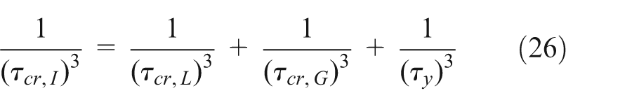
Boundary conditions
The hinged support at the column base and the roller supports at the end of beams were simulated by proper boundary conditions in ABAQUS 6.11-PR3; furthermore, appropriate boundary conditions were applied at the end of the beams to simulate the effect of the anchorage system anchoring the steel strands. In order to prevent the out-of-plane displacements, the corrugated webbed beams were laterally braced according to the investigation by Yu and Sause (2006), and W36 × 160 beams were laterally braced in accordance with AISC (2010a) seismic provisions; in addition, all beam specimens were laterally braced at the end of beams. In all specimens, high-strength bolts were tensioned to the minimum bolt pretension; it was applied as a boundary condition simulated in ABAQUS by splitting the bolt body in the middle, perpendicular to the bolt shank, and pulling each end toward the other to obtain the desired pretension force. Since fillet welds were used to connect shim plates to column flanges, the shim plates were constrained to the column flanges using the type of tie constraint simulating the welds according to ABAQUS 6.11-PR3 (2011). Similarly, this type of constraints were applied as the boundary conditions in order to model the welds connecting the reinforcing plates to the beam flanges, one-sided welds connecting the beam flanges to the corrugated web, and the welds of the doubler plates and the continuity plates.
Loading system
The specimens were subjected to cyclic loading applied at the top of the column in accordance with the requirements in AISC (2010a) as follows: 0.375%, 0.50%, and 0.75% drifts with six cycles each, 1% drift with four cycles, 1.5%, 2%, 3%, and 4% drifts with two cycles each; in addition, the initial post-tensioning force was applied using the steel strands.
Element types
All components except the strands were modeled using three-dimensional (3D) solid shape with C3D8R solid elements which are eight-node elements and the strands were modeled using 3D wire shape with B31 beam elements which are two-node elements from various element types defined in ABAQUS 6.11-PR3 (2011). Figure 6 shows the frame of SP-03 meshed by the above-mentioned elements.
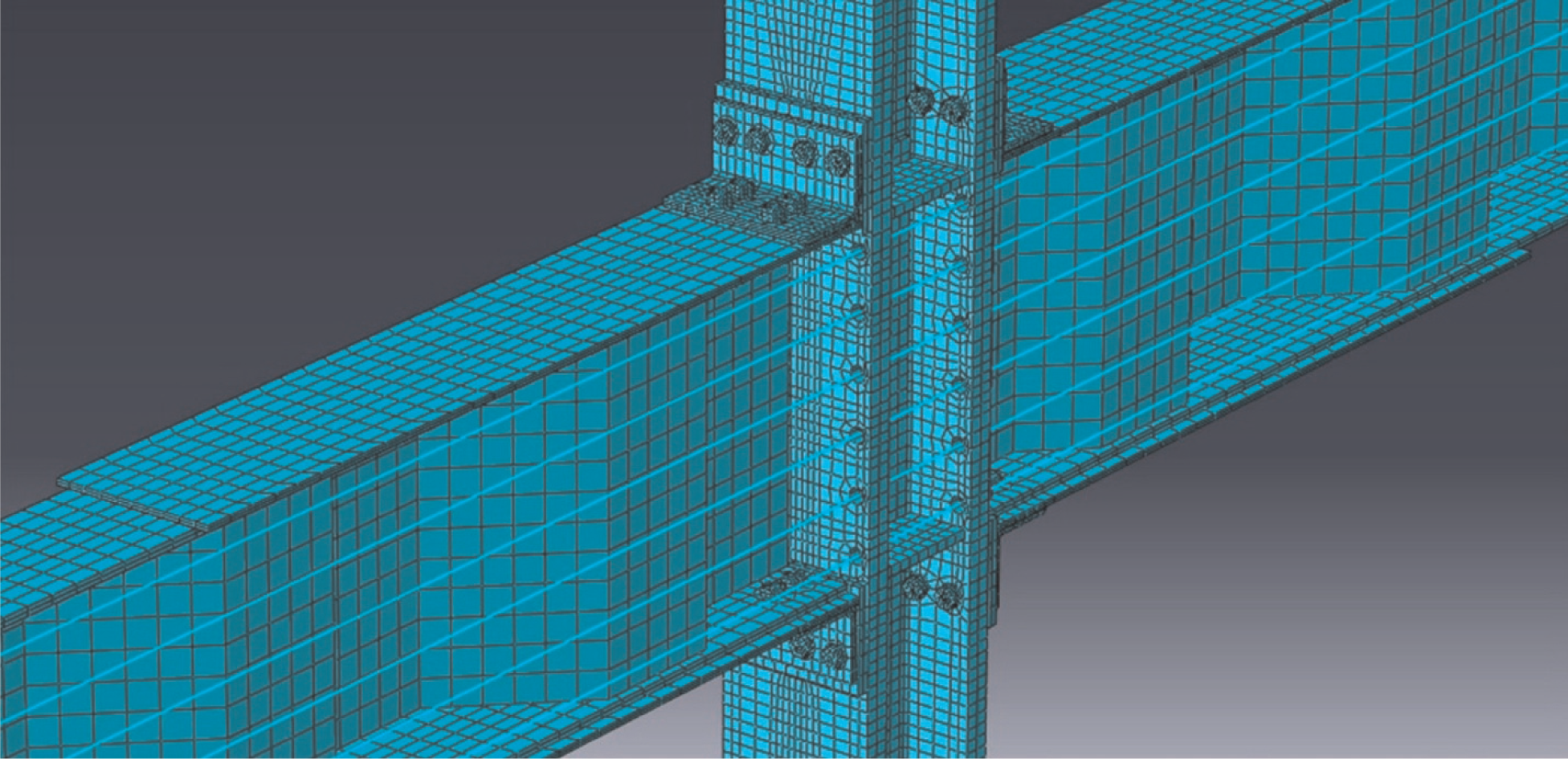
Meshed frame of SP-03.
Mesh quality
In order to assess the quality of meshing used in simulating the specimens under cyclic loading, key mesh metrics (aspect ratio, skewness index, and orthogonality ratio) for the steel components are included in Table 5. The worst and average values of the above-mentioned factors have been included in the table to provide full understanding of the meshing quality of the steel components. As is mentioned in Table 5, the worst aspect ratio among the elements of the steel parts meshing was restricted to 4.523 that was found in meshing the corrugated webs, the worst skewness index was 0.518 belonging to an element of W14 × 398 meshing, and the worst orthogonality ratio was limited to 0.646 which was in meshing the beam bolts.
Key mesh metrics of steel components.
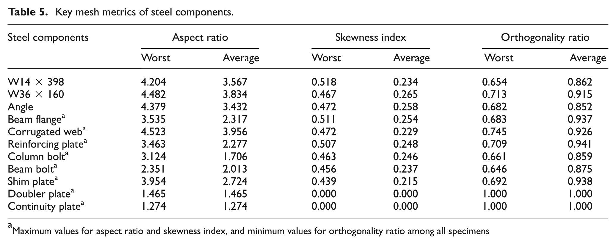
Maximum values for aspect ratio and skewness index, and minimum values for orthogonality ratio among all specimens
Results of FE analysis
The steel components of the studied specimens except the angles of the PT semi-rigid connections remained elastic under lateral cyclic loading up to 4% (column tip displacement of 160 mm), so the inelastic deformations of the bolted angles provided reliable energy dissipation with no fracture. Furthermore, beam specimens did not suffer from beam flange buckling and web shear buckling according to the results of the buckling analysis; this point in the corrugated webbed beams is due to high resistance of the corrugated panel against shear buckling which leads to the proper function of I-section beams with thin corrugated web and thick flanges in the PT connections.
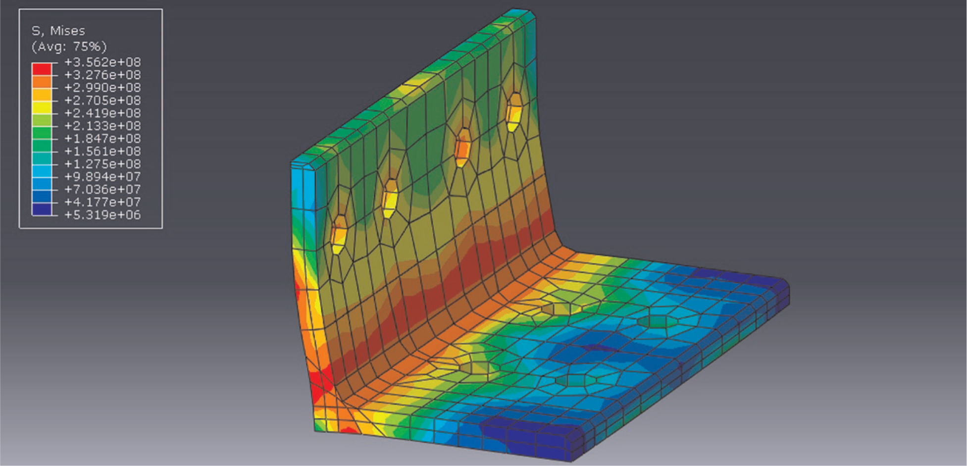
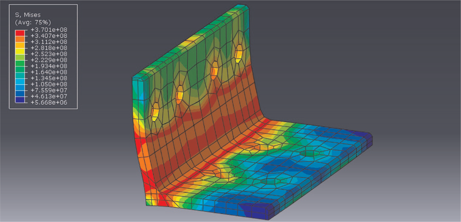
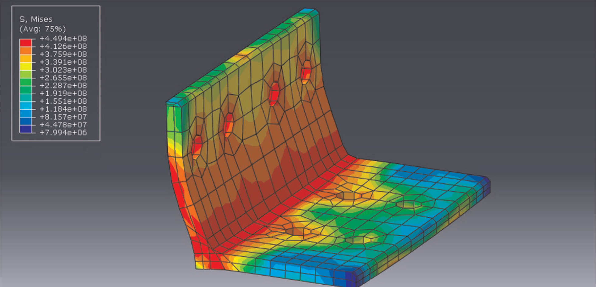
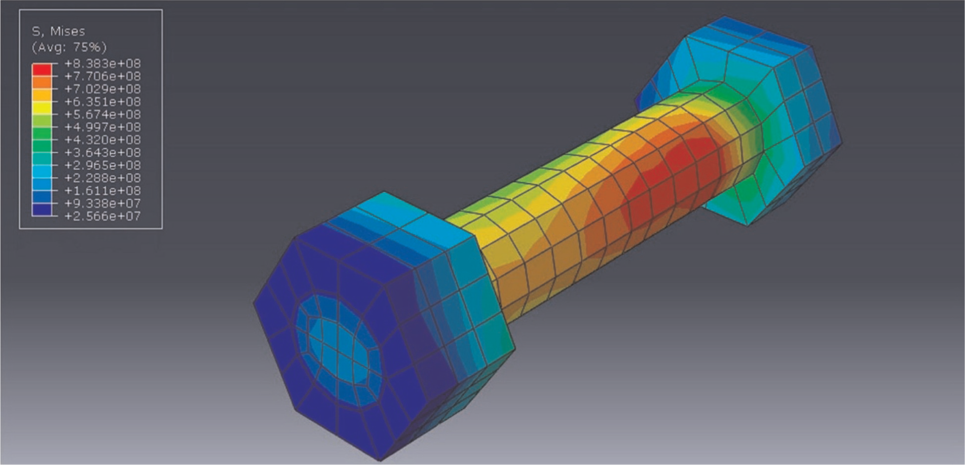
Furthermore, using the corrugated webbed beams instead of I-section traditional beams in the PT semi-rigid connections results in less weight of steel MRFs in addition to the same bending strength. Figures 7 to 9 show the stress contour based on the von Mises criterion in the deformed shape of SP-01, SP-06, and SP-07 at 4% drift, respectively. The gap opening at the beam–column interface after decompression led to energy dissipation provided by the inelastic deformations of the angles.
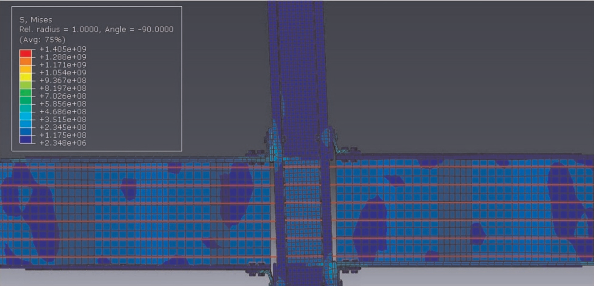
Stress contour in deformed shape of SP-01 at 4% drift.
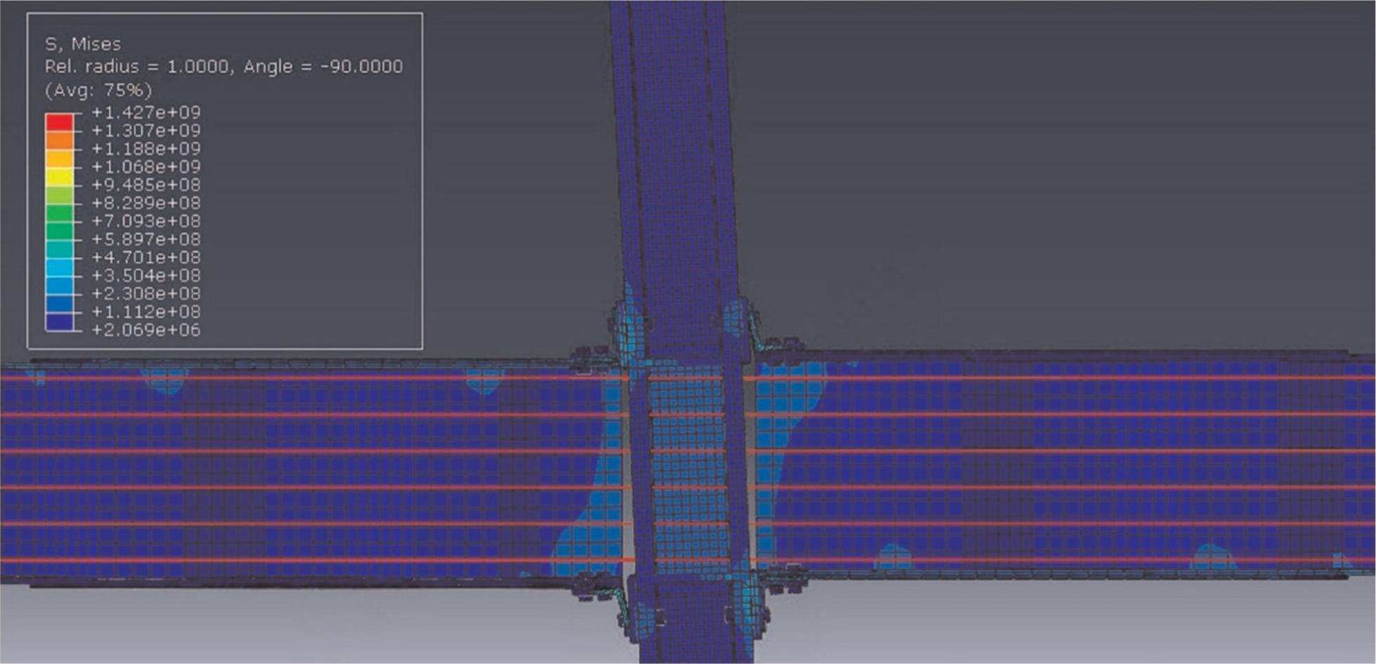
Stress contour in deformed shape of SP-06 at 4% drift.
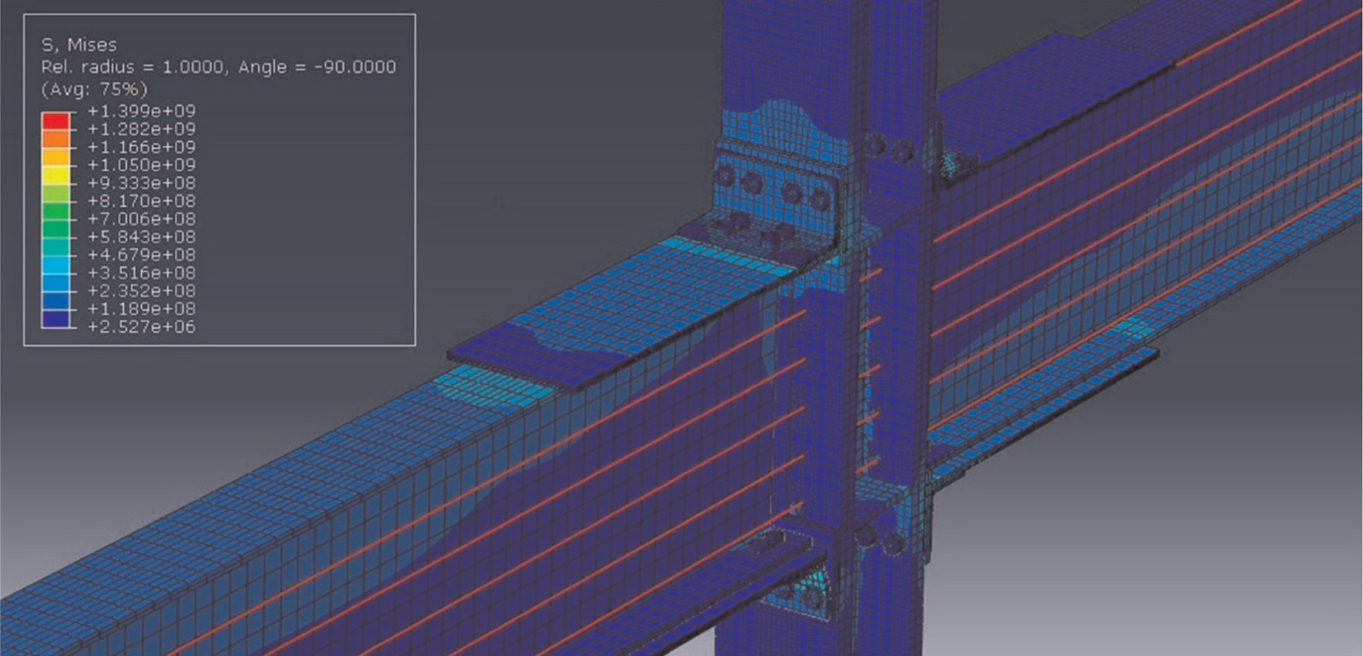
Stress contour in deformed shape of SP-07 at 4% drift.
Figure 10 shows the angle stress contour of SP-02 at the first 1.15% drift; as is obvious, the first plastic hinge formed near the fillet of the column leg of the angle. Mesh metrics of the angle were as follows: aspect ratio (worst: 4.387; average: 3.436), skewness index (worst: 0.476; average: 0.260), and orthogonality ratio (worst: 0.675; average: 0.849).
Angle stress contour of SP-02 at 1.15% drift.
Figure 11 shows the angle stress contour of SP-02 at the first 1.4% drift; the other two plastic hinges contributing to the yield mechanism formed on the fillet of the beam leg of the angle and near the column bolts. Mesh metrics of the angle were as follows: aspect ratio (worst: 4.398; average: 3.442), skewness index (worst: 0.489; average: 0.266), and orthogonality ratio (worst: 0.664; average: 0.841).
Angle stress contour of SP-02 at 1.4% drift.
Figure 12 shows the angle stress contour of SP-02 at 4% drift; mesh metrics of the angle were as follows: aspect ratio (worst: 4.484; average: 3.476), skewness index (worst: 0.514; average: 0.283), and orthogonality ratio (worst: 0.647; average: 0.826).
Angle stress contour of SP-02 at 4% drift.
Figure 13 shows the equivalent plastic strain (PEEQ) contour of the angle of SP-02 at 4% drift. As is demonstrated in the figure, the fillet of the angle has undergone considerable amount of PEEQ.
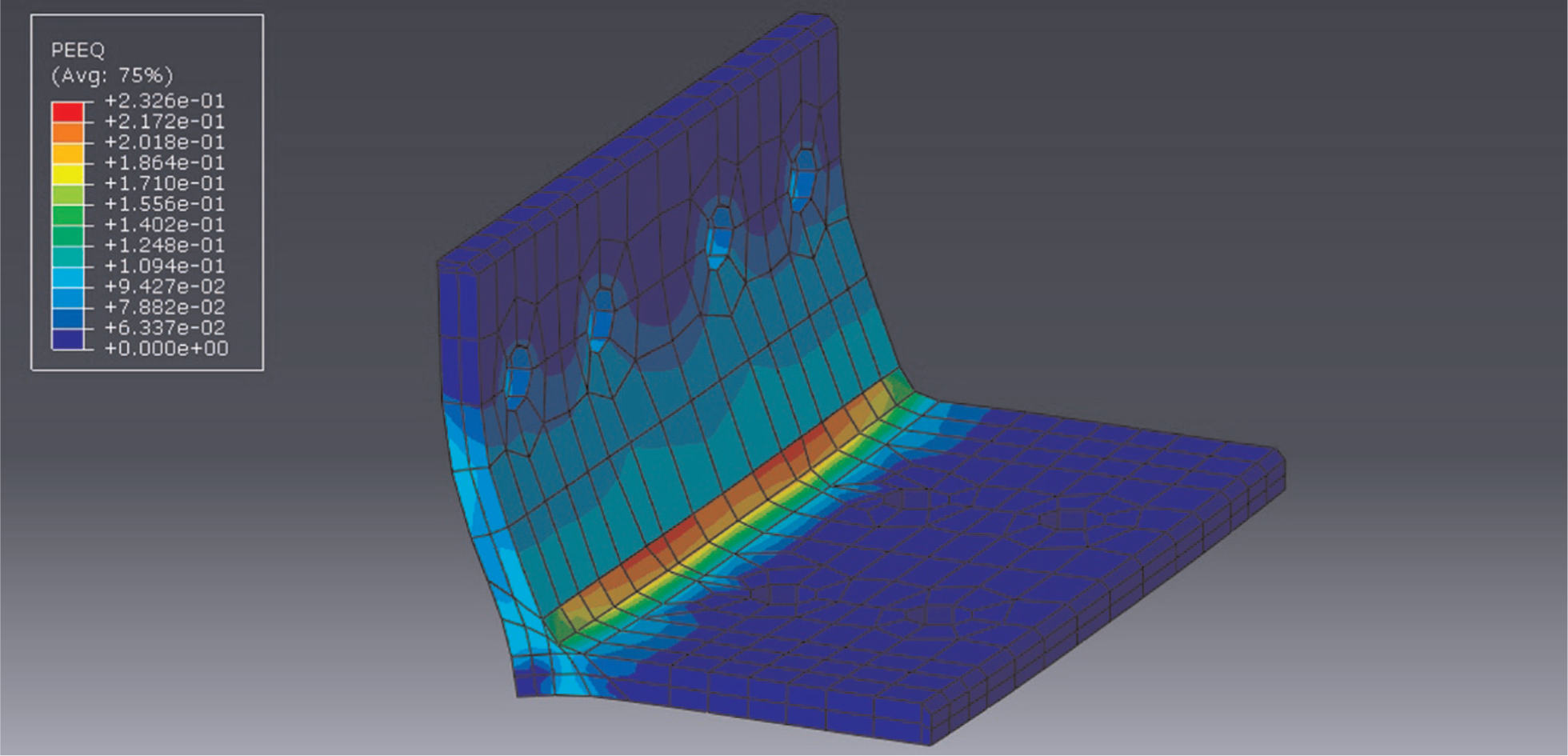
Angle PEEQ contour of SP-02 at 4% drift.
In addition, the connection bolts of the specimens did not yield. Figure 14 shows the column bolt stress contour of SP-05 at 4% drift and mesh metrics of the bolt were as follows: aspect ratio (worst: 3.186; average: 1.727), skewness index (worst: 0.487; average: 0.258), and orthogonality ratio (worst: 0.645; average: 0.846).
Column bolt stress contour of SP-05 at 4% drift.
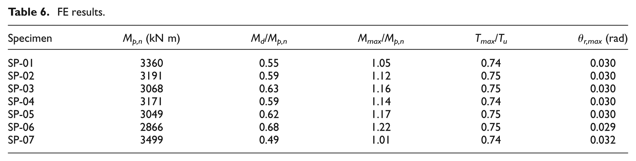
Table 6 shows the FE results of the specimens. The table includes the decompression moment Md, maximum moment Mmax, maximum post-tensioning force Tmax, and maximum relative rotation at the beam–column interface θr,max obtained from simulating by ABAQUS 6.11-PR3.
FE results.
All specimens returned to their initial position without strand yielding at the end of 4% drift which shows the sufficient number of the steel strands in different specimens. Figure 15 shows the comparative plot of the envelope of the post-tensioning force of the strands versus relative rotation obtained from the theoretical response (equation (3)) and the FE results for SP-03.
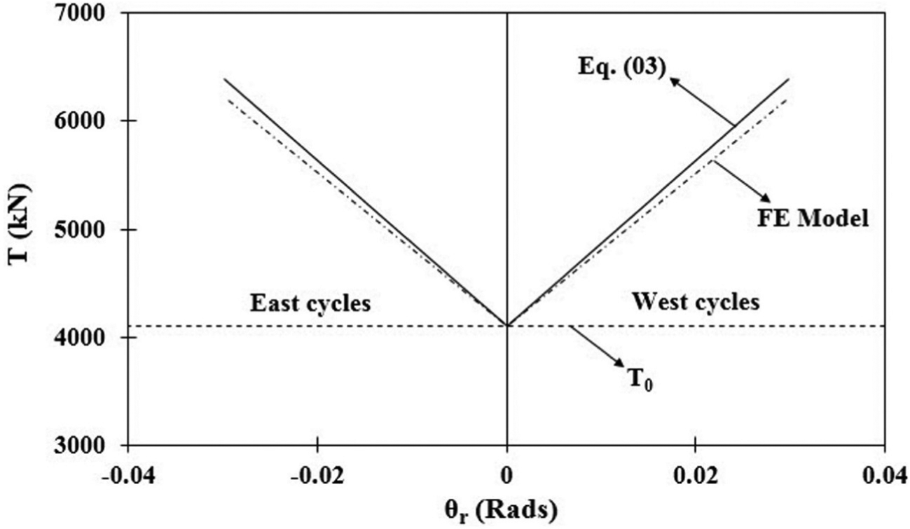
Post-tensioning force–relative rotation response of SP-03.
Figure 16 demonstrates the moment normalized by Mp,n versus relative rotation at the beam-column interface of the specimens with the corrugated web thickness of 8 mm (SP-01, SP-02, SP-03) and SP-07 as comparison. Figure 17 represents the normalized moment–relative rotation response of the specimens with the corrugated web thickness of 9 mm (SP-04, SP-05, SP-06) and SP-07 as comparison. Figure 18 shows lateral load Plateral versus displacement of column tip Δ of SP-01 compared to SP-07.
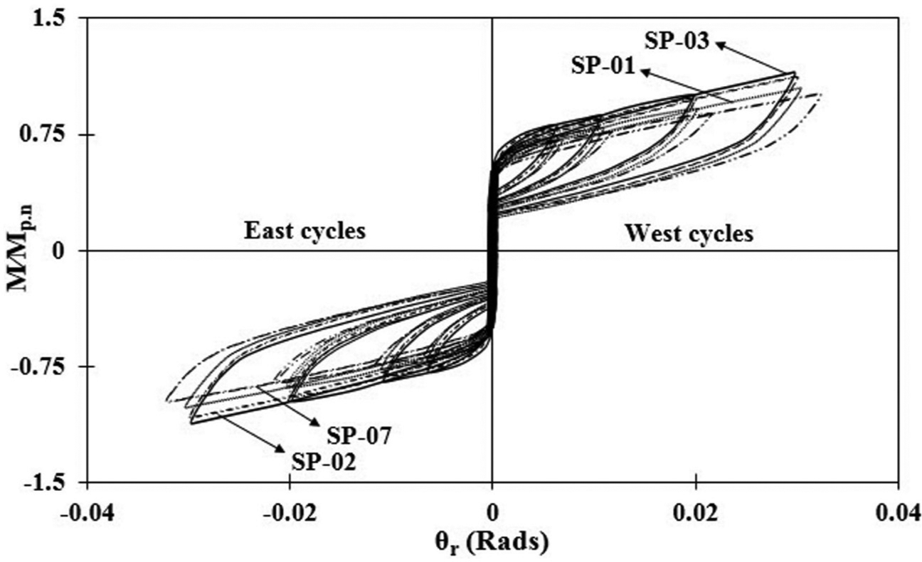
Normalized moment–relative rotation response of SP-01, SP-02, SP-03, and SP-07.
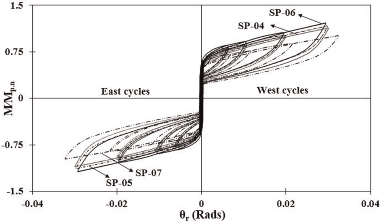
Normalized moment–relative rotation response of SP-04, SP-05, SP-06, and SP-07.
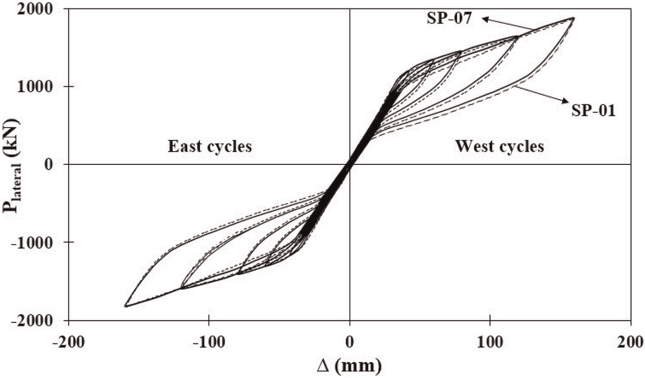
Lateral load–displacement response of SP-01 and SP-07.
Comparison between FE results and theoretical responses
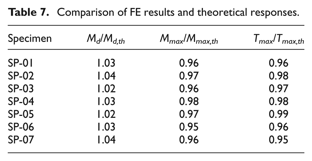
Comparison between the results of the FE analysis using ABAQUS 6.11-PR3 and the theoretical responses for different specimens in the PT semi-rigid beam-to-column connection subjected to cyclic loading up to 4% story drift are given in Table 7. According to this comparison, the behavior of the corrugated webbed beams in the PT connections is accurately predicted by the described theoretical analysis.
Comparison of FE results and theoretical responses.
Conclusion
A theoretical analysis proved by an FE analysis simulated by well-known software ABAQUS 6.11-PR3 has been presented to study the behavior of the corrugated webbed beams in PT steel semi-rigid connections subjected to severe cyclic loading. Six specimens with the corrugated webbed beams have been studied that result in less weight and lower fabrication costs in comparison with a traditional wide flange beam. The bolted top and bottom angles are essential parts providing reliable level of energy dissipation while high-strength steel strands provide self-centering capability for the PT connection and enable the MRF to revert to its initial position without any residual drift after an earthquake. In order to reach an accurate design, the contribution of the corrugated web in the flexural and axial rigidities of the beam has been considered and the results of the FE modeling show that the simple theoretical analysis accurately predicts the shear and flexural behavior of the corrugated webbed beams in PT semi-rigid connections. Also, the FE results demonstrate stable hysteretic behavior of the PT connections without beam web shear buckling, beam flange buckling, and strand yielding.
Footnotes
Declaration of Conflicting Interests
The author(s) declared no potential conflicts of interest with respect to the research, authorship, and/or publication of this article.
Funding
The author(s) received no financial support for the research, authorship, and/or publication of this article.