
Abstract
A damage identification approach is presented using substructure virtual distortion method which takes the advantage of the fast structural reanalysis technique of virtual distortion method. The formulas of substructure virtual distortion method are deduced in frequency domain, and then the frequency response function of the damaged structure is constructed quickly via the superposition of the frequency response function of the intact structure and the frequency responses caused by the damage-coupling virtual distortions of the substructures. The structural damage extents are identified using the measured modal parameters. Two steps are adopted to increase the efficiency of optimization: the modals of finite element model are estimated quickly from the fast constructed frequency response function during the optimization and the primary distortions of the substructures are extracted by contribution analysis to further reduce the computational work. A six-story frame numerical model and an experiment of a cantilever beam are carried out, respectively, to verify the efficiency and accuracy of the proposed method.
Keywords
Introduction
In recent decades, structural health monitoring (SHM) has been one hot research topic in civil engineering which provides invaluable evidence on structural safety evaluation and integrity maintenance (Farrar and Worden, 2007; Yi et al., 2013a; Zhou et al., 2013a). Damage identification plays an important role in SHM. At present, many effective methods of damage identification have been investigated and presented (Sohn et al., 2001; Yi et al., 2011). However, in practice, there are still many difficulties on accurate identification of large and complex structures in civil engineering due to the limited measurements, insensitivity of local damages, complex boundary condition, and so forth.
One kind of preferable approaches for damage identification is based on the structural vibrations, which this article considers. Appearance of damages is easy to bring the changes in the structural responses or its dynamic characteristics. Generally, structural damages are identified by comparing the differences between the intact structure and damaged structure. The existing identification methods based on vibrations (Fan and Qiao, 2011; Yi et al., 2013a) are usually studied in three domains which are frequency domain, time domain, and modal domain. The structural modal parameters, such as natural frequencies and modal shapes, are easy to be obtained, especially thanks to the rapid development of experimental modal analysis technique, and hence, they are popularly used for damage identification. Wang et al. (2000) use modal sensitivity analysis for damage identification of the finite element (FE) mode of Tsing Ma Bridge in Hong Kong. Zhou et al. (2013b) use the response surface method of structural natural frequencies for model updating of large and complicated structures such as long-span cable-stayed bridges. Doebling et al. (1996) give a summary review of modal methods, which detect, locate, and identify damages by the changes in the related modal parameters; the extensive reviews can be found in Carden and Fanning (2004) and Fan and Qiao (2011).
Structural damage identification usually requires the reanalysis of structural FE model and the repeated assembling of structural system matrices during the optimization. This is time-consuming or even is impractical for large-scale structure in civil engineering. To achieve effective identification of large structures, many researches have been investigated including substructuring method, virtual distortion method (VDM), and so on.
The substructuring method is promising in both the forward analysis and inverse analysis for large-scale structure monitoring. For forward analysis, the substructures are analyzed individually to obtain their designated solutions, which are then assembled to recover the global structural properties (Craig, 2000). Weng et al. (2011) proposed an iterative substructuring method to obtain accurately the eigensolutions and eigensensitivities of the structures, which can be used to recover the eigensolutions and eigensensitivities of original global structure efficiently. Xia et al. (2010) developed the Kron’s substructuring method to compute the first-order derivatives of the eigenvalues and eigenvectors with respect to the structural parameters, and the method is proved efficiently and accurately by a highway bridge. Besides the forward approaches, substructuring methods have also been widely researched in the inverse problems of local damage identification or model updating, which can reduce requisite sensors and improve identification accuracy and efficiency. Generally, the inverse problems aim at separating the substructure from global structure, and the identification is implemented mostly based on the equation of motion of the substructure. The interface forces on the substructure boundary which couple with the influences of the rest of the structure are often unknown and need to be identified together with unknown substructure parameters. Law et al. (2010) identified the coupling forces between the substructures under support excitation and the local structural damage is then detected from the identified coupling forces based on dynamic sensitivity analysis. Zhu et al. (2013) derived the dynamic response sensitivities with respect to the structural parameters and the related forces, and then the structural damages, external moving forces, and interface forces are identified simultaneously. Hou et al. (2012, 2015) proposed and developed an isolated substructure method, and the substructure is isolated from the global structure numerically into a simple independent structure which is used for substructure identification.
VDM belongs to fast structural reanalysis methods (Akgün et al., 2001) and is applied in both structural statics and dynamics (Holnicki-Szulc, 2008; Kołakowski et al., 2008). It introduces virtual distortions to simulate structural damages or parameter modifications (mass, damping and stiffness), and when the intact structural responses are known, the responses of the modified structure can be computed quickly without reanalysis of the whole structure. Based on VDM, Zhang et al. (2010a, 2010b) proposed a method for simultaneous identification of unknown loads and structural damages. In Zhang et al. (2010a), both the damage extents and damage types (breath crack for example) can be determined by recovering the strain–stress relationships of the damaged elements. In Zhang et al. (2010b), damages and multiple moving masses are identified by parameterizations of the unknown moving loads. Swiercz et al. (2008) formulated VDM in frequency domain for damage identification with the assumption of using harmonic excitations which is a quasi-static problem.
This article extends VDM into frequency domain by performing Fourier transform on basic equations of VDM in time domain. Section “SVDM” discusses the equations of substructure virtual distortion method (SVDM) which built the relations among substructure virtual distortions, substructure damage extents, and the structural responses in time domain. Section “Frequency-domain fast structural reanalysis based on SVDM” deduces the fast structural reanalysis based on SVDM in frequency domain, where frequency response function (FRF) of the damaged structure is constructed via the superposition of the corresponding function of the intact structure and the frequency response caused by the virtual distortions corresponding to the primary distortions. Section “Damage identification” discusses inverse problem of damage identification. Sections “Numerical example” and “Experimental test” verify the proposed approach, respectively, using a numerical frame and an experiment of a cantilever beam. Conclusion is in section “Conclusion.”
SVDM
Substructure virtual forces
The basic relations among substructure damage, virtual distortions, and the response of the damaged structure can be deduced in terms of the FE model. Let
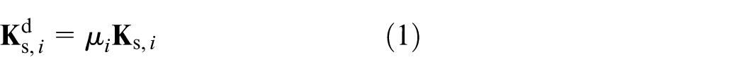
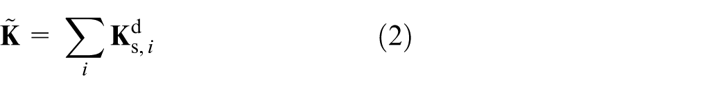
The stiffness matrix of the global damaged structure
Denote the mass matrix and damping matrix of the damaged structure as

where vector
Substitute equations (1) and (2) into equation (3) and move the modified parts of the stiffness matrix to the right-hand of the equation, there is

where vector
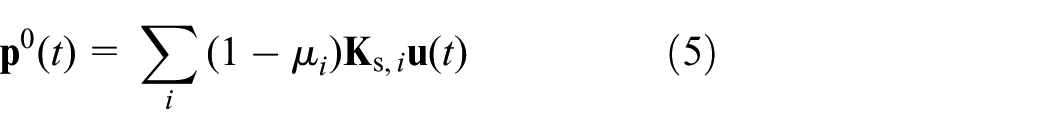
Equations (4) and (5) imply that the responses of the damaged structure can be modeled equally by linear combination of the intact structural responses to the same excitation
Let

where
Substitute equation (6) into equation (5), the formula can be rewritten as
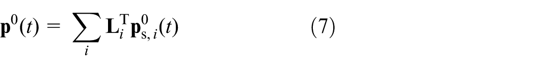
where

Define

where vector

Substructure virtual distortion and damage extent
Similar to virtual distortions defined in VDM (Zhang et al., 2010b), distortions caused by virtual force
Let
Since
where
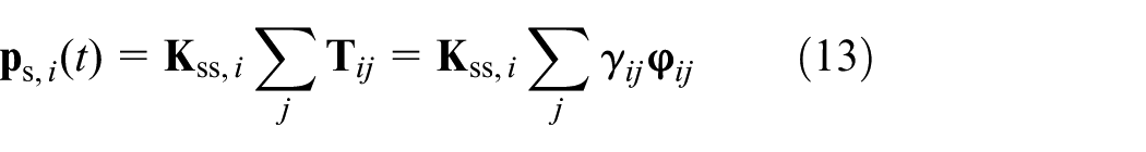
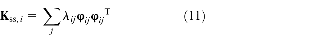
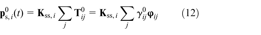
where
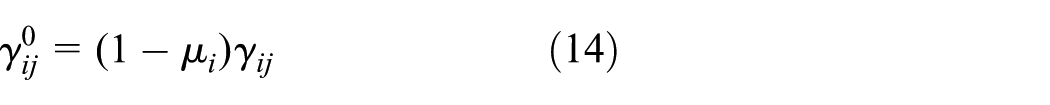
Substitute equations (12) and (13) into equation (10), the relation among the damage extent, substructure virtual distortion, and its actual distortion can be deduced as equation (14) in terms of their coefficients
Structural responses
Assuming structure with zero initial condition, via equation (4), the responses of the damaged structure at the αth sensor (linear sensor)
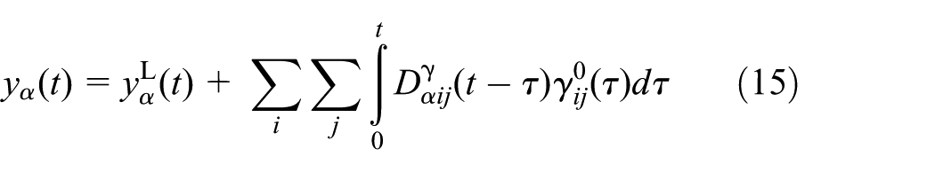
where
In equation (15), responses
In order to compute the coefficient
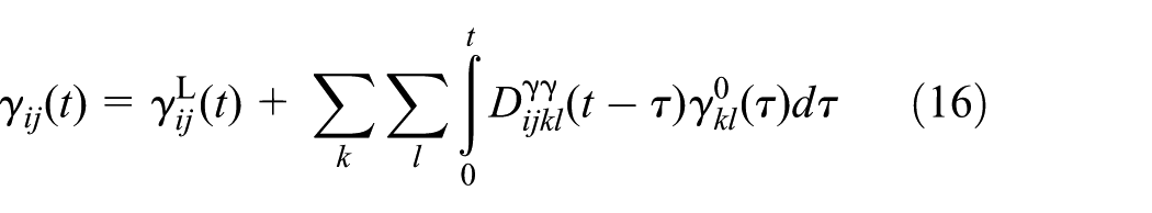
where
By combining equations (14) and (16), there is
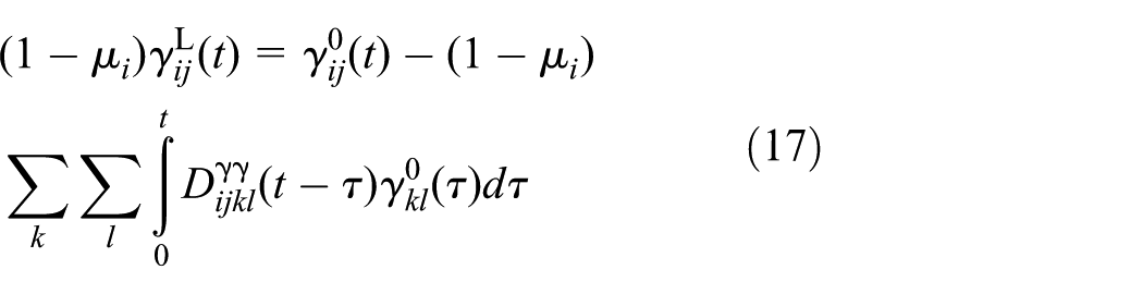
Collecting all the responses
Frequency-domain fast structural reanalysis based on SVDM
Fourier transform of structural responses
In equation (15), structural dynamic response
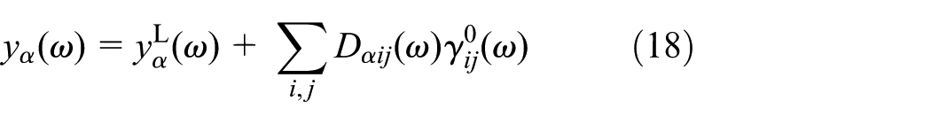
where
Equation (18) shows that the responses of the damaged structure
In order to determine
Then it is easy to compute
Given damage extents
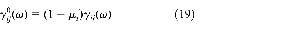
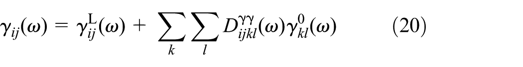
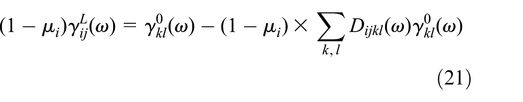
Structural FRF
If the excitation applied on the structure is unit impulse, then the caused responses in time domain are structural impulse responses and in frequency domain are FRF. In this way, similar to equation (18), the FRF of the damaged structure at the αth measurement
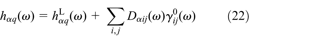
where
Primary distortion vectors
The number of substructure virtual distortions which are used to simulate damages is equal to the number of positive eigenvalues of the local substructure matrix. When the substructures are complex with lots of DOFs, the quantity of virtual distortions is certain to be huge which results in large computational work on solving the distortions. However, in practice, under certain type of excitation, some kind of distortion has little influence on structural responses which is defined as secondary distortion. The secondary distortion can be neglected during the structural analysis. On the contrary, distortion which cannot be ignored is defined as primary distortion. Therefore, during damage identification, the computational work can be reduced by only using primary distortions while ignoring the secondary distortions.
In order to extract primary distortions, contribution analysis is implemented on each substructure distortion. Denote contribution coefficient
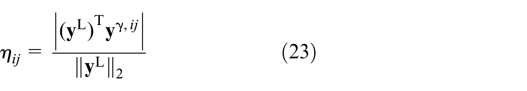
where vector
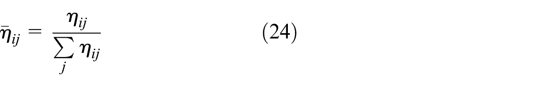
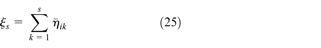
Then all the contribution coefficients of each substructure are normalized as shown in equation (24) and are ranked in a decreasing order with regard to their values, that is,
Damage identification
Given substructure damage extents, the FRF of the damaged structure can be constructed quickly through the above analysis based on SVDM. Then it is easy to obtain the structural modal parameters, such as natural frequencies and mode shapes, from the constructed FRF, which benefits the application of classical methods in modal domain for damage identification. Here, the objective function is built as
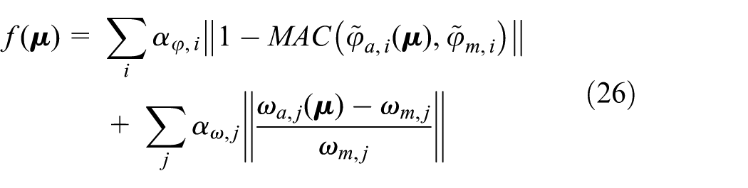
where
During damage optimization, structural modes are required to be computed repeatedly which is usually time-consuming by reanalyzing the whole structure, while here they can be obtained quickly thanks to the fast estimation of the FRF of the damaged structure. In detail, theoretical structural frequencies
Numerical example
Frame model
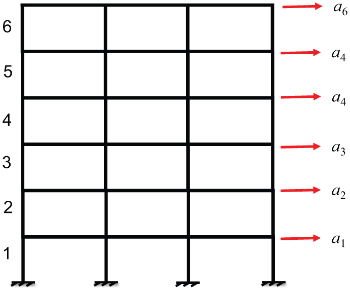
A numerical model of a six-story frame structure is used to verify the proposed method, see Figure 1. It is made of steel with Young’s modulus of 2.1 × 10¹¹ N/m2 and a density of 7.85 × 10³ kg/m3. The frame has three spans with each span of 4 m width. The height is 15 m with each story of 3 m height. The cross section of each beam and column, respectively, is 0.01 m2 with the second moment of area being 8.3 × 10⁻⁵ m4.
Numerical example of a frame structure
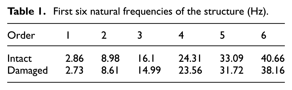
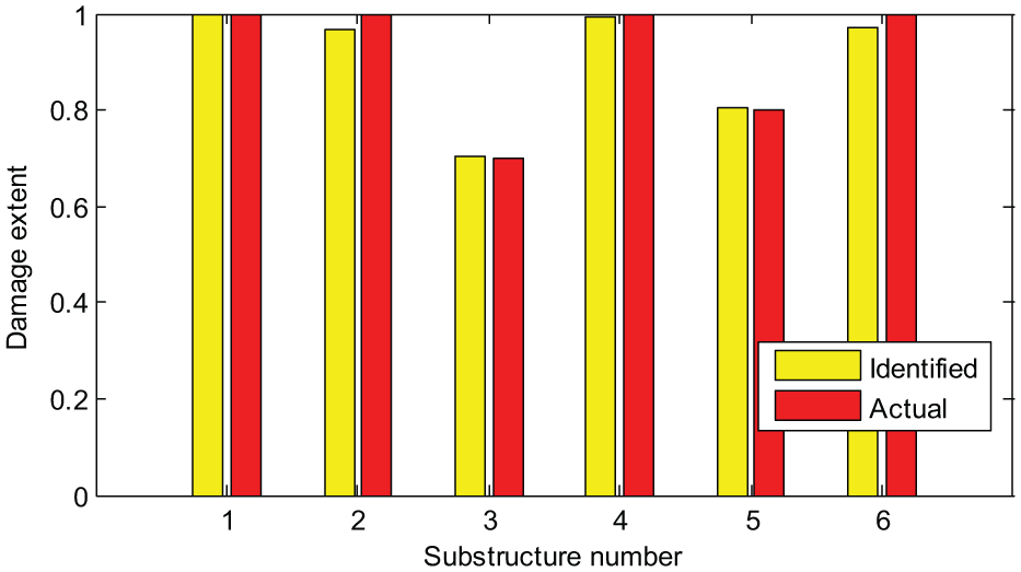
Each story which includes four columns and three beams is taken as one substructure. There are six substructures marked by 1–6 as shown in Figure 1. Substructure 3 and 5 are assumed to be damaged, respectively, with damage extents of 0.7 and 0.8, while all the rest are intact, that is, with damage extents of 1. Figure 2 shows the substructure damage extents. The first six natural frequencies of the intact and damaged structures are listed in Table 1 which are computed using the FE model. Figure 3 shows the first three mode shapes of the intact structure.
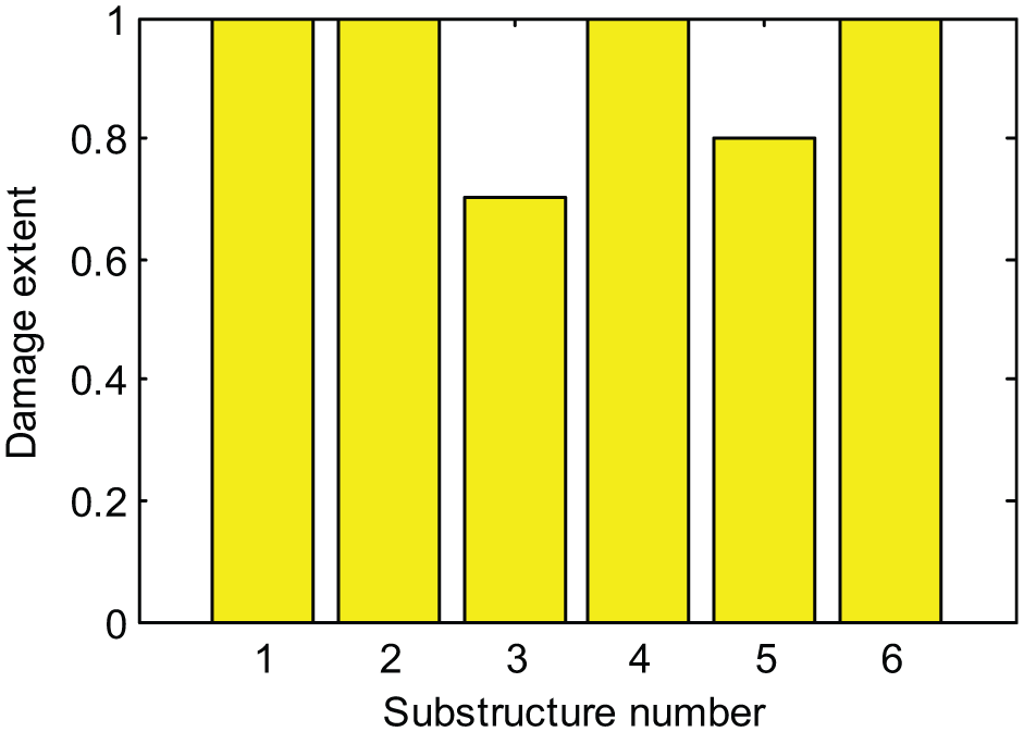
Actual damage extents of the six substructures.
First six natural frequencies of the structure (Hz).
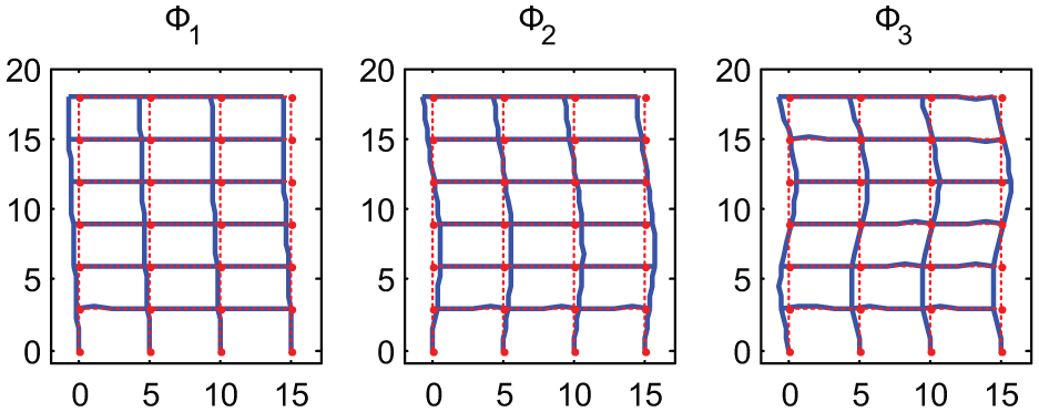
First three mode shapes of the intact structure.
Structural responses
One accelerometer is located on each story, see Figure 1, to measure structural free responses. The responses are computed using the Newmark integration method with the integration step of 0. 5 ms, and the sampling frequency is 2000 Hz. A total of 1600 time steps are used, which corresponds to the sampling time of 0.8 s. The simulated sensor responses of the damaged structure are shown in Figure 4, which contain a numerically generated uncorrelated Gaussian noise at 5% root mean square (rms) level to simulate the noise contamination in practice.
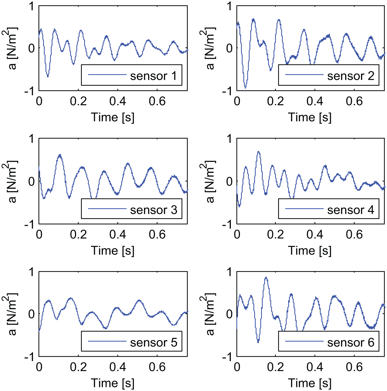
Simulated responses of damaged structure containing Gaussian noise at 5% rms level.
Extraction of primary distortions
In the procedure of damage identification, primary distortions of each substructure are analyzed and extracted first. Using FE theory, stiffness matrix of each substructure is assembled and eigenvalue decomposition is performed on them independently. The positive eigenvalues of the six substructures, respectively, are [12 21 21 21 21 21], which are also the number of the virtual distortions of each substructure. So there are 117 substructure virtual distortions required to be solved repeatedly during damage optimization. The primary distortions are extracted then to reduce the computation work. For concise, only substructure 2 is taken as an example to introduce the concrete performance.
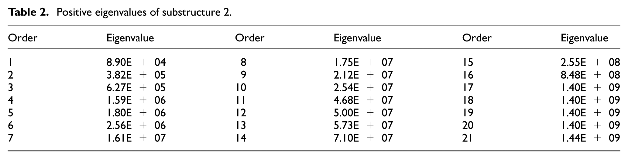
Table 2 lists 21 positive eigenvalues of substructure 2, and the corresponding 21 eigenvectors are shown in Figure 5. The sum of the first six mode shapes is used to construct the excitation which is applied on the intact structure for computing the actual distortion vectors of substructure 2. Then the computed 21 actual distortions are independently applied on the intact structure as excitations, and thus, respectively, caused 21 groups of structural responses at sensor position, that is,
Positive eigenvalues of substructure 2.
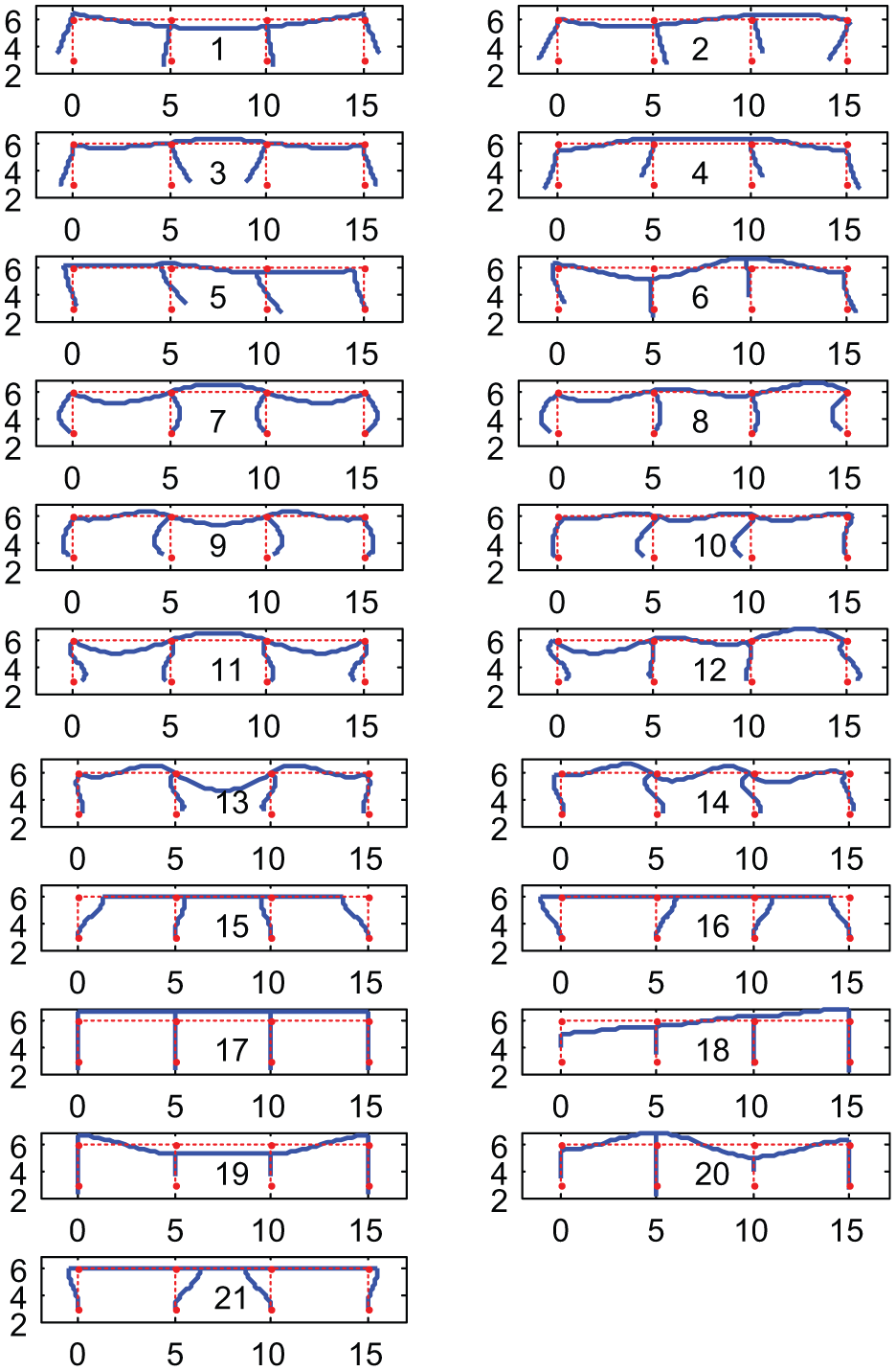
The 21 eigenvectors of substructure 2.
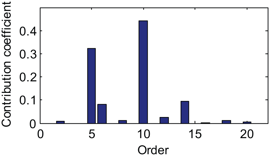
Contribution coefficients about eigen distortions of substructure 2.
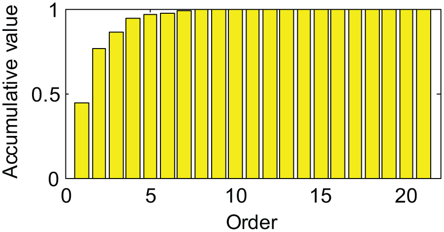
Computed accumulative value
Eigenvalues corresponding to the primary distortions of substructure 2.
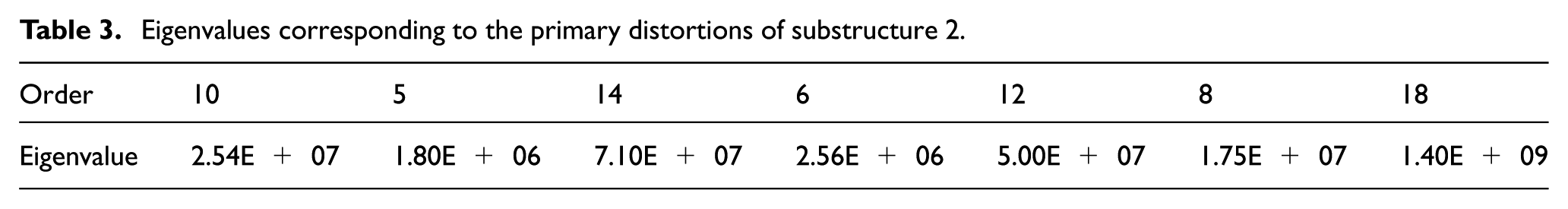
Similarly, the primary distortions of the rest of the substructures can be extracted. The number of the extracted primary distortions of the six substructures, respectively, are [2 7 6 5 5 5]. Compared with 117 virtual distortion vectors, only 30 primary distortion vectors are employed for damage identification, which reduce the computation work a lot during damage optimization.
Construction of FRF
The FRFs of the intact structure at sensor positions are first computed using theoretical model, see Figure 8 (intact), which is then substituted into equation (22) to construct the FRF of the damaged structure. Given the actual damage extents, the FRFs of the damaged structure are constructed using SVDM by only considering primary distortions, see Figure 8 (VDM). It can be seen that the frequencies at the peak points of the constructed FRF and the computed FRF using the damaged finite element method (FEM) model (Figure 8, damaged) are almost the same.
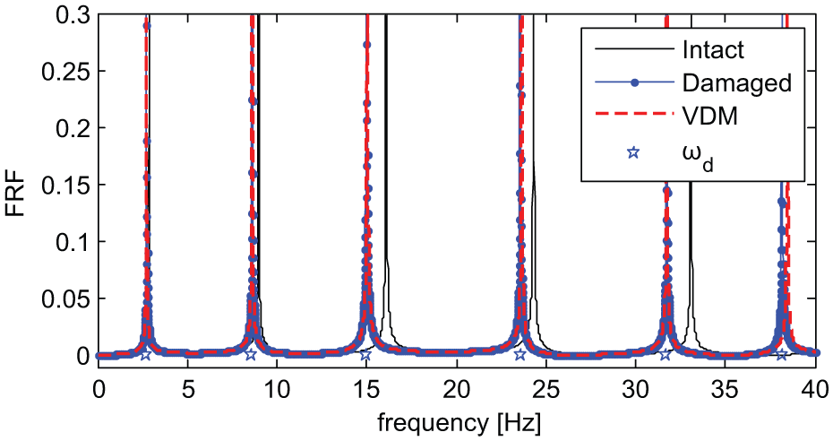
Frequency response functions in different cases.
Furthermore, the natural frequencies of the damaged structure are estimated through the constructed FRF using peak picking method, as listed in Table 4 (VDM). Compared with the natural frequencies computed from the FE model of the damaged structure (Table 4, damaged), the natural frequencies obtained using SVDM are quite accurate, but with each natural frequency a bit bigger than the actual values. It implicates that omitting secondary distortions might cause slight errors in the construction of FRF. Afterward, with regard to each natural frequency, the peak values of the FRF at the six sensors constitute the mode shapes. Figure 9 (VDM) shows the first three estimated mode shapes from the constructed FRF of the damaged structure which are quiet close to those computed using the FE model of the damaged structure (Figure 9, damaged). This further improves the accuracy of the constructed FRF using SVDM.
First six natural frequencies of the damaged structure (Hz).
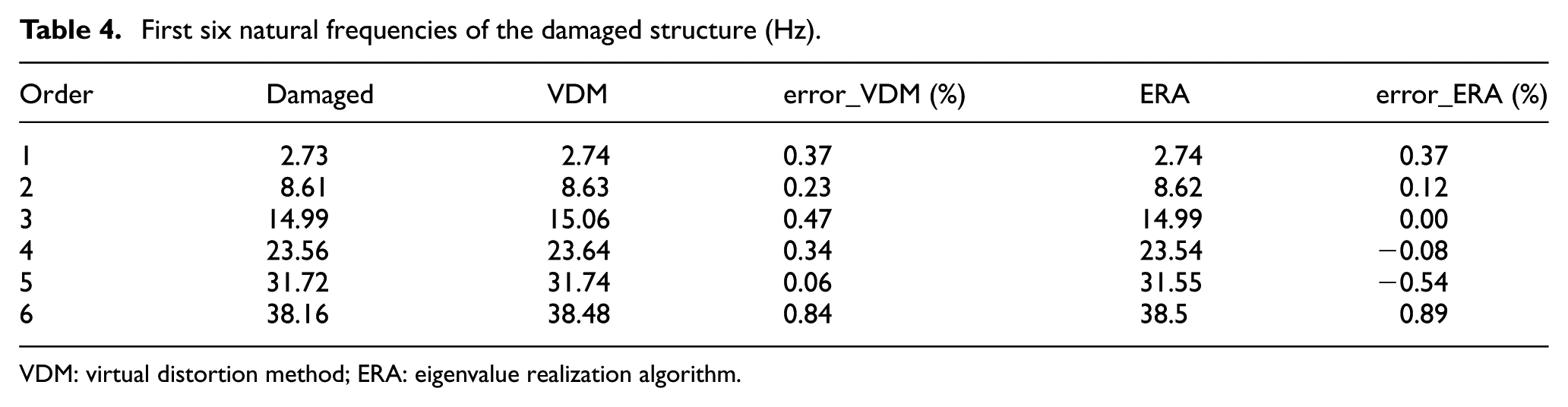
VDM: virtual distortion method; ERA: eigenvalue realization algorithm.
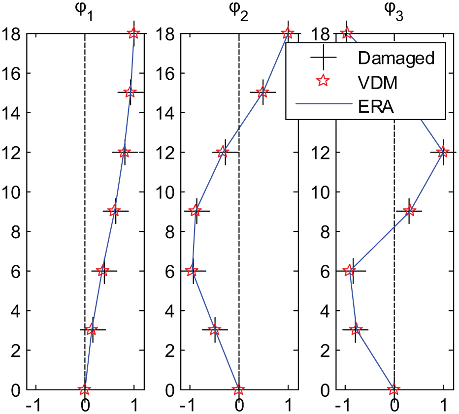
Identified first three mode shapes of the damaged structure.
Substructure damage identification
Making use of the structural natural frequencies and mode shapes, the substructure damages are optimized via the objective function (26), where the identified modal parameters
Identified damage results.
Experimental test
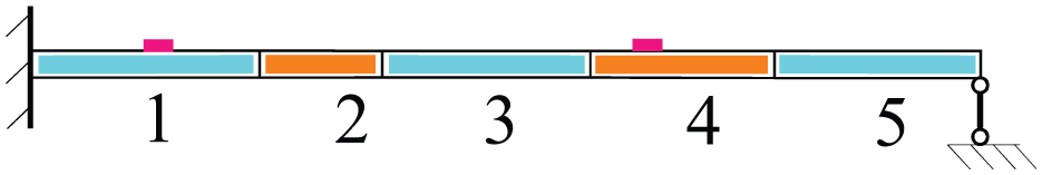
The proposed approach is further tested using an experiment of a cantilever beam as shown in Figure 11. The length of the beam is 136.15 cm with rectangular cross section of 2.7 cm × 0.31 cm, and the Young’s modulus is 70 GPa with density of 2700 kg/m3. The section close to the fixed end is cut evenly to simulate the damage with the cross section reduction of 58%, and thus, the damage extent is 42%. The damaged section length is 10.23 cm.
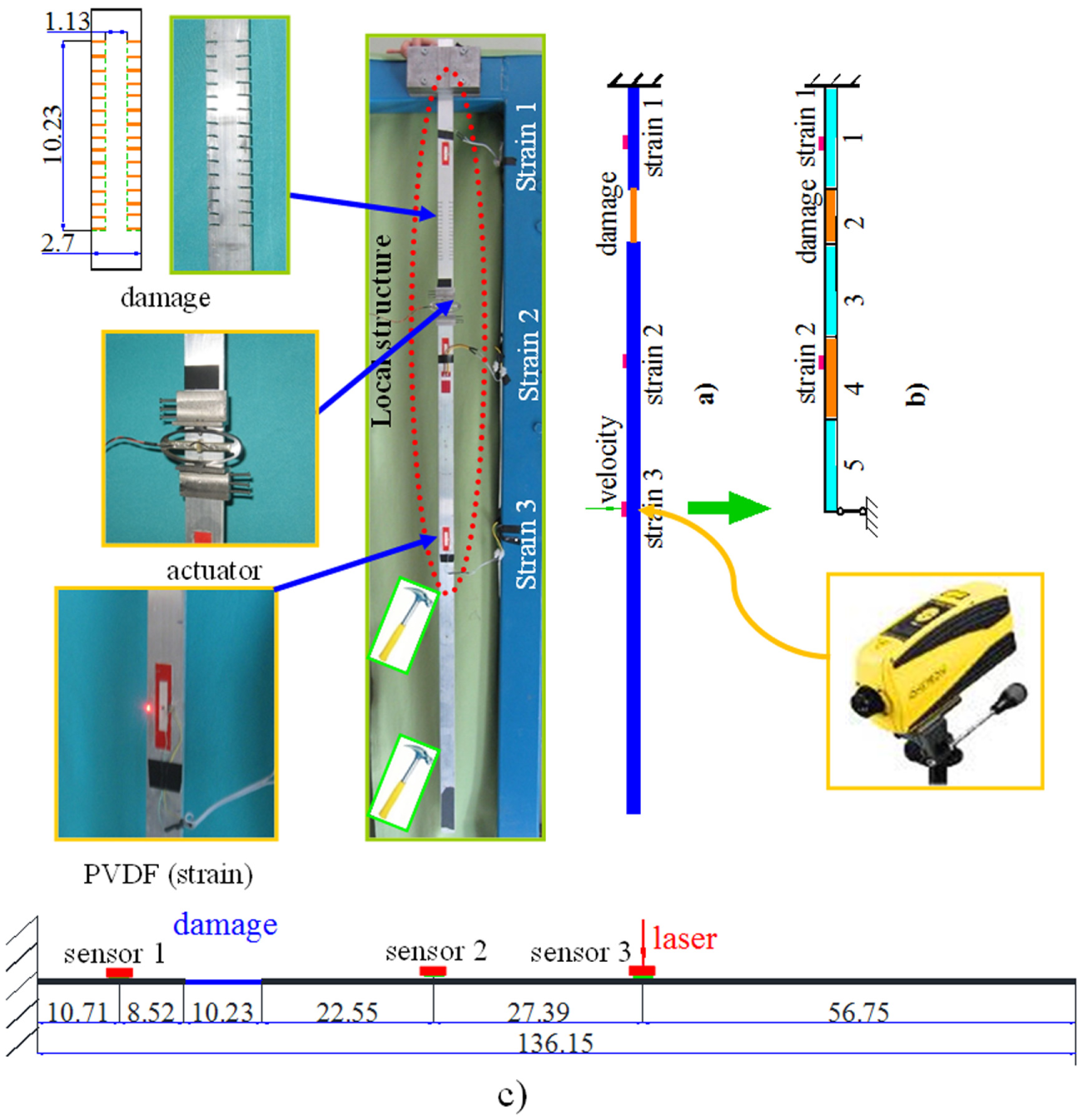
Experiment setup: (a) global structure, (b) isolated structure, and (c) experimental model.
In the experiment, only the upper parts, that is, from the fixed end to the position of sensor 3, are to be monitored, see Figure 11, marked by local structure. Three piezo-electric sensors are glued on the beam to measure the strain responses, shown as strain 1–strain 3 in Figure 11. A laser sensor is used to measure the boundary velocity of the local structure, which is at the position of sensor 3.
Measurements
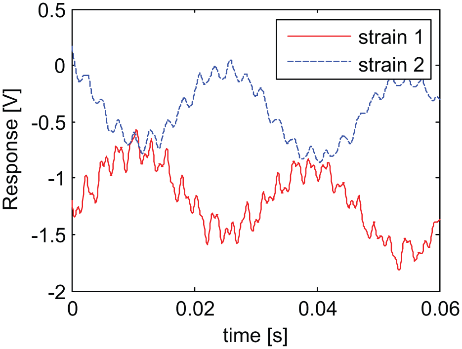
In order to isolate the local structure from the whole system, isolate substructure method (ISM) is employed which is introduced specifically in another article (Hou et al., 2015). According to the requirement of ISM, a hammer excitation is adopted which knocks first inside the local structure twice, then twice inside but close to its boundary, and finally twice outside and far away from the boundary. The excited responses at sensor 1 and sensor 2 are measured and shown in Figure 12.
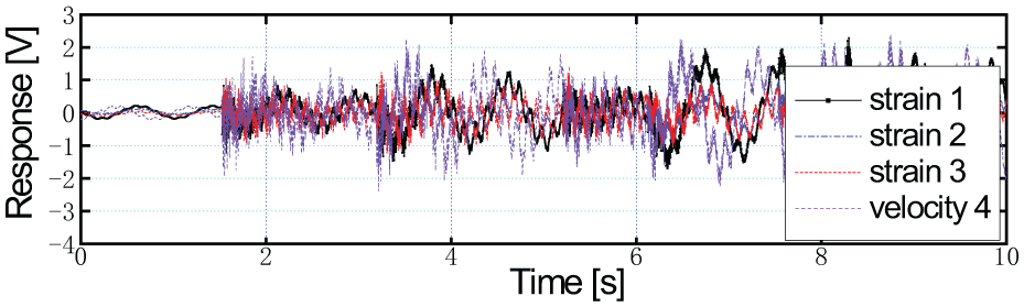
Measured responses.
Figure 13 shows the numerically isolated local structure model, which is fixed at one end with a sliding bearing on the other end. Strain responses of the isolated structure at sensor 1 and sensor 2 are shown in Figure 14 which are constructed using measured responses by implementing the ISM method. Through the constructed responses, the first seven natural frequencies of the damaged isolated structure are identified using eigenvalue realization algorithm, as listed in Table 5 (identified). In addition, Table 5 (damaged FEM) also lists natural frequencies calculated using the FE mode of the isolated structure with actual damage extents which are very close to the identified values. This implies that the local structure is isolated accurately.
Model of the isolated local structure.
Constructed strain responses of the isolated structure.
First seven order frequencies of isolated structure (Hz).
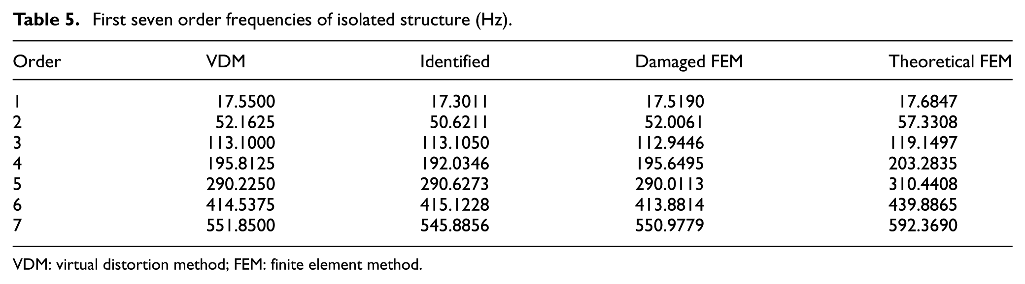
VDM: virtual distortion method; FEM: finite element method.
Damage identification is performed using the equivalent isolated structure instead of the actual structure in the following sections. The isolated structure is divided into five substructures, marked by 1–5 as shown in Figure 13, where the second part is actually damaged.
Extraction of primary distortions
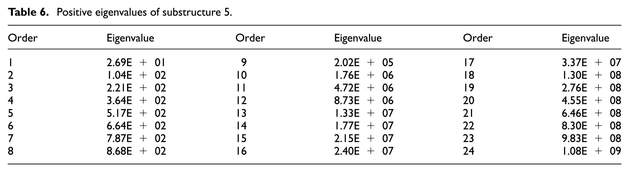
First, primary distortions of each substructure are analyzed and extracted. The stiffness matrix of each substructure is assembled and eigenvalue decomposition is performed on them individually. The number of their positive eigenvalues, respectively, are [27 18 27 27 24], that is to say, there are 123 substructure virtual distortion vectors required to be solved repeatedly during damage optimization. Primary distortions are extracted for identification to reduce the computation work. Here, it only takes substructure 5 as an example to introduce the concrete performance.
Table 6 lists the positive eigenvalues of substructure 5. The corresponding first six eigenvectors are shown in Figure 15. It employs the sum of first seven mode shapes of the intact isolated structure to construct the excitation which are applied on the intact isolated structure model to compute the actual distortion vectors of substructure 5. Figure 16 shows the first six actual distortions. The 24 actual distortion vectors are, respectively, applied as excitations on the intact structure, and thus, respectively, caused 24 groups of structural responses. Figure 17 shows the first six groups of responses at sensor 1. Then with regard to each group of responses, the contribution coefficient is computed individually using equation (23). The computed 24 contribution coefficients are normalized and shown in Figure 18. The accumulative value
Positive eigenvalues of substructure 5.
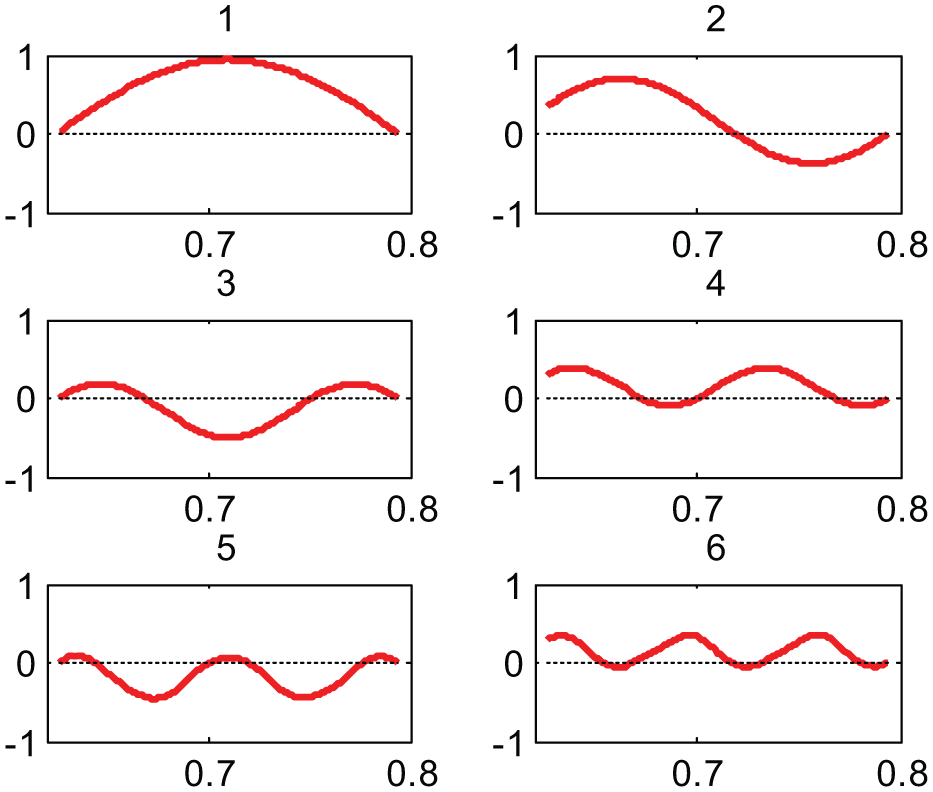
First six eigenvectors of substructure 5.
First six actual distortions of the intact isolated structure.
First six responses of the intact structure at sensor 1 to the actual distortions.
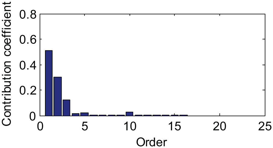
Contribution coefficients about the eigen distortions of substructure 5.
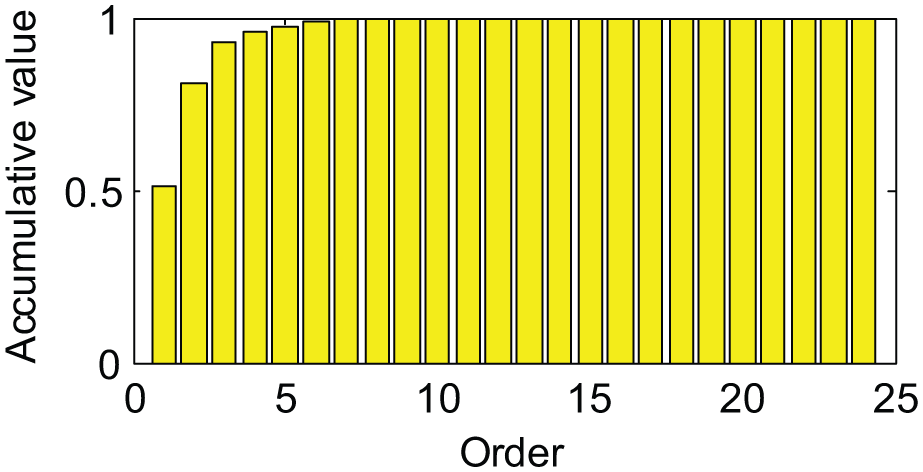
Computed accumulative value
In case of confidence value
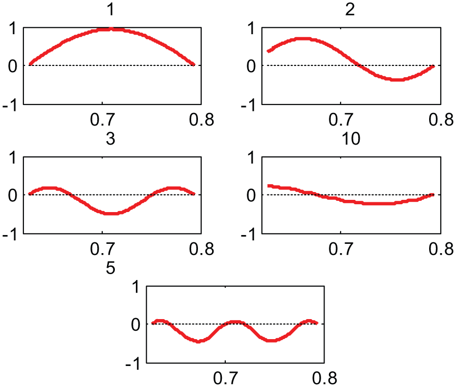
Extracted five primary distortion vectors of substructure 5.
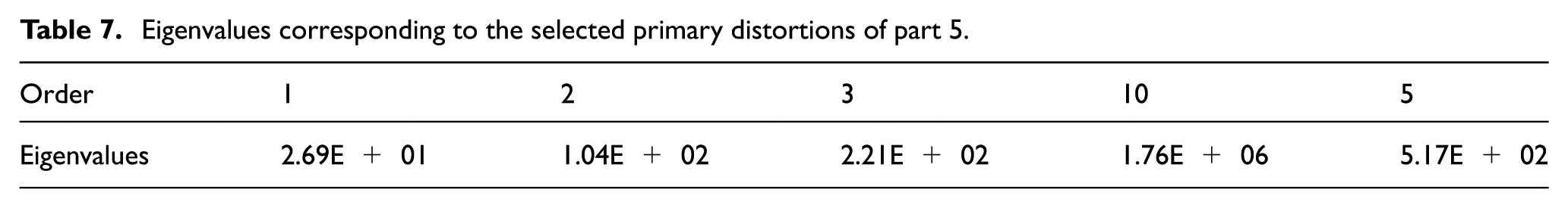
Eigenvalues corresponding to the selected primary distortions of part 5.
Similarly, the primary distortions of the rest of the substructures can be extracted. There are 25 primary distortion vectors in all which are employed for damage identification.
Construction of FRF
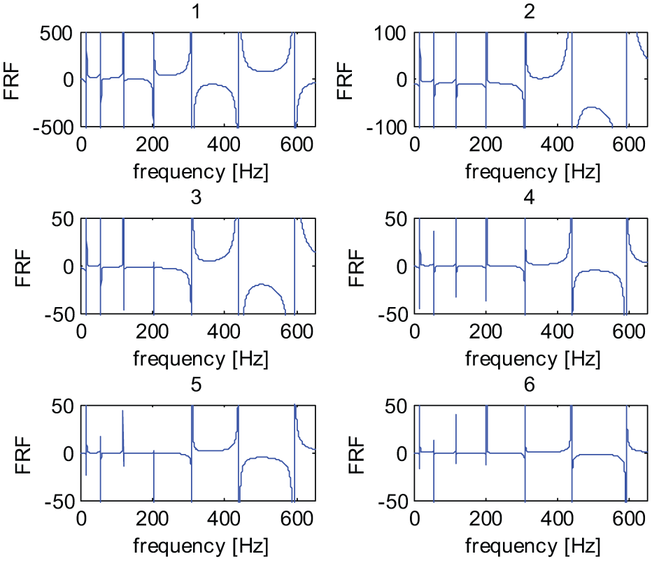
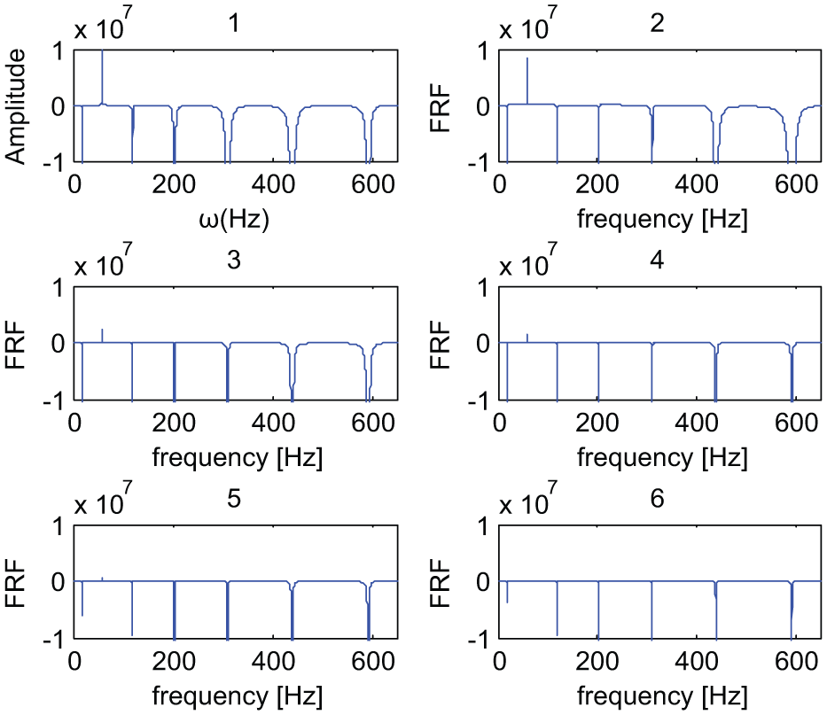
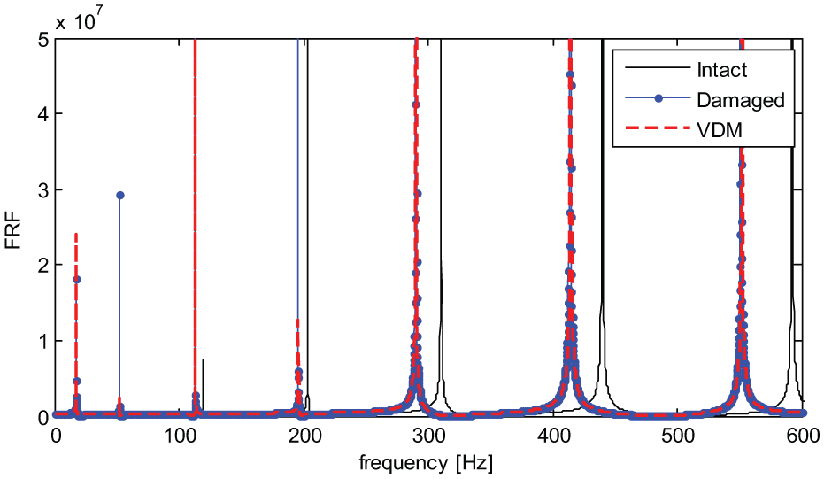
Only the FRF at sensor 1 is taken as an example to verify the construction of FRF using SVDM. First, the FRF of intact isolated structure is computed using the theoretical FE model, as shown in Figure 21 (intact), which is substituted into equation (22) to construct the FRF of the damaged structure. Using the extracted primary distortions, the FRFs of the damaged structure under given actual damage extents are constructed and shown in Figure 21 (VDM). It can be seen that the frequencies at the peak points of the constructed FRF and the FRF computed using the damaged FE model (Figure 21, damaged) are almost the same. The frequencies are then estimated and listed in Table 5 (VDM), which are very close to the values computed using the FE model of the damaged structure (Table 5, damaged FEM). This proves that the FRFs of the damaged structure are constructed accurately using SVDM. Figure 22 shows the constructed FRF of the damage isolated structure using SVDM at sensor 1 and sensor 2.
Frequency response at sensor 1.
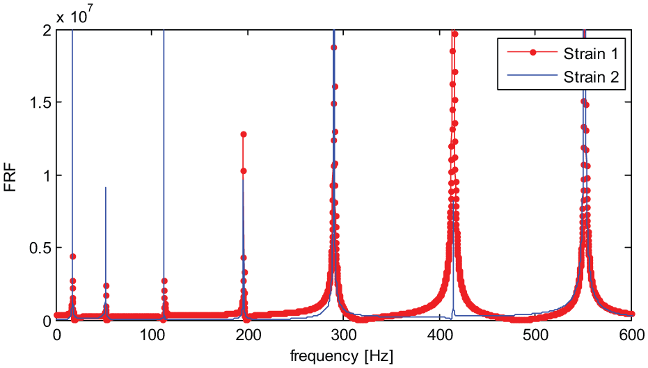
Constructed FRF of the damage isolated structure at two sensors using SVDM.
Damage identification
The substructure damages of the local structure are optimized via the objective function equation (26). The natural frequencies
Substructure damages are optimized by minimizing the objective function. The identified results are shown in Figure 23, of which substructure 5 has the biggest relative error 6.5%. Both the identified damage extents and locations of the rest parts are acceptable.
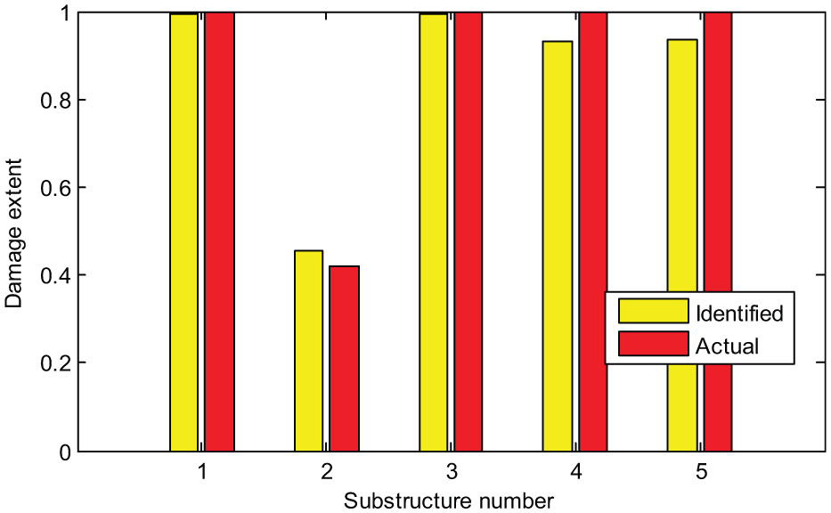
Damage extent.
Conclusion
This article presents an effective method for damage identification in frequency domain based on SVDM. The application of VDM is expanded from simulating element modification to simulating substructure modification, and from time domain into frequency domain through Fourier transform. The computational efficiency of structural reanalysis is increased compared to that of VDM. During the parameter optimization, the FRF of the damaged structure under given damage extents is constructed quickly using the extracted primary distortions of the substructures without a numerical simulation and the repeated assembly of the structural system matrix, which improves the computational efficiency significantly especially for large and complex structure. A numerical model of a six-story frame and an experiment of a cantilever beam are presented to verify the proposed method, where structural damage extents and locations are identified acceptably.
Footnotes
Declaration of Conflicting Interests
The author(s) declared no potential conflicts of interest with respect to the research, authorship, and/or publication of this article.
Funding
The author(s) disclosed receipt of the following financial support for the research, authorship, and/or publication of this article: The authors gratefully acknowledge the support of National Science Foundation of China (NSFC) (51108066), the Fundamental Research Funds for the Central Universities (China) (DC201501050), and Liaoning Provincial Natural Science Fund (2015020621). Financial support of Structural Funds in the Operational Programme-Innovative Economy (IE OP) financed from the European Regional Development Fund-Project “Modern material technologies in aerospace industry” (POIG.0101.02-00-015/08) is gratefully acknowledged.