
Abstract
Carbon-fiber-reinforced polymer grids have received much attention lately because of many advantages. The force transfer behavior and development length of carbon-fiber-reinforced polymer grid reinforcement were evaluated using a pull-out test method. A total of 18 pull-out specimens of carbon-fiber-reinforced polymer grid reinforcement were tested under monotonic static loading, and the investigated parameters included the concrete compressive strength, the number of embedded transverse bars, with or without transverse bars, and the number of adjacent longitudinal bars. The slips between the reinforcing carbon-fiber-reinforced polymer grids and the concrete were measured at both the free end and the loaded end during the whole loading process. The test results indicated that first, the concrete compressive strength and the adjacent longitudinal bars had little influence on the force transfer behavior, second, the wedge action of the transverse bars was very important for transferring force; thus, increase in number of embedded transverse bars increased the force transfer stiffness and reduced the slippage. In the case of tested carbon-fiber-reinforced polymer grids, three embedded transverse bars equal to embedment length of 150 mm were sufficient to develop full tensile strength. Based on this experimental investigation, the preliminary design principles were also discussed.
Introduction
Fiber-reinforced polymer (FRP) composites are composed of high-strength fibers enclosed in a resin matrix which serves to bind the fibers into a single structure. In recent years, FRP composites are gaining acceptance as non-metallic reinforcement for concrete structures where high corrosion resistance or magnetic transparency is required. In addition, they are also attractive in this application because of the excellent tensile strength-to-weight characteristic and fatigue resistance. The use of FRP instead of steel provides a reliable way to reduce life cycle costs of concrete structures, avoiding costly rehabilitation and maintenance. Research and development of FRP composites in the civil infrastructure have progressed significantly (Hollaway, 2010), and it has been well established that in the foreseeable future, FRP composites will be utilized with great advantage if they are employed innovatively.
Concrete structures exposed to deicing salts and marine environments require the non-corrodible and durable nature of FRP. Yet, glass-fiber-reinforced polymers (GFRP) are very susceptible to saltwater. If saltwater comes in contact with glass fibers, it will degrade them and can harm them in a short period of time. The alkaline attack can cause complete breakage of external glass fibers (Micelli and Nanni, 2004). Although the glass fibers have protective resin against such attack, cracking of the resin is easy so that saltwater is allowed to penetrate and harm the fibers. However, carbon fibers are immune to saltwater and therefore suitable for structures in severe environmental conditions, which means carbon fibers do not show damage against alkaline solutions (Micelli and Nanni, 2004) conducted tests on both GFRP and carbon-fiber-reinforced polymer (CFRP) bars for durability in various environments and revealed problems with GFRP bars but no problems with CFRP bars. A reduction in the tensile strength of 41% for GFRP bars was observed after alkali exposure for 42 days at a temperature of 60°C, while no significant loss of tensile strength for CFRP bars was observed under the same conditions. In addition, the tensile strength and modulus values of CFRP are relatively higher than the other three kinds of FRPs in the construction industry, including glass (GFRP), aramid (aramid-fiber-reinforced polymer (AFRP)), and basalt (basalt-fiber-reinforced polymer (BFRP)).
The two-dimensional CFRP grids used in this study are made from high-performance, orthogonally intersecting, continuous carbon fibers impregnated within a resin matrix. The typical CFRP grids are available in rectangular sheets which are composed of orthogonally intersecting longitudinal and transverse bars with rigid nodes, as shown in Figure 1. In cross section, the grid bars are crudely rectangular with smooth top and bottom surfaces. Typically, the longitudinal-bar-spacing and transverse-bar-spacing are equal, and all the grid bars have equivalent material properties. Figure 2 visually displays that the CFRP grids are made from continuous impregnated carbon fiber alternating in two directions to form a cross-laminate grid structure with rigid nodes. The rigid nodes and transverse bars assure the mechanical anchorage of the longitudinal bars, which means functionally, longitudinal and transverse bars provide tensile reinforcement and force transfer in concrete, respectively.

Typical two-dimensional CFRP grids.
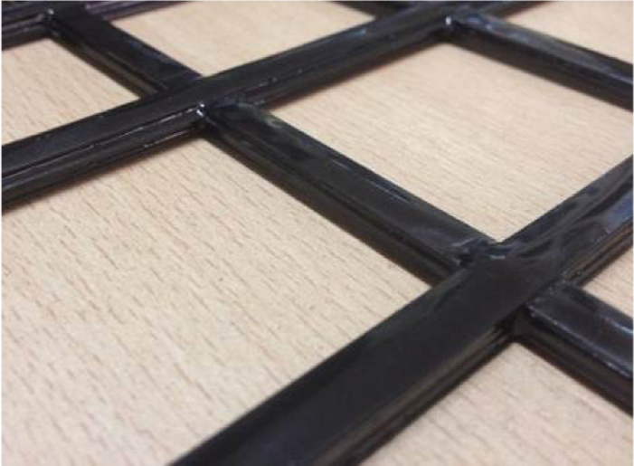
CFRP grids with rigid nodes used as concrete reinforcement.
In a typical CFRP-grid-reinforced concrete flexural member, the tension force carried by the reinforcement balances the compression force in the concrete. The tension force is transferred to the reinforcement through the force transfer between the reinforcement and the surrounding concrete; force transfer in the CFRP grids is a combination of bond on longitudinal bars and wedge action on transverse bars. Arguably, CFRP grids transfer force to concrete primarily through anchorage provided by the transverse bars, as they are smooth between grid joints. CFRP grids have been used as tensile reinforcement in concrete beams, slabs, or bridge decks under experimental investigations (Matthys and Taerwe, 2000; Rahman et al., 2000; Yost et al., 2001; Yost and Schmeckpeper, 2001; Zhang et al., 2004), and the behavior of the flexural members indicated the viability and effectiveness of CFRP grid reinforcement. It was reported that CFRP grids were a potentially viable replacement for steel as tensile reinforcement for concrete structural members, and the use of CFRP grids as flexural reinforcement resulted in brittle failure as CFRP has no yield point and is linear elastic to failure. In addition, it is necessary to clarify that grid-shaped CFRP reinforcement with weak intersecting nodes, which cannot restrain the relative motion between longitudinal bars and transverse bars, is also available and is used in concrete primarily for crack control and confinement (Michael, 2006; Shao and Mirmiran, 2007). In this article, the grid-shaped CFRP reinforcement with weak intersecting nodes will not be discussed, as the transverse bars are ineffective for force transferring in this case.
Based on the success achieved with respect to tensile reinforcement for concrete, it is natural to investigate the development length of CFRP grids as an important structural property in the design of CFRP-grid-reinforced structures. Limited study has been conducted on the development length of CFRP grids in concrete. Nevertheless, the design equations for calculating the development lengths of straight and hooked FRP bars have been proposed by the American Concrete Institute (ACI) standard ACI 440.1R-06 (2006). These development length equations are based on linear regression from experimental database including 269 tests of straight FRP bars (Wambeke and Shield, 2006) and 36 tests of hooked FRP bars (Ehsani et al., 1996). However, the guidelines available in ACI 440.1R-06 with respect to the development length of FRP bars cannot be directly utilized for CFRP grids due to the different force transfer mechanism.
A rational design guideline for the development length of CFRP grid reinforcement needs to be developed to aid in the further application of CFRP grids. The experimental research described herein focused on the force transfer behavior and development length of CFRP grids with rigid nodes. A total of 18 pull-out tests were conducted, and the experimental variables included the concrete compressive strength, the number of embedded transverse bars, with or without transverse bars, and the number of adjacent longitudinal bars. Detailed results of the experiments were presented. Based on these data, analytical expressions have been proposed for the force transfer behavior of reinforcing CFRP grids to concrete, and the future work has also been discussed to develop acceptable design recommendations for the anchorage of CFRP grids in concrete.
Experimental program
The most popular and extensively used test methods to assess the force transfer behavior and to explore the development length of internal reinforcement are the beam-end test and pull-out test (ACI 440.3R, 2004). The beam-end test has the advantage of realistically simulating the stress distribution in a flexural-reinforced concrete member, but it requires a complex test setup and is relatively expensive to conduct. For pull-out test, the compressive reaction force is applied directly to the surface of the concrete of the specimen, thus inducing compressive stress surrounding the reinforcement, which may artificially enhance the force transfer capacity. However, it is easy to be implemented. The pull-out test method was employed for this project. A total of 18 pull-out specimens were constructed and tested under static monotonic loading. The experimental data were collected during each test, including the applied tensile load, the loaded-end slip, and the free-end slip.
Design of specimens
The CFRP grids in this study were manufactured by the Central Research Institute of Building and Construction of China MCC Group. As shown in Figure 2, the nominal cross-sectional area and bar spacing of the CFRP grids provided by the manufacturer were 14 mm2 and 50 mm, respectively. Three concrete compressive strength and six CFRP grid reinforcement shapes were used for a total of 18 different specimens. The six different shapes of tested CFRP grids are shown in Figure 3, which were designed to investigate the effects of the number of embedded transverse bars (embedment length), with or without transverse bars, and the number of adjacent longitudinal bars on the force transfer behavior. Three pull-out specimens with different concrete compressive strength were used for each shape of CFRP grid reinforcement to evaluate the effect of concrete compressive strength on the force transfer behavior. By careful placement of the reinforcing CFRP grids prior to casting, the dimensions and CFRP grid arrangements of the various pull-out specimens are shown in Figure 4. The cross-sectional dimensions of all concrete blocks were 150 × 150 mm2 with the CFRP grids located in the centers, while the longitudinal dimensions were various according to the embedment length of different CFRP grid reinforcements. As can be seen in Figure 4, the specimen identification scheme is as follows: the first number indicates the target concrete compressive strength in MPa, the second number is the number of embedded transverse bars: the letter denotes with or without transverse bars (Y, Yes; N, No), and the third number is the number of adjacent longitudinal bars. For example, 32Y2 represents a specimen cast with 30 MPa concrete, two embedded transverse bars, and two adjacent longitudinal bars.

Shapes of tested CFRP grid reinforcement: (a) 32Y2, 42Y2, 52Y2; (b) 33Y2, 43Y2, 53Y2; (c) 34Y2, 44Y2, 54Y2; (d) 34Y0, 44Y0, 54Y0; (e) 35Y2, 45Y2, 55Y2; and (f) 30N0, 40N0, 50N0.
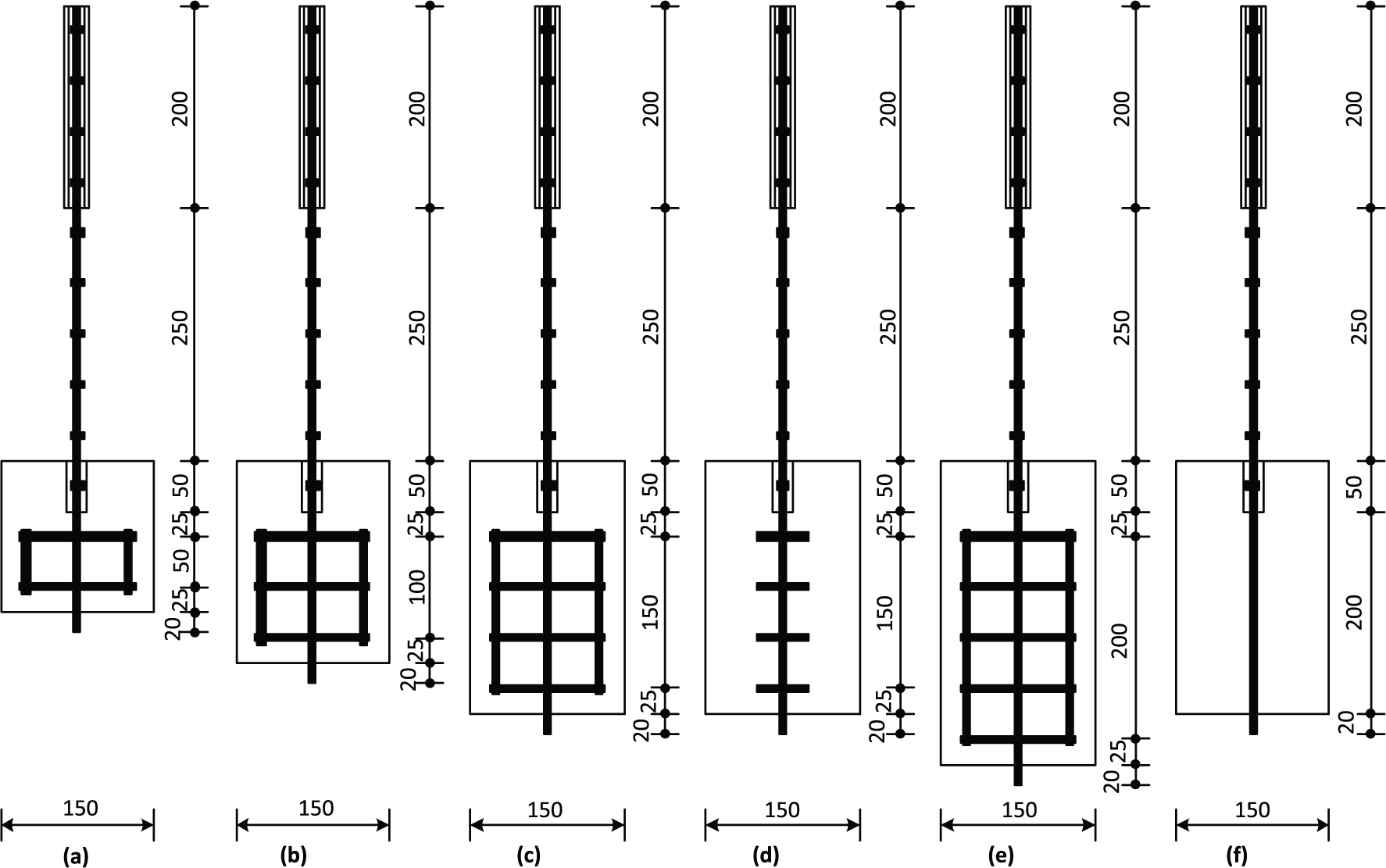
Details of pull-out specimens (dimensions in mm): (a) 32Y2, 42Y2, 52Y2; (b) 33Y2, 43Y2, 53Y2; (c) 34Y2, 44Y2, 54Y2; (d) 34Y0, 44Y0, 54Y0; (e) 35Y2, 45Y2, 55Y2; and (f) 30N0, 40N0, 50N0.
In order to reduce the influence of the compression zone near the supported surface of concrete blocks on the pull-out test results, the first 50 mm of the reinforcing CFRP grids was debonded using plastic tube at the loaded end for all specimens. The tested longitudinal bar of CFRP grid reinforcement was extended 20 mm from the free end to instrument the Linear Variable Differential Transformer (LVDT). The loaded end of the CFRP grid reinforcement was fitted with an anchoring steel tube filled with pure polymer resin, which was capable of transmitting load with no excessive slip. The steel tube was used as a grip to pull the CFRP grids embedded in the concrete. In practice, the region of the reinforcing CFRP grids in the grip must be protected against crushing because FRP composites are very weak for loads applied transverse to the fiber direction.
Material properties
The rectangular cross-sectional width and depth measured of the CFRP grids used in this study are 7 (±0.5) and 5 mm, respectively; therefore, the actual cross-sectional area is approximately 35 mm2. The manufacturing process used in forming the CFRP grids in this study makes them have around 50% carbon fibers mixed with 50% polyester resin by volume. As fibers in FRP are the main load-carrying constituent, it should be noted that the carbon fibers in the CFRP grids mainly distribute on four layers of the cross section, and the dimensions of each layer are 7 (±0.5) mm wide and 0.5 mm thick, which is attributed to the special production process features. Thus, the nominal cross-sectional area of these CFRP grids provided by the manufacturer is 14 mm2, calculated by 4*(7*0.5) mm2. It should be further noted that the elastic modulus and the tensile strength of the CFRP grids are dependent on the definition of cross-sectional area. In order to facilitate the determination of the usual tensile properties of the CFRP grids, the nominal cross-sectional area of 14 mm2 provided by the manufacturer was used in this study.
The tensile properties, including the ultimate tensile strength, the modulus of elasticity, and the rupture strain, were measured by subjecting the tested CFRP grids to uniaxial tension test. Proposed guide test methods including the calculating equations for determining the tensile properties of CFRP grids are available in ACI standard ACI 440.3R-04 (2004). A total of five tension tests of CFRP grids taken from the same lot as the pull-out specimens were performed on a universal testing machine, as shown in Figure 5. A typical stress–strain relationship is shown in Figure 6. Like other FRP products, the CFRP grids in tension exhibited a linearly elastic stress–strain relationship until failure of rupture. The detailed test results for tensile properties of the CFRP grids are presented in Table 1. Usually, a normal (Gaussian) distribution is assumed to represent the tensile strength of a population of FRP bar specimens (Kocaoz et al., 2005). Therefore, the coefficient of variation for the ultimate tensile strength was 1.6%, the modulus of elasticity was 1.3%, and the rupture strain was 1.7%. All the Coefficient of Variation (COVs) were low, which was attributed to the stable manufacturing technique. The guaranteed tensile strength, defined as the mean tensile strength of a sample of test specimens minus three times the standard deviation, was 1963 MPa.
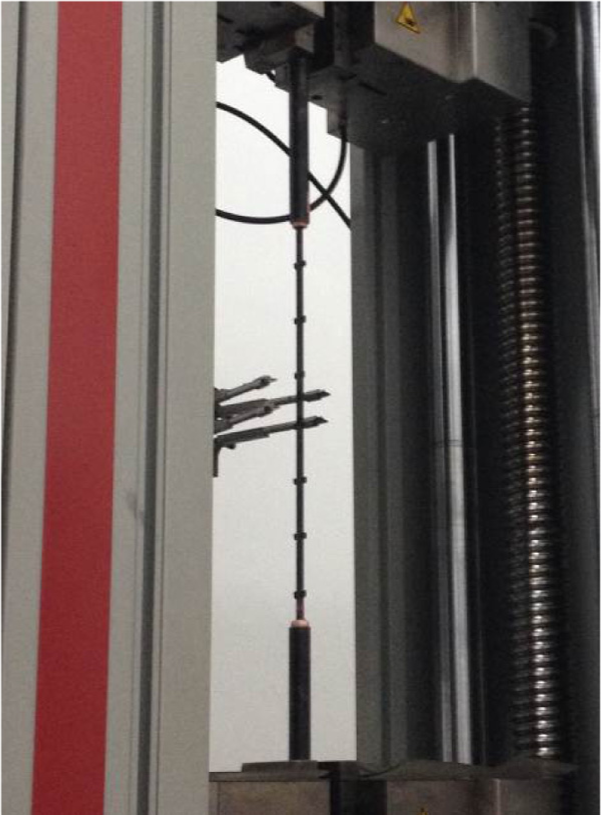
Tension test of typical CFRP grids.
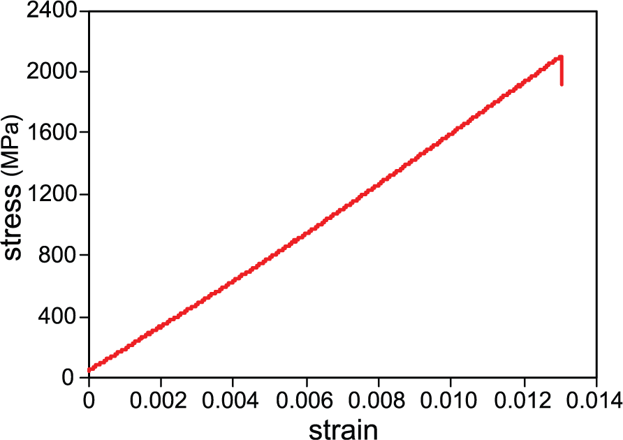
Typical tensile stress–strain relationship of the tested CFRP grids.
Tension test results of CFRP grids.
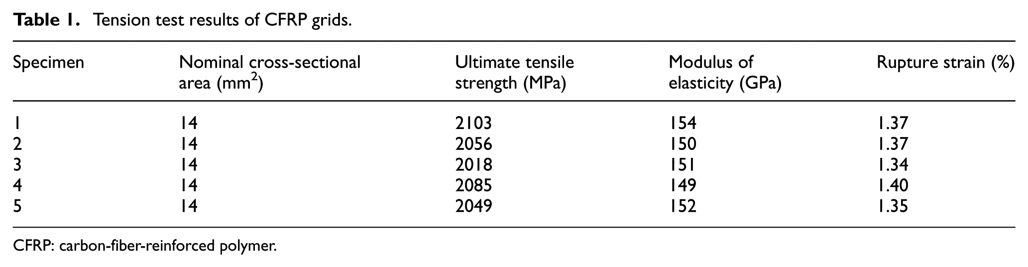
CFRP: carbon-fiber-reinforced polymer.
To analyze the influence of concrete strength on the force transfer behavior, the concrete used in this study was obtained from a ready mix plant and designed to have three different target cubic compressive strengths of 30, 40, and 50 MPa, having 20 mm aggregate size. Therefore, the 18 specimens were cast in three batches, and the mean concrete compressive strength of each batch of concrete was determined through compressive tests on three control samples (150 × 150 × 150 mm3), which were cast at the same time and cured under the same condition as the specimens. All the pull-out specimens were tested at an age of 28 days, and the mean concrete cubic compressive strength values on the day of testing are presented in Table 2.
Pull-out test results of CFRP grids.

CFRP: carbon-fiber-reinforced polymer; PO: pulling out; GF: grid fracture.
Test setup and instrumentation
The test setup for all the pull-out specimens is shown in Figure 7. Due to the low shear strength of the CFRP grids, care must be taken not to harm the reinforcing CFRP grids during placement of the specimens in the test setup. Prior to each pull-out test, the setup was installed with great care to ensure that the CFRP grid reinforcement was under uniaxial tensile load. The pull-out specimens were tested on the platform of a steel frame with a hole in the middle. The grip of each specimen was fitted to the anchorage device, so the applied loads were transmitted from the hydraulic jack to the CFRP grids through these grips. The hydraulic jack was connected to a hand pump which was used to manually control the applied load. A steel plate was installed between the hydraulic jack and the concrete block to minimize any effects of eccentric loading by enlarging bearing area on the concrete block. A small glass plate was mounted on the free end of CFRP grid reinforcement with epoxy glue to provide a large smooth reference surface for the LVDT.
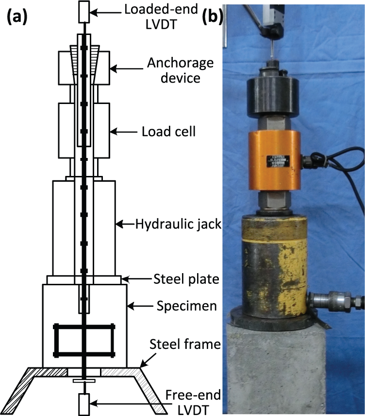
Test setup for pull-out specimens. (a) schematic view (b) appearance.
Monotonic static pull-out loading was gradually applied to the CFRP grid reinforcement in approximately constant increments until splitting failure of concrete, pulling out of CFRP grids from the concrete, or fracture of CFRP grids was reached. The load value applied to the tested CFRP grids was measured by the load cell. Meanwhile, the slippage between the reinforcing CFRP grids and the concrete was measured by two LVDTs, reading accurately to 0.01 mm, installed at the loaded end and the free end of CFRP grid reinforcement, respectively, as shown in Figure 7. An automatic data acquisition control system was used to record the values of the applied load, the loaded-end slip, and the free-end slip at a frequency of 1 Hz.
Test results and discussions
Under monotonic static pull-out loading, the load values, the loaded-end slips, and the free-end slips were obtained during the whole loading process. Test results of the 18 pull-out specimens were examined to evaluate the force transfer behavior and the development length of CFRP grids in concrete. The influence of the concrete compressive strength, the number of embedded transverse bars, with or without transverse bars, and the number of adjacent longitudinal bars on the force transfer behavior was analyzed in this section. Overall, a preliminary design provision for the development length of CFRP grid reinforcement was introduced.
Test results of pull-out specimens
The tensile stress corresponding to the applied load was calculated as the tensile load applied on the CFRP grids divided by the nominal cross-sectional area of 14 mm2. The displacement measured by the LVDT fitted to the free end of the CFRP grids was the free-end slip of the CFRP grids with respect to the surrounding concrete. However, the displacement measured by the LVDT fitted to the loaded end contained two main components: (1) the elastic elongation of the reinforcing CFRP grids itself and (2) the loaded-end slip of the CFRP grids with respect to the surrounding concrete. Therefore, the actual loaded-end slip can be obtained by deducting the elongation using the following calculation

where LVDT is the displacement measured by the LVDT fitted to the loaded end; P is the applied tensile load at a given time; L is the length of the unbonded region of the reinforcing CFRP grids taken as 300 mm for all specimens, as shown in Figure 4; E is the modulus of elasticity of the tested CFRP grids taken as the average from the tension test results; and A is the nominal cross-sectional area of 14 mm2 provided by the manufacturer.
Figures 8 to 10 show curves for all pull-out specimens of the tensile stress versus the free-end and the loaded-end slips, illustrating the force transfer behavior for the different pull-out specimens. Note that the slip of CFRP grids embedded without transverse bars (specimens 30N0, 40N0, and 50N0) was a relatively large part of these curves; thus, free-end slips and loaded-end slips more than 4 and 6 mm, respectively, of specimens 30N0, 40N0, and 50N0 were not plotted. As seen in the curves, the loaded ends started to slip from the beginning of the loading, while the free ends started to slip at different tensile stress levels. Some characteristic values of the test results for all pull-out specimens are presented in Table 2, in order to compare the performance of different pull-out specimens. In the case of CFRP grid reinforcement, the force transfer is provided by chemical adhesion and natural roughness at the reinforcement–concrete interface of longitudinal bars and wedge action of the transverse bars (Yost, 1993). The load at first free-end slip is the load at which the chemical adhesion between the longitudinal bar and the concrete completely breaks. As can be seen, first, the maximum stress was around the ultimate tensile strength for specimen whose failure mode was CFRP grids’ fracture and was lower than the ultimate tensile strength for specimen whose failure mode was CFRP grids’ pulling out. Second, three transverse bars embedded in concrete were sufficient to develop full tensile strength of the tested CFRP grids. Third, increase in the number of embedded transverse bars increased the force transfer stiffness and reduced both slips.
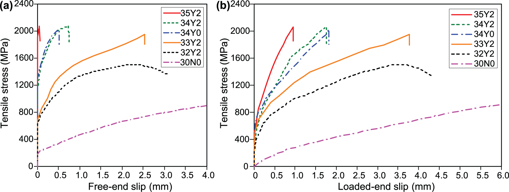
Stress–slip curves for CFRP grids cast with 30 MPa targeted strength concrete for (a) free end and (b) loaded end.
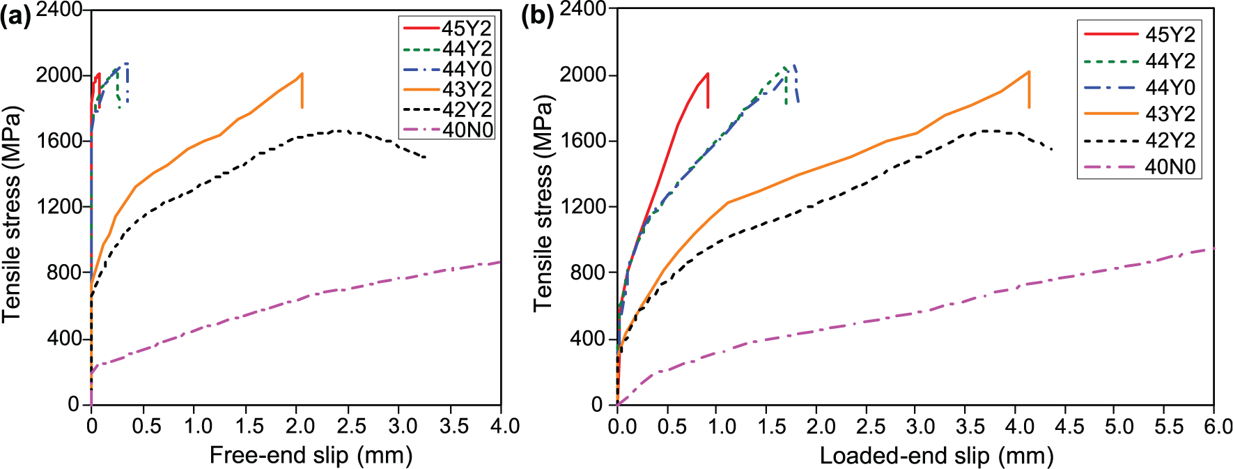
Stress–slip curves for CFRP grids cast with 40 MPa targeted strength concrete for (a) free end and (b) loaded end.
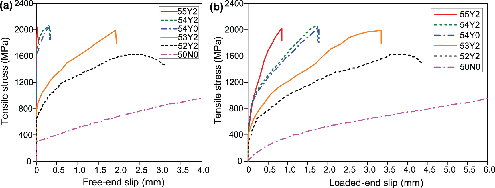
Stress–slip curves for CFRP grids cast with 50 MPa targeted strength concrete for (a) free end and (b) loaded end.
Failure of the pull-out specimens occurred either by CFRP grids pulling out of the concrete or by CFRP grids’ fracture, as shown in Figure 11. No concrete splitting was observed. The failure mode for each pull-out specimen is also listed in Table 2. As the number of embedded transverse bars increased, the failure mode changed from pulling out to grid fracture. The majority of the pull-out specimens failed by fracture of the reinforcing CFRP grids. In addition, CFRP grids’ fracture failure was sudden and CFRP grids’ pulling out failure ended with large slips.
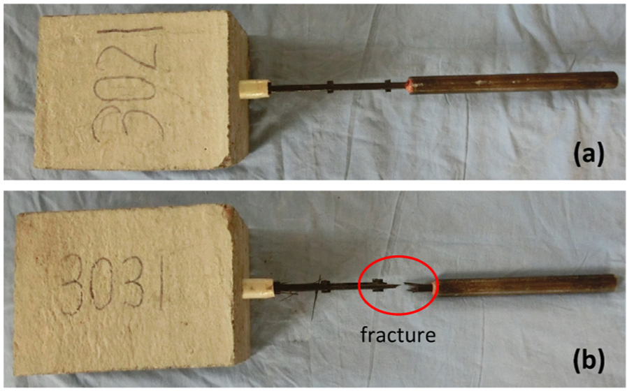
Typical failure mode: (a) pulling out and (b) grid fracture.
Influence of experimental parameters
Effect of concrete compressive strength
To determine the effect of concrete strength on the force transfer behavior of reinforcing CFRP grids, designed concrete cubic compressive strengths of 30, 40, and 50 MPa were selected for each shape of CFRP grid reinforcement, such as specimens 32Y2, 42Y2, and 52Y2, which had the same design experimental parameters except for the concrete compressive strength. As shown in Figures 8 to 10 and Table 2, however, concrete compressive strength has little influence on the force transfer behavior for specimens with the same shape of CFRP grids’ reinforcement type, since the stress versus free-end and loaded-end slip curves were found to be similar. This most likely reflects that the tensile strength of concrete, which is approximately proportional to the square root of its compressive strength (ACI 318; ACI, 2011), is considered an important parameter in force transfer behavior on condition that force transfer failure is caused by tensile splitting of the concrete along the reinforcing CFRP grids. As presented earlier, all the pull-out specimens failed with no sign of concrete splitting.
Effect of number of embedded transverse bars
With the help of the wedge mechanism provided by the transverse bars, the force transfer between the reinforcing CFRP grids and the concrete was effective and allowed development of full tensile strength of the CFRP grids. To determine the effect of the number of embedded transverse bars on the force transfer behavior and the development length of reinforcing CFRP grids, the designed number of embedded transverse bars of 2, 3, 4, and 5 were selected. For example, specimens 32Y2, 33Y2, 34Y2, and 35Y2 had the same design experimental parameters except for the number of embedded transverse bars. As shown in Figures 8 to 10 and Table 2, the number of embedded transverse bars has a significant influence on the force transfer behavior. As expected, the slips corresponding to the maximum stress decreased with increase in the number of embedded transverse bars. Two embedded transverse bars were able to develop about 75% tensile strength of the tested CFRP grids. Although three embedded transverse bars allowed development of full tensile strength of the tested CFRP grids, the force transfer stiffness (slope in the stress–slip curves) of specimens with three embedded transverse bars was lower than specimens with four and five embedded transverse bars, as there was a relatively larger slip which occurred at the maximum load.
Effect of with or without transverse bars
One of the most critical issues in the applicability of FRP grid reinforcement in concrete is the force transfer capacity. As can be seen, the CFRP grid reinforcement in this study has good force transfer capacity which is provided by the chemical adhesion and friction force of the longitudinal bars and the wedge action of the transverse bars (Yost, 1993). However, the force transfer capacity of CFRP bar reinforcement with smooth surface depends completely on the chemical adhesion and friction force. In order to understand the force transfer mechanism, CFRP grid reinforcement with transverse bars and CFRP grid reinforcement without transverse bars were tested, such as specimens 34Y2 and 30N0, which had the same design experimental parameters and embedment length of 200 mm, except for the existence of the embedded transverse bars. As shown in Figures 8 to 10 and Table 2, the contribution of the transverse bars to the force transfer behavior was significant. The reinforcing CFRP grids without transverse bars developed only around half tensile strength and the free-end slip corresponding to the maximum stress reached almost 10 mm; moreover, the stress at first free-end slip was only 305 MPa at most. However, the reinforcing CFRP grids with transverse bars developed full tensile strength, the free-end slip corresponding to the maximum stress reached a maximum of 0.73 mm, and stress at first free-end slip was 1154 MPa at least. Therefore, it is evident that the force transfer of the reinforcing CFRP grids is a combination of chemical adhesion and friction force on longitudinal bars and wedge action on transverse bars and is largely dependent on the transverse bars.
Effect of number of adjacent longitudinal bars
As CFRP grid reinforcement has continuous and integrated structure, the adjacent longitudinal bars of the tested CFRP grids are likely to have an influence on the force transfer behavior of the tested longitudinal bar. To investigate this influence, designed number of adjacent longitudinal bars of 2 and 0 were selected, such as specimens 34Y2 and 34Y0, which had the same design experimental parameters except for the number of adjacent longitudinal bars. Based on the test results shown in Figures 8 to 10 and Table 2, the force transfer behavior of the tested longitudinal bar is independent of the adjacent longitudinal bars, as the stress versus free-end and loaded-end slip curves were found to be very similar. Therefore, it is reasonable to expect that the longitudinal bar of CFRP grids develop force transfer to concrete through anchorage provided by the transverse bars close to the intersections, as well as chemical adhesion and natural roughness of the longitudinal bar itself.
Proposed design provision
Overall, force transfer behavior of the 18 pull-out specimens was examined to develop some preliminary design guidelines. From the test results, three embedded transverse bars equal to embedment length of 150 mm can be considered as the development length for the tested CFRP grids, since all the pull-out specimens whose number of embedded transverse bars was equal or more than three were failed by CFRP grid reinforcement fracture without large slippage. However, CFRP grid reinforcement is generally available in a number of different cross-sectional properties, bar spacing, and fiber types. Additional pull-out tests for different-sized CFRP grid reinforcement are required to determine the corresponding development length, before comprehensive equations for calculating development length can be proposed. It is conservative to propose that the pull-out test method described in this article is suggested to determine the required development length for each type of FRP grid reinforcement, and the principal variable is the number of embedded transverse bars. In addition, the minimum tension lap splice length for FRP bars is recommended by ACI standard ACI 440.1R-06 (2006) as 1.3 times the development length. Based on the test results in this study, it should be noted that CFRP grid reinforcement has better force transfer behavior with the help of transverse bars. Therefore, it is conservative to take the minimum tension lap splice length of CFRP grid reinforcement as 1.3 times the development length.
Conclusion
A total of 18 pull-out specimens of CFRP grids were tested, and the tested CFRP grid reinforcement had nominal cross-sectional area and bar spacing of 14 mm2 and 50 mm, respectively. The test method mentioned in this article specified the test requirements for determining the development length of CFRP grids in concrete by pull-out testing. Based on the experimental and analytical study in this article, the following conclusions can be drawn:
For the failure modes of pulling out and fracture of the CFRP grid reinforcement, concrete compressive strength has little influence on the force transfer behavior of the tested CFRP grids possibly because no sign of concrete splitting was observed.
For FRP grid reinforcement embedded in concrete, force transfer behavior depends to a great extent on the number of embedded transverse bars. Increase in the number of embedded transverse bars increases the force transfer stiffness and reduces the slippage. In the case of tested CFRP grids, the contribution of mechanical anchorage provided by the transverse bars is very effective that three embedded transverse bars, equal to the embedment length of 150 mm, can develop full tensile strength.
The CFRP grid reinforcement without transverse bars, which is very similar to CFRP rebar having smooth surface, has very weak force transfer capacity compared to the CFRP grid reinforcement with transverse bars. The force transfer capacity is largely dependent on the transverse bars.
It is evident to expect that the force transfer behavior of CFRP grids is independent of the adjacent longitudinal bars. In other words, the transverse bars close to the intersections provide mechanical anchorage to the corresponding longitudinal bar of CFRP grids.
Footnotes
Declaration of Conflicting Interests
The author(s) declared no potential conflicts of interest with respect to the research, authorship, and/or publication of this article.
Funding
The author(s) disclosed receipt of the following financial support for the research, authorship, and/or publication of this article: This study was financially supported by the National Natural Science Foundation of China (no. 51478488).