



Abstract
This article presents a hybrid approach for determining optimal parameters of multiple tuned mass dampers to reduce the floor vibration due to human walking. The proposed approach consists of two parts. The first one is a partial mode decomposition algorithm to efficiently calculate dynamic responses of the coupled floor–multiple tuned mass damper system subjected to moving walking loads. The second one is an adaptive genetic simulated annealing method for the optimization of multiple tuned mass damper parameters. To establish optimization, certain variables must be considered. These include the mass, natural frequency, and damping ratio of each tuned mass damper in a multiple tuned mass damper system. The objective is to minimize floor responses and remove unreasonable requirements, such as uniform mass distribution and symmetric distribution of the tuned mass damper frequency. The proposed hybrid approach has successfully been applied to optimize the multiple tuned mass damper system to reduce the vibration of a long-span floor with closely spaced modes. By the hybrid approach, an extensive parametric study has been carried out. The results show that different walking load models and uncertainties in the dynamic properties of the floor and each tuned mass damper itself can affect the overall performance of the multiple tuned mass damper system. The proposed hybrid optimization approach is very effective and the resulting multiple tuned mass damper system is robust in reducing floor vibrations under various conditions.
Keywords
Introduction
In recent years, long-span floors have become more and more popular in the design of modern structures, such as convention centers, shopping malls, railway stations, and stadiums to meet public demand for open-plan and multifunctional spaces. Due to the common application of light, high-strength material, and fewer partition walls, long-span floors are characterized by low vibration frequencies and low damping ratios, making them prone to vibrations induced by occupants’ daily activity such as walking, jumping, bouncing, and dancing (Chen et al., 2014). Excessive floor vibrations can make floor occupants uncomfortable, lead to crowd panic, impair structural performances, lower building’s commercial value and even cause structural damages, thus leading to the so-called vibration serviceability problems.
In the current practice, ultimate state criteria, that is, strength and safety requirements, dominate a floor’s design for structural system, material, and dimensions. The floor’s vibration performance due to human-induced loads, however, is assessed afterward or even overlooked. Vibration serviceability of floors is commonly assessed in two ways: checking the floor’s fundamental frequency and/or checking the floor’s maximum vibration amplitude and these two methods are widely promoted in major design guidelines and standards such as the 2010 American Institute of Steel Construction (AISC) Specification for Structural Steel Buildings (ANSI/AISC 360-10), and the International Organization for Standardization (2007) 10137:2007, UK, The Concrete Society (2005) Technical Report 43, Architectural Institute of Japan (2004) AIJES-V001-2004, and China’s Concrete Design Code GB50010-2010 (China Academy of Building Research (CABR), 2010). However, even when these guidelines are followed, problems with excessive floor vibrations due to human-induced loading still occur for many reasons such as improper load model, unreliable prediction of structure’s modal properties, and change in floor plan arrangement/function during daily use stage (Brownjohn et al., 2015). For floors suffering vibration problems, the following two approaches are usually used to reduce vibrations: (1) strengthening the structural members or adding stiffness or mass elements thereby tuning the floor’s fundamental frequency away from the resonant range with pedestrian’s walking frequency or (2) adding control devices (usually a damping element) to reduce the floor’s vibration amplitude. In practice, adding new structural elements to an existing floor is not an easy task and could be very costly. The construction will interfere with the floor’s normal use, and in many cases, there is no space at all for new elements. Besides, as a floor’s fundamental frequency is inversely proportional to its span’s square, increasing a floor’s stiffness to change its frequency away from a certain range is not economical when the floor’s span is large (Lenzen, 1966; Ljunggren and Agren, 2002). Moreover, the randomness of pedestrian’s walking frequency makes the frequency tuning method becomes problematic, leaving the second method a more practical choice (Saidi et al., 2006).
A tuned mass damper (TMD), usually comprising elements such as mass block, spring, and viscous damper, is widely used to reduce a structure’s vibrations. When the TMD’s mass, natural frequency, and damping ratio are adjusted to optimal values (hereafter referred to as optimal parameters), the kinetic energy transferred from the vibrating main structure to the TMD is then dissipated by its damper. Due to its simplicity, low cost, and effectiveness, TMD devices for reducing floor vibrations have been greatly studied during the past decades. The first application of TMD for floor vibrations’ reduction has been attributed to Lenzen (1966). He tested a number of floors prone to excessive vibration by human movements and recommended building owners use a small vibration absorber to control vibrations due to near-resonance excitations. Webster and Vaicajtis (1992) used a TMD to reduce the annoying vibrations of a long-span composite floor due to human dancing loads. They treated the dancing load as a harmonic excitation and assumed that the floor was vibrating in its first mode. The TMD’s optimal parameters were then obtained by the closed-form formula proposed by Reed (1998) and further adjusted using field test results. The same authors pointed out that using TMDs could be cheaper than structural stiffening and is often the only practical mean of vibration control in the existing floor structures. Setareh and Hanson (1992) used several TMDs to control an auditorium floor vibration due to rhythmic activities. Optimal tuning frequencies and damping ratios were found using the method proposed by Warburton and Ayorinde (1980), which was based on an equivalent single-degree-of-freedom (SDOF)-TMD model under harmonic load. Recently, Lee et al. (2013) did a numerical study for using a single TMD to control the vertical floor vibration of the Techno Mart building due to crowd rhythmic activity. The optimum parameters of the TMD were determined by a closed-form formula proposed by Den Hartog (1940), which was also based on the equivalent SDOF-TMD model.
Subsequent studies on the vibration suppression effectiveness of SDOF-TMD were performed by Werkle et al.(2013) and Li and Cao (2015). They observed that a single TMD could still be effective even for considerable deviations of TMD parameters. However, for multi-degree-of-freedom (MDOF) structures, that is, multi-mode long-span floor structures, a single TMD may lack its mitigation effect. To overcome these shortcomings, multiple tuned mass dampers (MTMDs) have been used to enhance the robustness of vibration control devices. Consequently, optimal parameters for MTMD, that is, parameters for each single TMD, need to be determined. Varela and Battista (2011) designed an MTMD system to reduce vibrations induced by human activities on composite floor decks. The optimization method for determining MTMD’s parameters, however, was not clearly presented. Nguyen et al. (2012) studied the performance of an MTMD plan in suppressing human-induced vibration on a real office floor. The MTMD parameters were achieved by minimizing the dynamic magnification factor of an SDOF-MTMD system under harmonic excitation. Li et al. (2010a) used numerical simulation to design MTMD for a floor. The finite element model of the target floor was first built where each TMD was represented by a spring, a damper, and a lumped mass element. Possible parameters of MTMD were varied in a preset range. Optimal values were determined by comparing dynamic responses of the floor with and without MTMD. This trial-and-error approach in finding parameters of MTMD was time-consuming because of the complexity of applying moving walking loads into a finite element model, and the obtained parameters were quasi-optimal results. Three common assumptions have been adopted in many previous studies when designing TMD or MTMD’s parameters: (1) one vibration mode dominates the floor’s vibration, and vibration of this mode needs to be controlled; (2) a specific walking load model is used in the calculation; and (3) each TMD in an MTMD system has identical mass. However, the first one-mode assumption may not be tenable for long-span floors having closely-space vibration modes (Bachmann and Ammann, 1987; Webster and Vaicajtis, 1992). For those kinds of floors, we need to consider vibrations from multiple modes. For the second assumption, there is evidence showing that different walking load models can lead to different MTMD optimal parameters (Yamaguchi, 1991). A simplified walking load model may not be proper when assessing MTMD’s performance. For the third and final assumption, when the overall mass of an MTMD system is fixed, a non-uniform mass arrangement strategy, that is, a different mass for each single TMD, will be more effective than a uniform plan. To overcome all these problems, an efficient floor response calculation scheme and an optimal parameter selection criterion are imperative. In this connection, this article proposes a hybrid approach for optimum design of an MTMD system to be used to reduce a floor’s vibration under human-walking loads. The proposed hybrid approach is a combination of two algorithms. The first is a partial modal decomposition algorithm which can efficiently calculate dynamic response of a floor with the MTMD system in time domain. The second is an adaptive genetic simulated annealing optimization algorithm (AGASA) to determine the optimal mass, tuning frequency, and damping ratio of each single TMD. Sections “Dynamic response calculation of floor and MTMD coupled system” and “Parameter optimization using adaptive genetic simulated annealing algorithm” will present the response calculation method and AGASA, respectively. An application example of the hybrid method is given in section “Application example” followed by an extensive parametric analysis in section “Parametric analysis on the robustness of designed MTMD system.” The main findings of this study are summarized in section “Conclusion.”
Dynamic response calculation of floor and MTMD coupled system
Equation of motion for floor with MTMD
Figure 1 presents a schematic showing a floor with N nodes and n MTMD. The motion of the coupled system can be written as


where
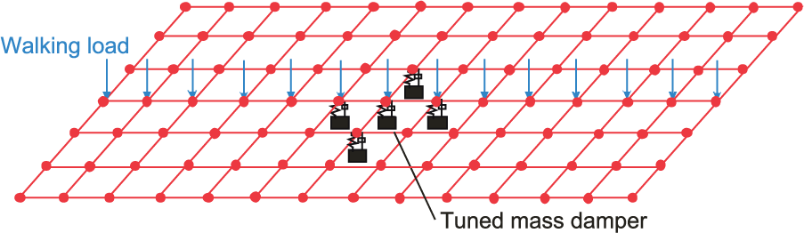
Schematic diagram of the floor–MTMD system.
Combining equations (1) and (2) creates an equation of motion for the coupled system

Partial mode decomposition algorithm
Typically, for each possible set of MTMD parameters, equation (3) is solved in time domain to obtain the floor’s responses. The solution to the set of MTMD parameters that leads to the lowest floor response can be taken as optimal parameters. The calculation for each set of parameters, however, could be very time-consuming when N is very large. Besides, due to the spatial–temporal nature of the walking load, it takes extra time to match walking stride length with finite element mesh size. Unfortunately, the combination of possible sets of MTMD parameters is huge, which means the computational cost for finding optimal values could be unaffordable for long-span floors. Hence, an effective yet accurate algorithmic approach to this problem is necessary.
Since the mass ratio of MTMD with the floor is typically very small (less than 5% in normal cases) and the MTMD plays the role of simply adding structural damping (Lee et al., 2013), we can assume that the installation of MTMD will have negligible effect on the floor’s vibration mode shapes. Furthermore, we assume that only the first p vertical vibration modes, whose modal frequencies are lower than five times the walking frequency, contribute to the floor’s vibrations. With these two assumptions, equation (3) can be transformed into equation (4) using the mode decomposition method

where


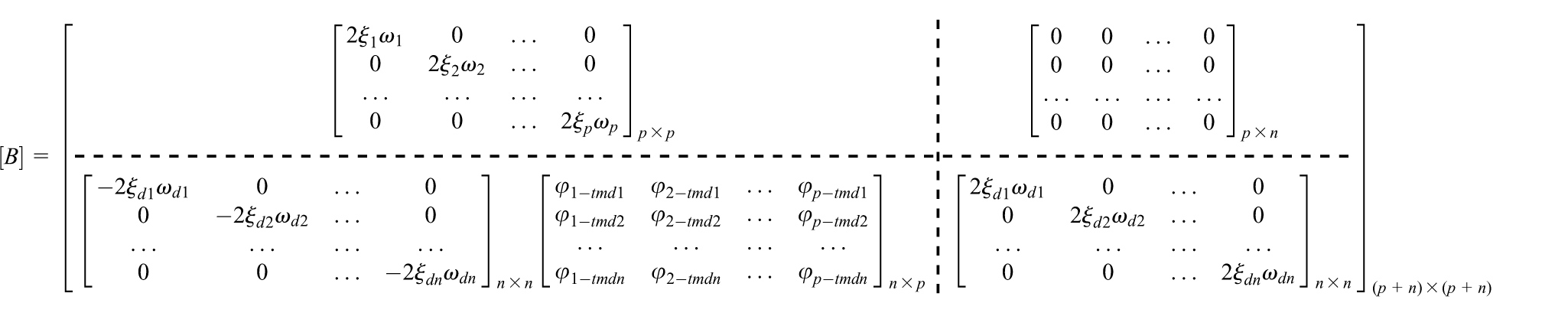
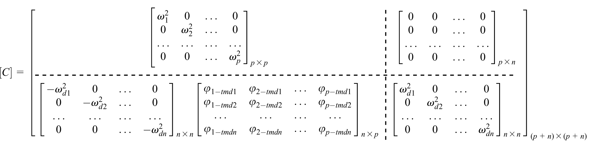

where
Simulation of walking load
A pedestrian’s walking load

where G is the pedestrian’s body weight and
The delta function is introduced here to consider the spatial characteristics of a pedestrian’s moving walking load, and the vertical load is as follows

where
Equation (8) describes the pedestrian’s load along the walking path at any time instant t. When simulating the walking load in a finite element method (FEM) model, the load must be applied on discrete nodes. Thus, the time history of the walking load is truncated into segments which are then assigned to the corresponding nodes along the walking route as sketched in Figure 2. The duration of the load on each node lasts


Simulation of moving walking load in the FEM analysis.
Computational cost of the partial mode decomposition method
Equation (5) is the response calculation algorithm of the hybrid approach presented in this article. Because matrix
Obtain the floor’s former
Simulate the walking load
Calculate the vibration response of the coupled floor–MTMD system by solving equation (5).
By this method, no matter how many TMDs are used and how are they arranged, the response of the floor at any location can be calculated. This calculation scheme benefits from the accuracy of the FEM and also the effectiveness of the mode decomposition method.
A problem and solution that can be applied to the proposed model follows to verify the efficiency and accuracy of the partial mode decomposition method. We suppose that eight people are walking one after another on a floor at the pace rate of 2.0Hz with no pacing phase difference and the distance between two adjacent people is 0.75 m. The walking load model proposed by Bachmann and Ammann (1987) is used to solve this problem. The model includes three orders of DLFs. The DLF value for the first harmonic varies from 0.4 (walking at 2.0 Hz) to 0.5 (walking at 2.4 Hz) with linear interpolation. The second and third DLFs are both equal to 0.1. The pedestrian weight is taken as 80 kg and the walking frequency is 2.0 Hz. The 10-s load history is illustrated in Figure 3. The floor’s acceleration response at its center is calculated by the traditional FEM method via a commercial software and by the partial mode decomposition scheme. The results are compared in Figure 4. Note that the suggested calculation scheme is nearly as accurate as a FEM method. The computation time, however, is significantly reduced from 150.3 s for FEM to 0.84 s for the proposed scheme.
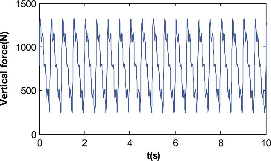
Simulated walking load time history at 2.0 Hz.
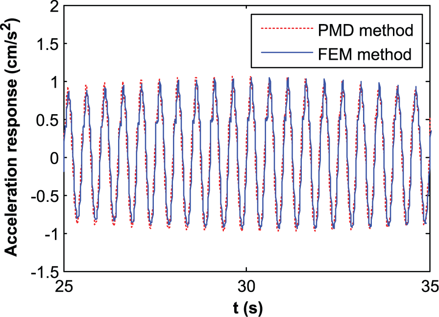
Comparison of computation efficiency.
Parameter optimization using adaptive genetic simulated annealing algorithm
Basic assumptions and optimization function
Equation (5) shows the acceleration response of a given floor where MTMD is affected by many parameters such as location, total mass, number of TMD groups (each group has several identical TMDs), and each group’s parameters (mass, frequency, and damping ratio). In many cases, TMDs are installed where maximum mode displacements are found and therefore, locations of TMDs are typically known. The mass ratio (usually between 1% and 5%) and the number of installation groups can be determined by economic requirements and the available space limitations. Thus, the design parameters to be optimized are the mass, tuning frequency, and damping ratio of each TMD. The natural frequency of the MTMD is often assumed to have a symmetric distribution centered at the floor’s natural frequency. This assumption, however, could jeopardize the effectiveness and stability of MTMD (Kwon and Park, 2004). A more reasonable approach is to adopt asymmetric distribution parameters. Based on all the above assumptions, the parameters’ optimization problem here is to find a suitable pair of variables (

where
Optimization of MTMD parameters using an adaptive genetic simulated annealing algorithm (AGASA)
In recent years, meta-heuristic optimization methods such as the genetic algorithm (GA) (Desu et al., 2006; Hadi and Arfiadi, 1998; Singh et al., 2002), particle swarm optimization (Leung and Zhang, 2009), and harmony search (Bekdaş and Nigdeli, 2011) have been used for estimating optimum parameters of TMDs. In this study, an adaptive GA in conjunction with the simulated annealing algorithm (referred to as AGASA) is utilized for the parameters’ optimization of MTMD. Theoretically, GA has a good ability for global space optimization using genetic operations, but it needs a relatively large population to obtain a satisfactory solution. If GA cannot hold its diversity well before the global optimum is reached, it is liable to be trapped in local optimal solutions. The simulated annealing algorithm SA has the ability to “jump out of” the local optimization and enhance the convergence in the later optimization stage (Wang et al., 2005). Therefore, in AGASA, GA is designed to search for near-optimal solution among the whole solution space, and SA is utilized to search for a better solution by inducing competition between parents and children in the crossover and mutation operations.
Application procedure of the hybrid parameter optimization approach
Figure 5 presents the flow chart of AGASA for MTMD parameter optimization, and the main steps are detailed as follows:
1. Develop finite element model of the target floor and carry out modal analysis to determine the modal frequency, modal mass, and mode shapes of the first p vertical vibration modes which have frequencies five times less than that of the walking frequency (1.6–2.4 Hz).
2. Determine the total mass of MTMD with a preset mass ratio of 1%–5%; then, determine the total number of TMDs and their installation locations.
3. Suppose there are n TMDs to be designed. Randomly generate the mass, frequency, and damping ratio for each TMD. The generated initial populations of

Flow of AGASA.
Figure 6 shows an example of binary code of the genomes and how to calculate their corresponding decoded decimal values. In the optimization process, each TMD’s mass, frequency, and damping ratio are constrained by
4. For the current population of
5. Evaluate the fitness value of each chromosome in the current population. Here, the optimization purpose is to minimize the objective value, which also means the maximum floor acceleration with the current MTMD parameters. The fitness value can be calculated in two stages. First, the objective value for each TMD can be transformed into a first stage fitness value using equation (11)

where objval (i) means the objective value.

Binary code of MTMD parameters and their corresponding decimal values.
To eliminate the early convergence phenomenon and improve selection efficiency, the first stage fitness value is modified using equation (11), which reduces the selection chance of super individuals in the early optimization stage by means of adjusting the fitness values

where
6. Elitist reserve: the best individual of the current population is reserved and brought into the next population. In the selection progress, a new population is reproduced by copying the individuals into the next generation using a Roulette-wheel-selection criterion, which selects individuals with probabilities proportional to their fitness value. In the selection operation, the greater the fitness of an individual, the higher the probability that he or she will be selected for a copy transfer into the next generation.
7. Crossover operation: the parent chromosomes at neighborhood ranks are picked to make exchanges with a crossover probability
8. The mutation operation: a mutation operation with a certain mutation probability
9. The SA improvement of crossover and mutation: after the crossover and mutation operation, the individuals generated are put into competition with their parents using the Metropolis probabilistic acceptance rule as follows

where
10. Repeat the above procedure until present convergence criteria are satisfied. In this study, a maximum integration number is used as convergence criteria.
Application example
To assess the effectiveness of the proposed method and to evaluate the control performance of MTMDs in reducing floor vibration induced by human activities, a long-span concrete floor with the dimension of 90 m × 30 m (Figure 7) is considered. Details of the floor can be found in Lu and Ren (2011).
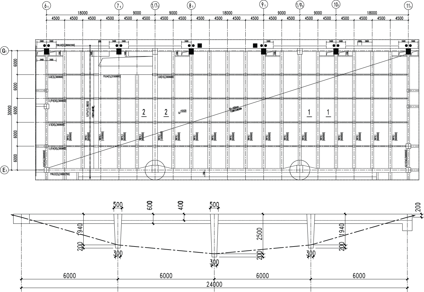
Plan of floor structure.
A finite element model of the floor system was built and validated by comparing with field measurements (Chen et al., 2016). Modal analysis was then carried out on the finite element model to extract the modal frequency, mass, and shape of the first several vertical vibration modes whose frequencies were within five times the walking frequency. The results are shown in Table 1.
Dynamic properties of the floor structure.
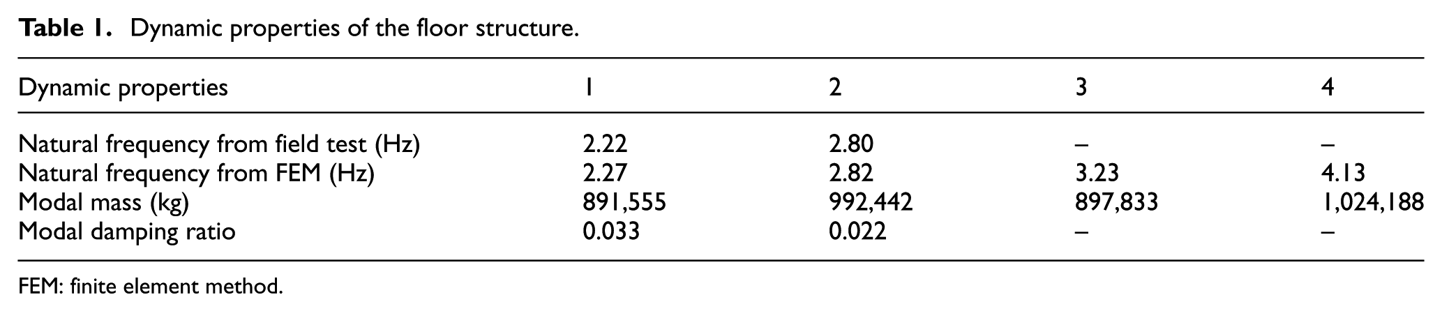
FEM: finite element method.
The first four vertical vibration modes together with the maximum mode value points are illustrated in Figure 8. Note that the floor’s fundamental frequency is lower than 3 Hz, which is the threshold value as specified in the current Chinese design code for concrete structures (CABR, 2010).

The first four modal shapes of the floor: (a) first mode shape, (b) second mode shape, (c) third mode shape, and (d) fourth mode shape.
Optimization of MTMD parameters by the hybrid method
The installation locations of MTMD need to be decided before optimizing its parameters. We call all TMDs with identical parameters and installed in the same region a group, and we represent a group as an equivalent single TMD. The number of groups is essential to an MTMD’s robustness of controlling performance. Too few groups may lead to a lower robustness and too many groups are difficult to implement in practice. We considered three arrangement scenarios for this case: (1) one group at point A; (2) three groups at points B, A, and C; and (3) five groups at points B, D, A, E, and C. For each arrangement, five total mass ratios, µ = 1%, 2%, 3%, 4%, and 5%, were considered. Furthermore, the middle line along the longer side of the floor was chosen as the most unfavorable walking route according to the mode shapes of the first four vertical vibration modes. Having all the above conditions, the hybrid approach was adopted to determine the optimal parameters of the TMD in each group, that is, the mass distribution, tuning frequency, and damping ratio. In the calculation, an initial population consisting of 40 random chromosomes (each had 15 genes) was generated in AGASA. The resulting optimal parameters for three group arrangements are summarized in Table 2. The walking load model proposed by Bachmann and Ammann (1987) was used in the optimization.
Variations in optimum parameters of TMD with mass ratio and the number of TMDs.
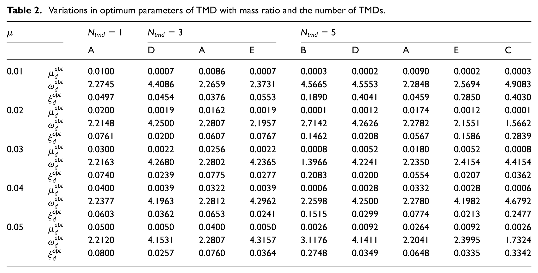
Figure 9(a) to (c) illustrates the variation in floor peak accelerations with walking frequency and total mass ratios for the three arrangements, respectively. Figure 9(a) shows that for Arrangement I, the floor’s responses are significantly reduced at its fundamental frequency of 2.2 Hz; hence, the higher the total mass ratio, the lower the peak acceleration. However, when the walking frequency is about 2.05 Hz (almost half that of the floor’s fourth modal frequency, which is 4.13 Hz), the floor’s peak acceleration does not decrease much with the increase in total mass ratio ascending from 1% to 5%. Clearly, more groups are needed to reduce the higher mode’s vibration and to improve the overall MTMD performance. For arrangement II (Figure 9(b)), we can see that when masses are added to location D and E where the maximum displacement of the fourth mode takes place, vibrations of the fourth mode can be efficiently controlled. Taking the results in Table 2 for total mass ratio µ = 1%, as an example, a better performance of the designed MTMD can be achieved by putting a TMD with 0.07% mass at points D and E.
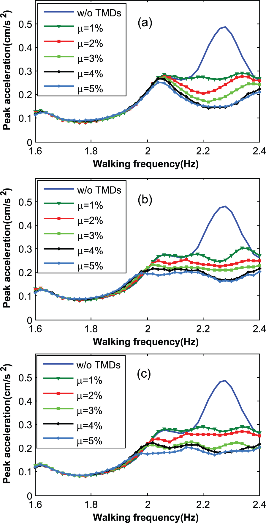
Maximum acceleration of the floor with/without MTMDs: (a) one TMD is at point A, (b) three TMDs are at points D, A, and E, and (c) five TMDs are at points B, D, A, E, and C.

Optimization curves for different mass ratios of TMD located at point A.
Parametric analysis on the robustness of designed MTMD system
This section investigates the robustness of the designed MTMD system to situations as different walking load models, varied dynamic properties of the floor, and detuning of MTMD parameters. High computational efficiency of the proposed hybrid approach makes extensive parametric studies possible.
Different walking load models
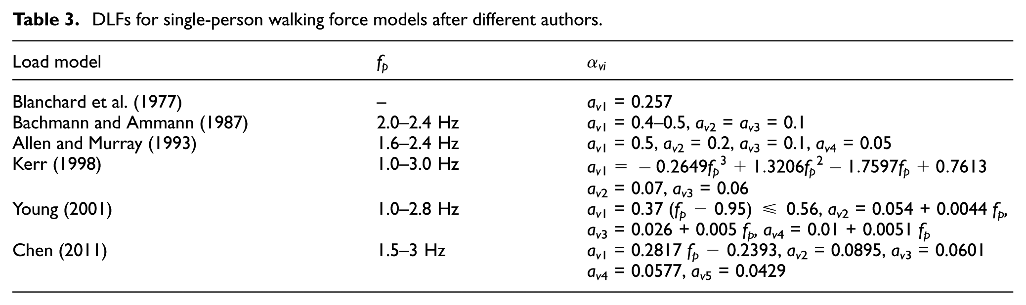
Since the late 1970s, several walking load models have been proposed by researchers and adopted by various design guidelines. These models are different from each other in terms of the number of harmonics, the dynamic load factor, and phase angle of each harmonic. It is, therefore, necessary to evaluate the performance of an MTMD system, which is designed using one specific walking load model under different walking load models. This issue is often misunderstood and in need of clarification. To this end, the MTMD designed a previous section for Ntmd = 1, 3, 5, and a total mass ratio µ = 0.03 is taken as an example. Five new walking load models were selected, which were suggested by Blanchard et al. (1977), Allen and Murray (1993), Kerr (1998), Young (2001), and Chen (2011). Table 3 presents a detailed description of the step frequency values and DLFs to be employed in the mathematical representation of the six load models. The peak accelerations of the coupled floor–MTMD system to the five-load models were calculated and compared with those from Bachmann and Ammann (1987) in Figure 11.
DLFs for single-person walking force models after different authors.

Maximum acceleration of the floor with/without MTMDs under (a) Blanchard et al. (1977), (b) Bachmann and Ammann (1988), (c) Allen and Murray (1993), (d) Kerr (1998), (e) Young (2001), and (f) Chen (2011) testing walking load model when µ = 0.03.
Figure 11 indicates that different walking load models lead to different MTMD performances. When the second-order term of the walking load was ignored as shown in Figure 11(a) or the second-order term of the walking load was not properly valued as shown in Figure 11(d) and (e), the floor’s vibration was dominated by the first mode. Consequently, it is effective to concentrate all masses of TMDs at point A, that is, Arrangement I. However, when the second-order term of the walking load was properly included as in Figure 11(b), (c), and (f), a multi-mode could be excited under the walking load. Therefore, Arrangement II or III becomes a better choice. From the viewpoint of practice, a walking load model with a higher order of harmonics is recommended for designing MTMD parameters.
Varying frequency and damping ratio of the floor
It should be noted that structural design parameters, for example, the modal mass and the natural frequencies, might change during the lifetime (Werkle et al., 2013). These parameters might change for various reasons, such as the removal of a partition wall, decoration, and usage function change, which results in the change in natural frequencies. Moreover, Allen et al. (1985) stated that an increase in the damping of a structure could occur due to human–structure interaction, and consequently, a higher damping ratio was recommended for calculating the vibration induced by crowd loading. Taking the designed MTMD for µ = 0.03 and Ntmd = 1, 3, 5, for example, the influence of the variations in the floor’s dynamic properties on the effectiveness of MTMD was investigated. To this end, a response reduction coefficient R as defined in equation (14) is utilized to quantify the efficiency of MTMD; hence, the larger the value R, the better the performance of MTMD

Suppose the floor’s fundamental frequency and damping ratio vary by ±10% and ±50%, respectively. The calculated coefficient R is shown in Figure 12 for three arrangements. By comparing Figure 12(a) to (c), it can be seen that with the increase in the TMD number, the performance of optimally tuned MTMD system is improved. This indicates that the optimization procedure can find a reasonable arrangement of the mass distribution of MTMD. However, this may be not true for the robustness of MTMD when the structural parameters are changed (e.g. for Δω = −10%, R = 0.3 for the one-TMD system in Figure 12(a) and R = 0.17 for the three-TMD system in Figure 12(b)). Also, it is worth noting that the change in the structural parameters may even increase the performance of MTMD. The influence of the structure parameters on MTMD performance is complicated, especially for the structures with dense frequencies. We can also see that the effectiveness of the TMDs is sensitive to the structure’s natural frequencies. In Figure 12(b), it is found that the control performance gradually increased with the decrease in structure’s damping. The reduction coefficient R decreased from 51.78% to 15.59% and 25.32%, respectively, when the structural frequency is decreased 10% or increased 10%.
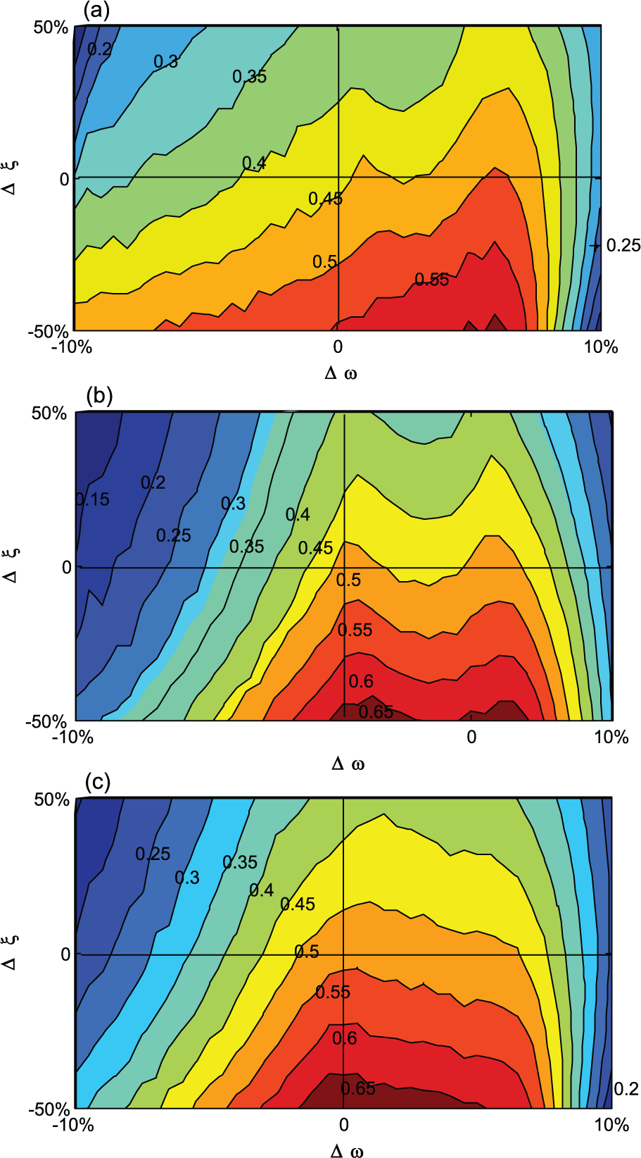
Effect of structure parameters’ change on response reduction coefficients where µ = 0.03′, thus (a) Ntmd = 1, (b) Ntmd = 3, and (c) Ntmd = 5.
Detuning of MTMD’s natural frequency and damping ratio
Similarly, the variation in MTMD’s frequency and damping ratio can also affect the performance of MTMD. The calculated response reduction coefficient with a ±10% deviation of the MTMD’s frequency and ±50% damping ratio is shown in Figure 13. It can be seen that the proposed optimization approach has a good performance in finding the optimal parameters of MTMD. From Figure 13(a) to (c), for the same total mass of MTMD, the sensitivity of the effectiveness of the MTMD to the change in MTMD’s natural frequencies and damping decreases as the number of TMDs increases. The proposed design method of MTMD that considers mass distribution among TMDs has a good vibration control performance and is robust.
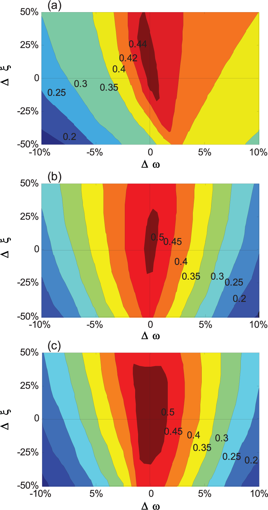
Effect of MTMD’s frequency and damping on response reduction coefficients where µ = 0.03, thus (a) Ntmd = 1, (b) Ntmd = 3, and (c) Ntmd = 5.
Conclusion
Installation of MTMDs has proved to be an effective and practical way to reduce long-span floors’ responses due to occupant walking. Optimal design parameters for the MTMD are critical for its overall performance. Most previous optimization methods, however, are either based on one vibration mode assumption or are very time-consuming. To overcome these problems, this article suggests a hybrid approach for parameter optimization of MTMD for reducing floor vibrations. The proposed approach uses a partial mode decomposition algorithm to calculate the dynamic responses of coupled floor and MTMD system. The algorithm has proven to be computationally efficient in time saved and is more accurate than the FEM-based method. The proposed approach also adopts the adaptive genetic simulated annealing algorithm for parameter optimization. This article presents in detail the application of the hybrid approach to MTMD parameter optimization for a long-span floor. The resulting MTMD system is found effective in reducing floor vibration and is robust under various conditions. Finally, parametric investigations indicate that different walking load models and uncertainties in the dynamic properties (frequency and damping ratios) of floors and TMDs need to be considered when designing an MTMD system. Experimental validation of the suggested hybrid approach will be the next step of the research work.
Footnotes
Declaration of Conflicting Interests
The author(s) declared no potential conflicts of interest with respect to the research, authorship, and/or publication of this article.
Funding
The author(s) disclosed receipt of the following financial support for the research, authorship, and/or publication of this article: This study was financially supported by the National Science Foundation of China (NSFC, no. 51478346) and State Key Laboratory for Disaster Reduction of Civil Engineering (SLDRCE14-B-16).