
Abstract
Geiger domes are composed of cable and strut elements. This property of cable domes is the same as tensegrity structures, but in contraction to tensegrity structures, strut elements do not have a function that balances tension in cable elements with compression. In this study, a new cable dome configuration, that mimics the form of tensegrities, is proposed which is able to spread effect of an applied load into all elements of the dome and reduces its local impact. Form-finding and analysis of the Geiger and new dome configurations are performed based on the principle of minimum potential energy. Self-equilibrium forms with minimum potential energy are determined using genetic algorithms. The ability of genetic algorithm based potential energy minimization approach to perform form-finding of loaded or load free cable domes is investigated. Performance of the proposed configuration is tested and compared with the Geiger configuration under various loading conditions.
Introduction
The idea of tensile integrity structures dates back to the beginning of 20th century (Fuller, 1962). After this invention, Snelson (1965) practised new configurations as continuous tension and discontinuous compression structures. The first non-regular tensegrity structure was invented by Buckminster (1975) and further studies were focused on form-finding of tensegrity structures (Tibert and Pellegrino, 2003). Different methods for the design of tensegrity structures were developed such as dynamic relaxation (Belkacem, 1987; Day and Bunce, 1969; Motro and Nooshin, 1984), force density (Linkwitz, 1999; Linkwitz and Schek, 1971; Schek, 1974) and reduced coordinates (Sultan et al., 1999). Computational methods were also developed by various authors (Chen and Feng, 2012; Estrada et al., 2006; Li et al., 2010; Masic et al., 2005; Pagitz and Tur, 2009; Zhang et al., 2006; Zhang and Ohsaki, 2006) for the design of complex tensegrity structures.
Connelly used and developed energy methods (Connelly, 1982, 1993; Connelly and Back, 1998; Connelly and Terrell, 1995). These studies showed that energy methods can be used to perform form-finding of tensegrity structures. Pellegrino (1986) proposed nonlinear programming method that performs form-finding of tensegrity structures using a constrained energy minimization approach. Achievements in computation power supported that process and search methods have been developed for the design of tensegrity structures (Li et al., 2010). Paul et al. (2005) introduced evolutionary algorithms for the determination of tensegrity structures with non-regular forms. Xu and Luo (2010a, 2010b) converted the form-finding problem of non-regular tensegrity structures into a constrained optimization problem and also developed a simulated annealing algorithm to perform pre-stress optimization and form-finding. Koohestani (2012) proposed a genetic algorithm form-finding method based on minimization of eigenvalues of the force density matrix and developed analytical and numerical form-finding methods (Koohestani and Guest, 2013). Faroughi et al. (2014) used a genetic algorithm based on the rank deficiencies on the geometry, the pre-stress coefficients and the semi-positive definite condition of the stiffness matrix. Ant colony systems were used by Chen et al. (2012a) to perform form-finding of tensegrity structures. A node-based method was developed by Gan et al. (2015). Lee and Lee (2014, 2016) used frequency constraints for optimum self-stress design of cable–strut structures and developed a method for topology design of tensegrity structures. Another study based on optimization of force density is performed by Cai and Feng (2015). Ohsaki and Zhang (2015) used a nonlinear programming approach to investigate the stability of the self-equilibrium shape. Studies show that different numerical methods were developed to determine the self-equilibrium state of tensegrity structures. Metaheuristic techniques and energy methods were used for the purpose of form-finding of tensegrity structures; however, minimization of total potential energy (TPE) have never done using metaheuristic techniques in order to perform form-finding of cable domes.
Dome design of Geiger is composed of nested circular structures that contain vertical strut elements connected to cable elements. Various configurations of this design were studied. Pellegrino (1992) investigated the structural behaviour of pre-stressed cable domes under different loading conditions. Kawaguchi et al. (1999) investigated optimum shape to gain maximum stiffness in a full-scale elliptic cable dome. Yuan and Dong (2002) performed nonlinear analysis of cable dome structures. Lazzari et al. (2003) developed a finite element code for geometrically nonlinear analysis. Yuan and Dong (2003) presented a specific equilibrium state of integrally feasible pre-stressed cable domes. Fu (2005) analysed cable domes using a numerical method. A numerical method is also presented for form-finding of cable–strut structures and applied to domes by Tran and Lee (2010). Tran et al. (2012) proposed a numerical method for the initial pre-stress design of cable dome structures with multiple independent pre-stressed modes.
Stability of pre-stressed structures was investigated using different computational methods (Chen et al., 2012b, 2015; Guest, 2010; Sultan, 2013). The use of evolutionary algorithms and principle of minimum potential energy on form-finding (Uzun, 2016) and analysis (Toklu and Uzun, 2016) of tensegrity structures was previously investigated and the proposed method provided accurate solutions based on the relation between stability and potential energy. Energy method is successfully applied to form-finding of free-form tensegrities and analysis of well-known tensegrity structures. This study is an application of the previously proposed method for the development of a new tensegrity dome configuration that meets evolutionary algorithms with the principle of minimum potential energy for the first time in order to determine the stable form of cable domes.
This study aims to develop a new cable dome design and apply principle of minimum potential energy on form-finding and analysis of this structure. The inner ring of Geiger domes is composed of cable elements supported with horizontal strut elements. In spite of using horizontal strut elements, the configuration of this form is changed in a way to create a tensegrity structure. Same elements are used and it is aimed to gain the most important advantage of tensegrities, distribution of the effect of applied load to all elements rather than having a local effect with high impact, to cable domes. Form-finding and analysis of the Geiger and new dome configurations are performed using the same parameters. The performance of the new dome configuration is compared with that of the Geiger dome configuration. Self-equilibrium forms are determined in a way to satisfy fair conditions for both structures and analyses are performed at various loading conditions. Self-equilibrium states are determined using only the basic information about cable domes which are nodal joints and element properties. All solutions are performed using a computer with Intel Core i7-3610 CPU that works at a maximum clock speed of 3.3 GHz.
Form-finding of tensegrity domes
Ziegler (1968) stated that equilibrium configuration of a conservative system is stable when the potential energy of the system demonstrates a minimum. This principle can be used in a way to determine the equilibrium configuration of a structure (Timoshenko and Gere, 1961) based on the fact that the stability of structures is inversely proportional to potential energy (Alfutov et al., 2013; Gambhir, 2004; Godoy, 1999). The development of metaheuristic algorithms enabled application of the minimum energy principle to civil engineering problems, without requirement of differentiation of energy function or incremental techniques, by carrying a search to find the stable form with minimum potential energy. In this study, self-equilibrium form of tensegrity domes, with or without load, are determined by minimization of TPE using genetic algorithms. Starting from a random structural form, genetic algorithm increases the stability of the structure by decreasing the TPE.
The form-finding process of tensegrity domes, under load or without any external load, is performed based on a set of assumptions (Feng and Guo, 2015; Ohsaki and Zhang, 2015). Elements of the structure are assumed to be straight, self-weight of the structure is neglected, element failure related to yielding and buckling is not considered and no external loads are acted on the system. The process requires simple information about elements of the structure which are element type (cable or strut), nodal joints, material properties (modulus of elasticity), stress-free element lengths and cross-sectional area of elements.
Tensegrity dome configurations
Tensegrity structures are composed of cable and strut elements. In this study, single units are used to construct Geiger and new dome configurations. Both configuration types are composed of one strut and four cable elements. Two cables have the function of supporting units that hold the inner ring and the other two cables are used to construct the inner ring of the dome.
The main difference between the two configurations is the connection of elements. As illustrated in Figure 1, Geiger configuration has two cable elements connected to each end of strut element while new configuration has one and three cable elements connected to conjugate ends of the strut element. Both of the units have five nodal joints and they are denoted as a, b, c, d and e.

Single units used to construct Geiger and new configurations.
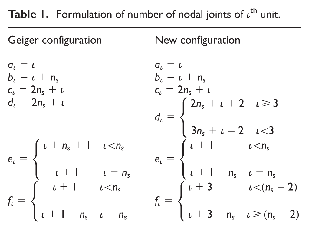
Nodal connections in a configuration are numbered according to the formulation given in Table 1. In these equations,
Formulation of number of nodal joints of ιth unit.
Genetic algorithm for TPE minimization
TPE minimization is performed in order to determine the Self-equilibrium form of tensegrity domes, under load or without load, using evolution process of the genetic algorithm. For this purpose, the basic and well-known steps of the simple genetic algorithm are used. Principles of this process can be found in the study of Uzun (2016) where form-finding of free-form tensegrity structures was performed using the principle of minimum potential energy. Difference in this study is modifying the fitness function by adding work done by applied forces. Flowchart of this process is adapted from the study of Toklu and Uzun (2016) and given in Figure 2.
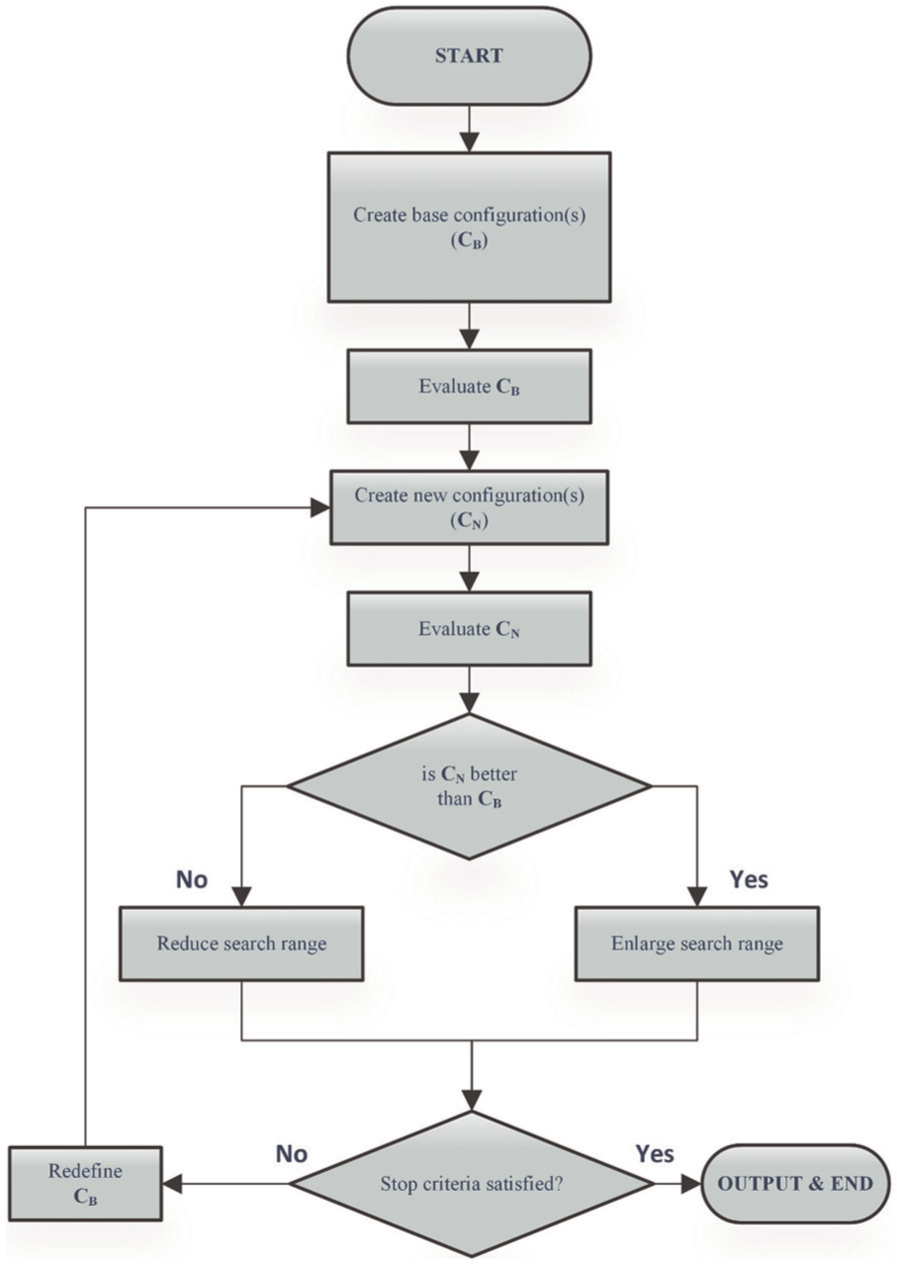
General procedure for TPE optimization using metaheuristic optimization techniques (Toklu and Uzun, 2016).
Parameters of the evolution process are determined according to the results of the study of Grefenstette (1986). Genetic algorithm operators, elitism, selection, crossover and mutation, are applied to base configurations, after evaluation of the fitness, during the creation of new configurations. A dynamic mutation range with a convergence limit is used. The process ends when the convergence limit is reached.
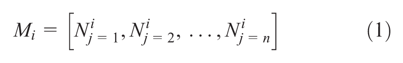
Genetic algorithm process finds the optimum solution using a set of solutions called population of members. Each member corresponds to a solution which determines coordinates of nodal joints of tensegrity dome. Nodal joints of chromosome of a member are represented as genes. ith member of the population
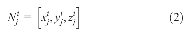
In all, 10% of fittest members in the population are determined to be elite members. The selection process of mating members is performed using pie graph selection method. The number of selected members is determined to be 90% of all members. After the selection process, a one-point crossover is performed at each mate with a probability of 0.95. Non-elite child members are mutated according to a predetermined mutation rate. Mutation probability of this process is determined to be 0.04. A gene is mutated by changing axial coordinates (
Parameters of TPE minimization process.
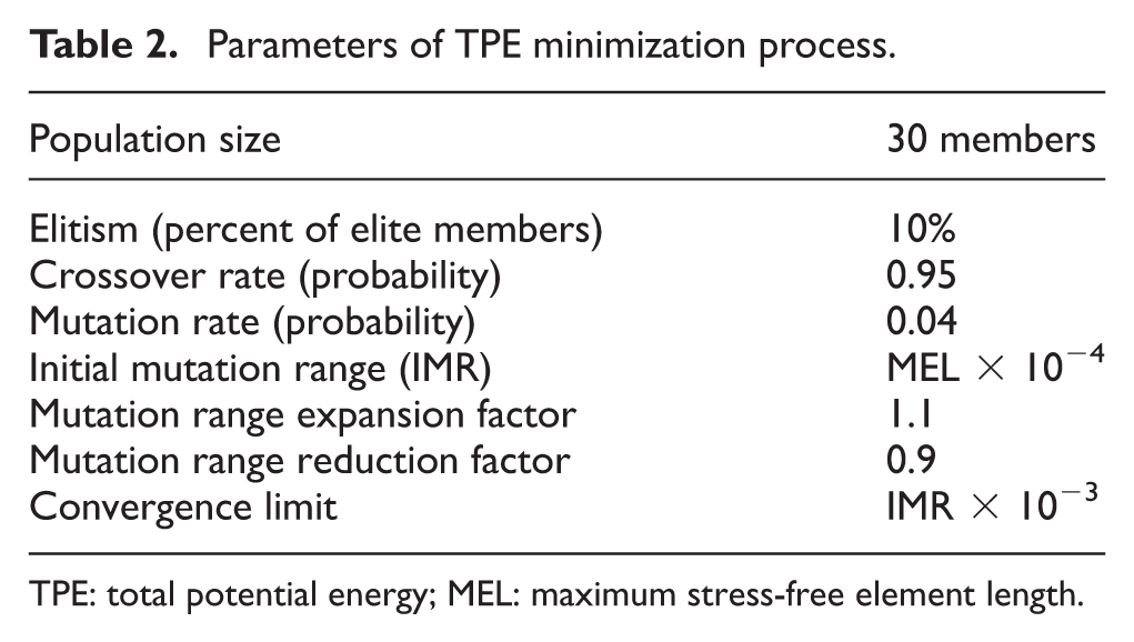
TPE: total potential energy; MEL: maximum stress-free element length.
Fitness function
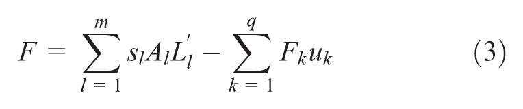
Fitness function of a cable–strut structure is the sum of strain energy densities of all cable and strut elements. In the case of application of external loads on the structure, work done by these loads is also added. The sum of potential energies of m number of elements and applied loads are calculated using equation (3) where s is the strain energy density, A is the cross-sectional area,

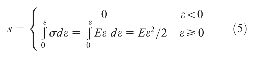
Strain energy density of an element is calculated using equation (5) where
The strain of an element is defined in equation (6) where


Form-finding of tensegrity domes with eight units
Form-finding of eight-strut tensegrity domes with Geiger and new dome configurations are performed separately after determination of nodal joints using equations given in Table 1. Initial element lengths of both designs are identical. The length of struts, hoop cables and support cables at rest are 100, 50 and 150 mm, respectively. Structural properties of Geiger and new dome configurations are given in Tables 3 and 4. The cross-sectional area of cable and strut elements are 10 and 100 mm2, respectively. Modulus of elasticity of cables and struts are independently determined to be 110 and 210 GPa.
Properties of the cable dome with Geiger configuration after form-finding process.
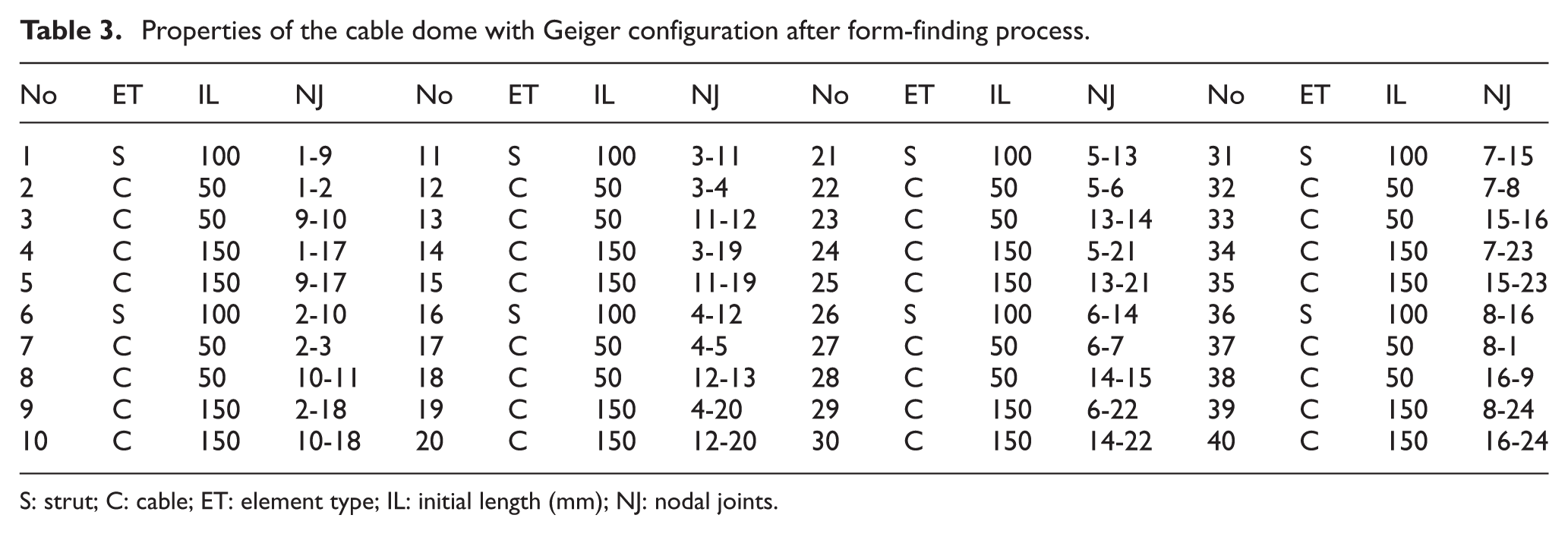
S: strut; C: cable; ET: element type; IL: initial length (mm); NJ: nodal joints.
Properties of the cable dome with new configuration after form-finding process.
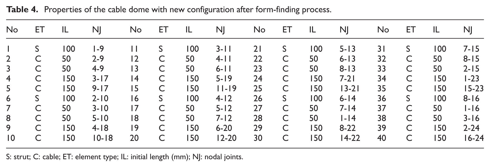
S: strut; C: cable; ET: element type; IL: initial length (mm); NJ: nodal joints.
Tensegrity structures have a Self-equilibrium form where the tension in cable elements is balanced with compression in strut elements. TPE is a measure of strain energy within elements of a structure. Based on this background information, it is aimed to have dome structures with minimum positive TPE that sustain a balance between tension and compression elements.
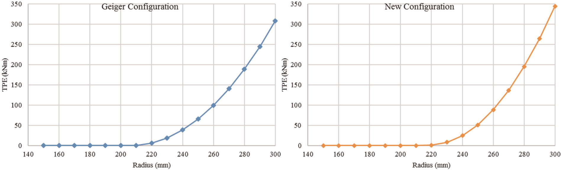
The radius of the outer ring, where support cables are connected, is another structural property of tensegrity domes that affects strain density of elements. The increase in radius raises strain density while lowering the radius causes formation of strain-free unstable shape. In order to determine the tensegrity form that provides minimum required strain density within elements, the radius of tensegrity domes is investigated in terms of TPE.
Results of radius investigation of Geiger and new dome configurations are illustrated in Figure 3. It can be clearly seen that the increase in radius causes accumulation of strain energy density in the elements. TPE increases in both the configurations as a result of the increase in dome radius. TPE of Geiger configuration exceeds 307,838,929.440 N mm when the radius is determined to be 300 mm. The new configuration has 344,507,669.993 N mm TPE at this radius. It can be stated that new configuration has a wider span with higher radius when both the configurations are set to the same magnitude of TPE. This is the first advantage of new configuration over the Geiger configuration.
Effect of outer radius on TPE.
It is aimed to set the radius of both configurations to a value that will provide positive TPE with minimum strain energy density within the elements. Investigations showed that TPE of Geiger configuration is minimum between radius values of 210 and 220 mm. Fine tuning within this section provided TPE of 10.094 N mm when the radius is 214.120 mm. After a series of similar tests, the new configuration with 206.767 mm radius is found to have 10.687 N mm TPE. Storing similar magnitude of potential energy in self-equilibrium form of both dome configurations satisfies fair condition while testing both structures. For this purpose, TPE is taken as a measure because it is also an average measure of level of initial pre-stress/strain in the members.
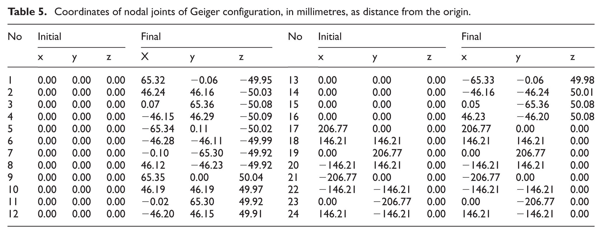
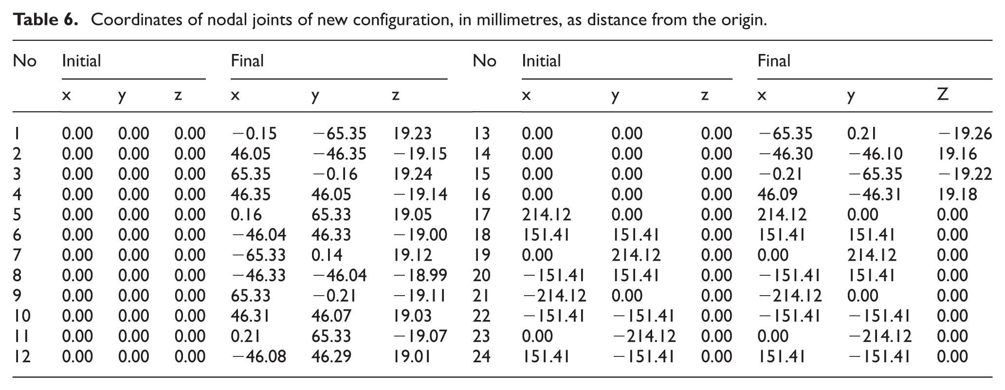
Among the configurations with similar TPE, new configuration has a wider span. The shape of self-equilibrium forms of both configurations is illustrated in Figure 4. Nodal connections and element types are given in these illustrations. Coordinates of nodal connections are listed in Tables 5 and 6. The thickness of inner ring seems to be lowered with the new configuration which has a thickness of about 40 mm. The thickness of Geiger configuration is analogous to the length of horizontal strut members which is about to be 100 mm.
Self-equilibrium form of dome structures with Geiger and new configurations.
Coordinates of nodal joints of Geiger configuration, in millimetres, as distance from the origin.
Coordinates of nodal joints of new configuration, in millimetres, as distance from the origin.
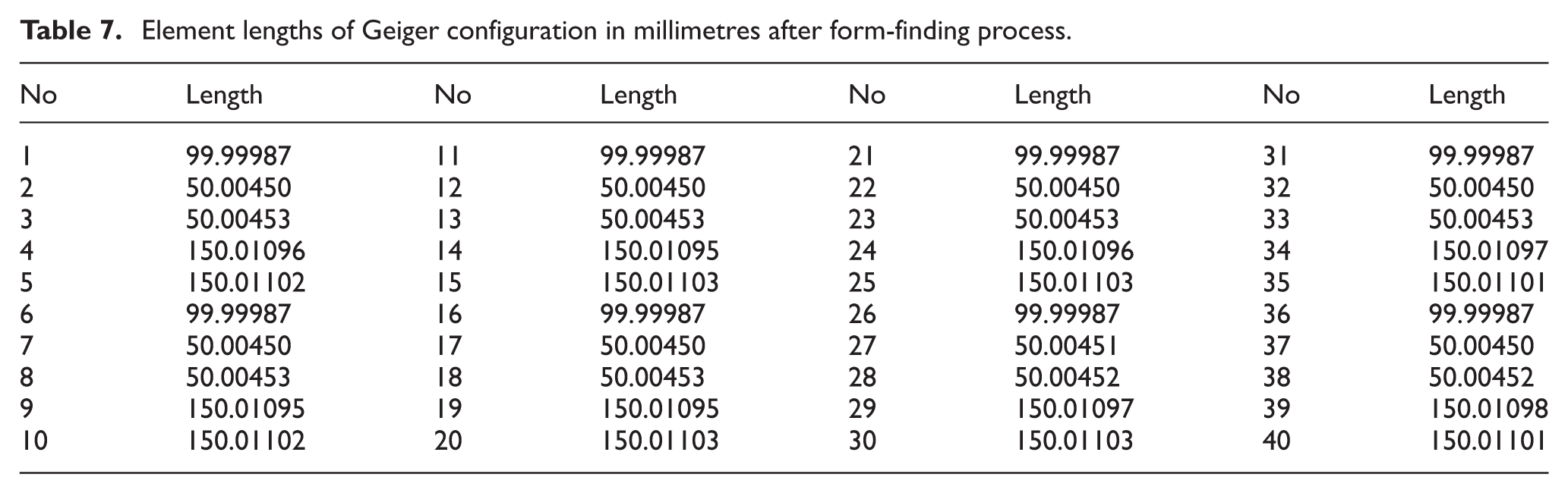
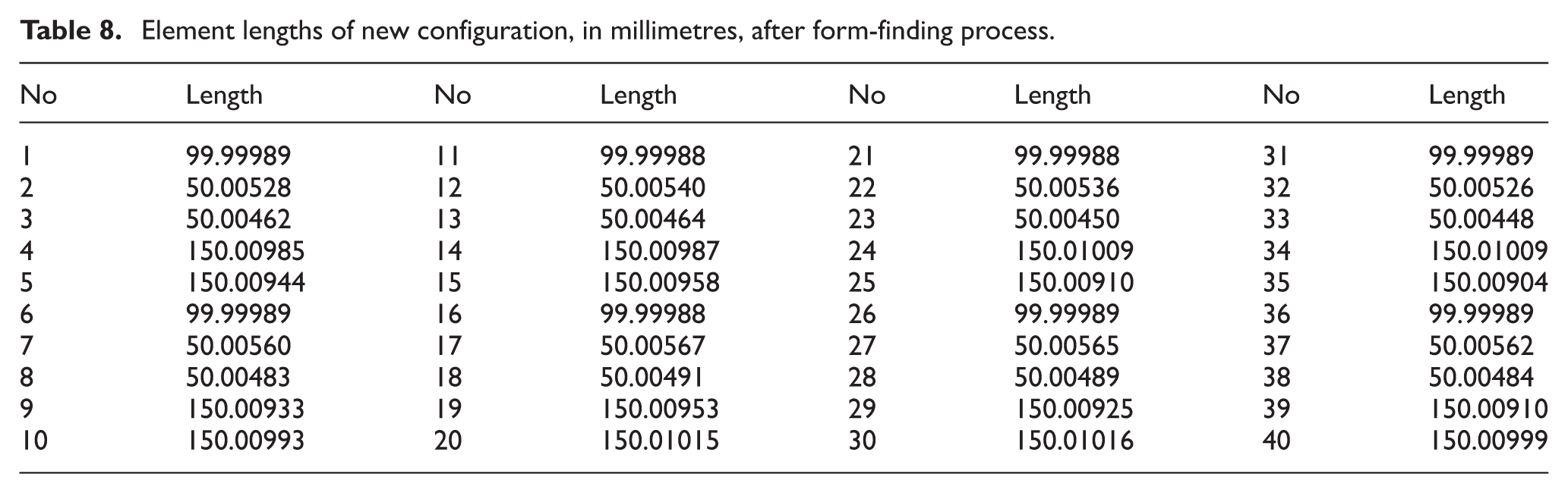
Element lengths of the self-equilibrium form of both configurations are given in Tables 7 and 8. Results show that all cable elements are in tension and all strut elements are in the compression state. Joint coordinates and element lengths of the self-equilibrium form of both configurations are assigned as initial conditions on further analyses.
Element lengths of Geiger configuration in millimetres after form-finding process.
Element lengths of new configuration, in millimetres, after form-finding process.
Analysis of tensegrity domes with eight units
Self-equilibrium form of tensegrity domes is analysed at varying loading conditions. In order to accomplish this, TPE minimization is performed at each loading condition. Deformations and nodal displacements are determined after loads are applied. Structures are loaded from a single nodal joint of each configuration as illustrated in Figure 5. Loads are varied from −500 to 500 N parallel to the z-axis. Same loads are applied to both dome configurations.

Illustration of the loads and the joint configuration (dashed lines do not represent elements).
TPE variation related to applied load is given in Figure 6. Results show that TPE decreases with increasing magnitude of the negative and positive loads. As it is stated before, TPE is a measure of strain energy, but in this case, it also includes the effect of applied load. Deformations directly affect the magnitude of TPE. It can be stated that TPE can be seen as a measure of deformations and displacements occurred in the dome structures. Applied load has a negative effect on TPE, and its effect is much more than strain energy density. In the case of structures with identical elements, the same number of cable and strut elements with same cross-sectional area and strength, the lower magnitude of TPE means higher nodal displacement and element deformation.

TPE variation related to the applied load to the domes with Geiger and new configurations.
Results show that TPE of the dome with Geiger configuration is lower at each loading condition. This means that deformations and nodal displacements are lower in the new configuration. The difference in magnitude of TPE increases with increase in the magnitude of the load. This is the second result of this study, which proposes another advantage of the new configuration. In order to prove that outcome, axial displacements of the load applied joints are investigated separately as illustrated in Figure 7.
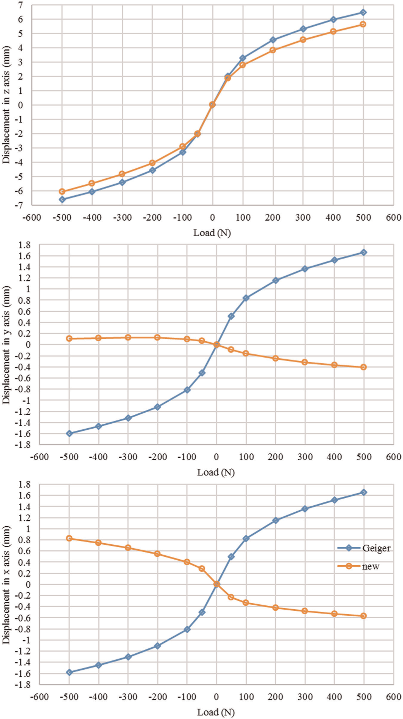
Axial displacements of load applied node of Geiger and new dome configurations.
Deformation of the load applied node of the Geiger configuration is higher than the new configuration. Positive loads cause displacement in the positive direction of z-axis while the reverse is observed with negative loads. The magnitude of displacements in z-axis increases with increasing magnitude of the load and the difference of displacement between two configurations also increases with increasing magnitude of the load. Displacement in x-axis and y-axis is much lower in the new configuration when compared to the Geiger configuration and they are in opposite directions. Negative loads cause displacement in the positive direction of the axes in new configuration while the direction of load and displacement are identical in Geiger configuration. All in all, results show that displacements along the coordinate axes in the new configuration are lower than that occurred in Geiger configuration.
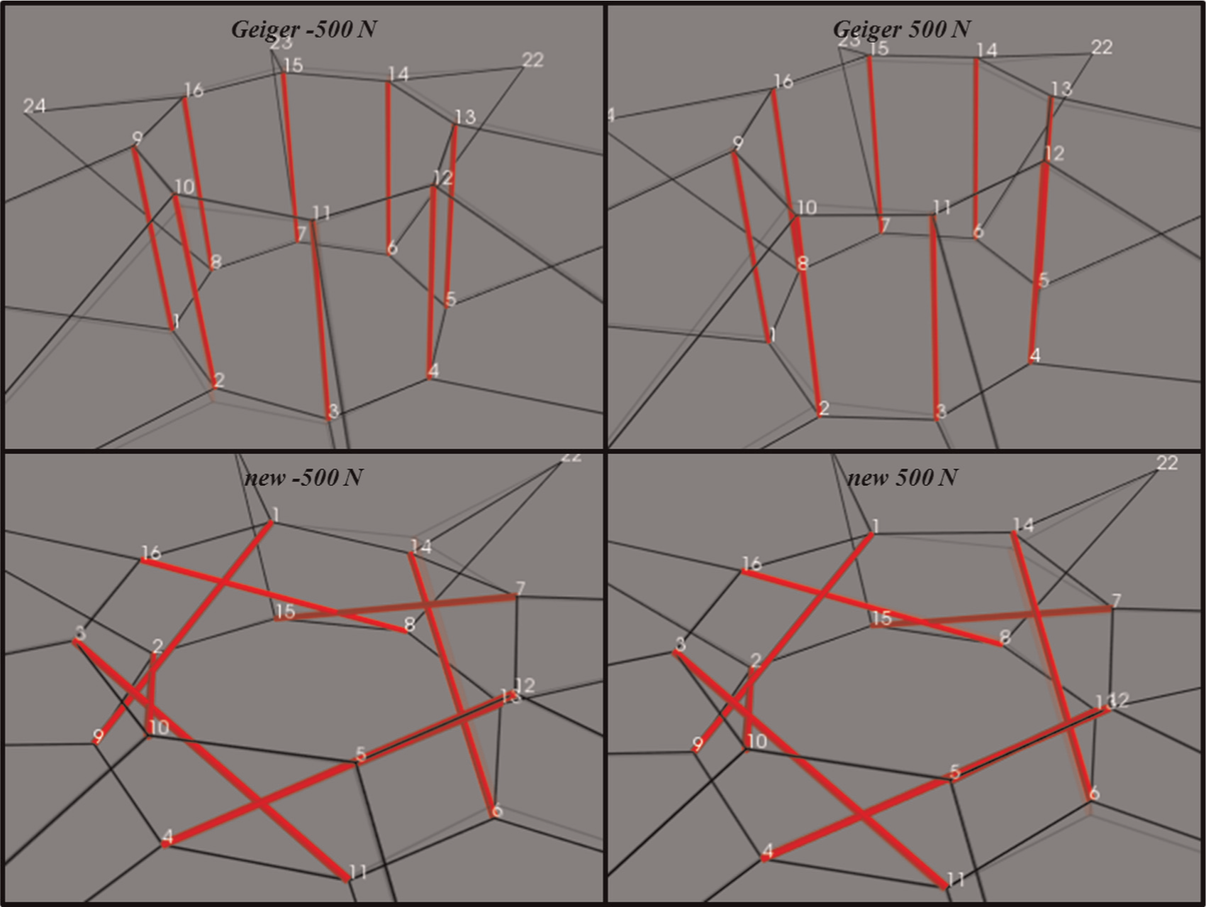
Displacement of nodal joints is illustrated in Figure 8 for both Geiger and new configurations. These illustrations are results of loading at −500 and 500 N. Displacements are visualized using the pale image of the initial condition of structures before the application of loads. Changes in the elements around the load applied nodes can be observed, but displacements at other nodes are hard to comprehend so that nodal displacements of all joints are listed in Tables 9 and 10.

Illustration of deformations in the Geiger and new dome configurations (pale lines represent initial form).
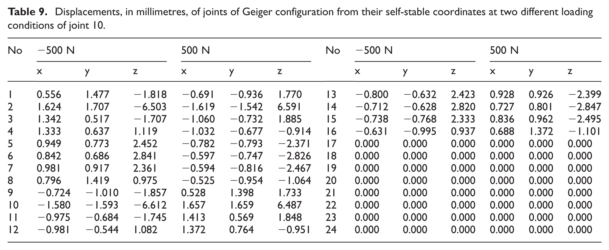
Displacements, in millimetres, of joints of Geiger configuration from their self-stable coordinates at two different loading conditions of joint 10.
Displacements, in millimetres, of joints of new configuration from their self-stable coordinates at two different loading conditions of joint 14.
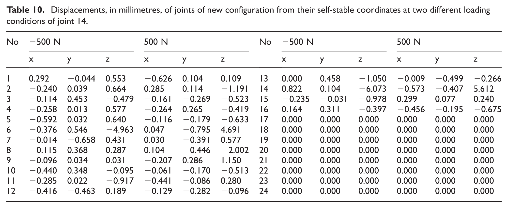
Results show that opposite end of loaded strut element has the next higher magnitude of axial displacements in both configurations. Nodal displacements are identical in Geiger configuration. The new configuration also has a high axial displacement at opposite end of loaded strut element, but the magnitude of displacement is lower than the loaded end. This is caused by the natural property of tensegrity structures. The effect of applied load is distributed in all other elements, and a local effect of applied load is prevented. This property of tensegrities is also the result of the low magnitude of displacement in load applied joints.
Linear displacement of nodal joints after the application of loads is given in Table 11. The load applied to 10th joint of Geiger configuration caused highest deformations at the joints 10 and 2. Second joint is connected to the same strut element with 10th one. Deformations are similar at both loading conditions in Geiger configuration. Lowest deformation is observed at joint 16 when the applied load is −500 N.
Linear displacement of nodal joints.
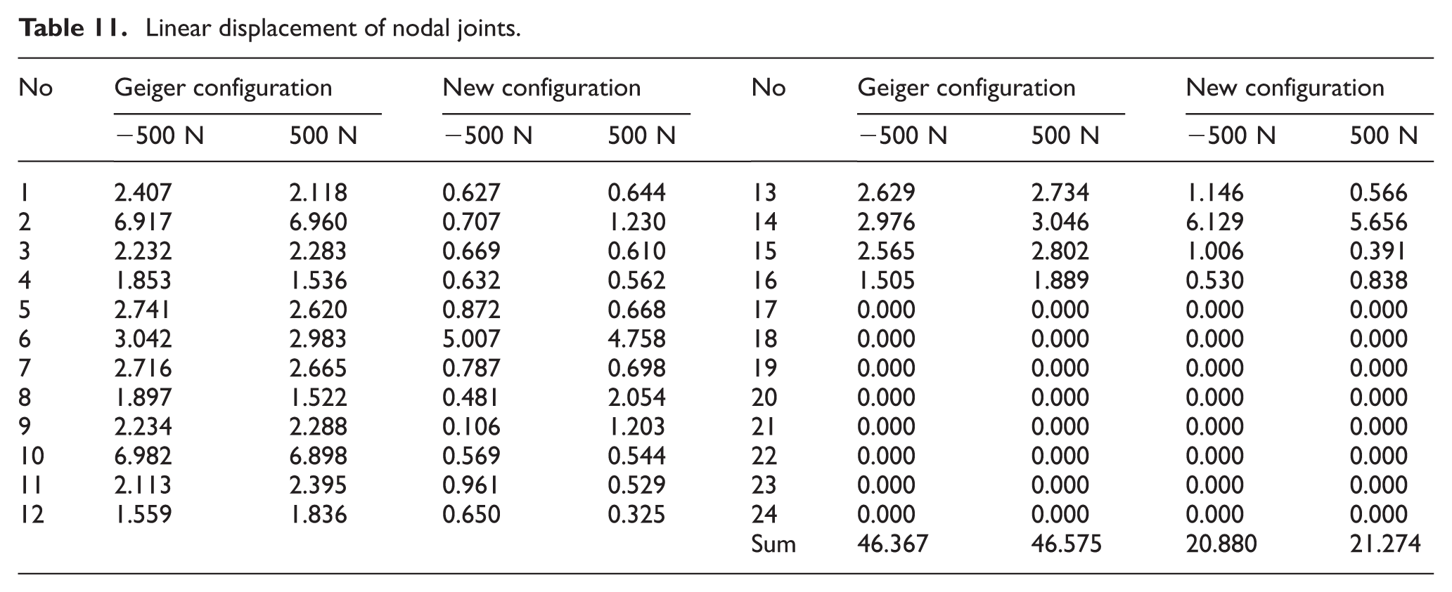
Linear displacement of joints of the new configuration is highest in the load applied joint and its counter at the same strut element. The maximum displacement is lower than the one in the same class with Geiger configuration. Lowest deformation is observed at joint 12 when the applied load is 500 N.
In order to get an estimation about the overall displacement of joints, the sum of displacements in all four cases is also provided. The sum of displacements shows that total displacement of the new configuration is less than half of the total deformations of Geiger configuration. This is another advantage of the new configuration when compared to the Geiger configuration.
Previously, it is stated that new configuration distributes an applied load to the whole of the structure. Results show that this does not occur as the arithmetic allocation of the impact of the applied load to other elements. This new design uses strength and resistance of other elements in order to lower the effects of the applied load. The impact of the applied load is reduced by the resistance of all elements. As a result of this, magnitude of deformations of elements and nodal displacements at joints are much lower in the new configuration when compared to the Geiger configuration. It can be stated that using the principles of tensegrity structures improved the durability of cable dome structures.
Conclusion
The design of a new tensegrity dome configuration is done using the basic principles of tensegrity structures. The inner ring of the new configuration is built as a regular tensegrity structure, in spite of vertical strut elements connected by cables. The performance of the new design is investigated by testing it under various loading conditions. Analyses showed that the new design is stronger than the classical Geiger configuration. The success of this new dome is accomplished by tensegrity-based configuration, by spreading out the local effect of a load into the whole structure. This reduces the local impact of a load like dividing strength of it into small pieces and applying them to different elements. However, the load applied to the Geiger dome configurations mostly affects the elements around the loaded joint and high deformations occur in these elements.
Footnotes
Declaration of Conflicting Interests
The author(s) declared no potential conflicts of interest with respect to the research, authorship and/or publication of this article.
Funding
The author(s) received no financial support for the research, authorship and/or publication of this article.