




Abstract
The vibration of beams on foundations under a vehicular load has attracted wide attention for decades. The problem has numerous applications in several fields such as highway structures. However, most of analytical or semi-analytical studies simplify the vehicular load as a concentrated point or distributed line load with the constant or harmonically varying amplitude, and neglect the presence of the vehicle and the road irregularity. This article carries out an analytical study of vibration on an infinite Pasternak-supported Timoshenko beam under vehicular load which is generated by the passage of a quarter car on a road with harmonic surface irregularity. The governing equations of motion are derived based on Hamilton’s principle and Timoshenko beam theory and then are solved in the frequency–wavenumber domain with a moving coordinate system. The analytical solutions are expressed in a general form of Cauchy’s residue theorem. The results are validated by the case of an Euler–Bernoulli beam on a Winkler foundation, which is a special case of the current system and has an explicit form of solution. Finally, a numerical example is employed to investigate the influence of properties of the beam (the radius of gyration and the shear rigidity) and the foundation (the shear viscosity, rocking, and normal stiffness) on the deflected shape, maximum displacement, critical frequency, and critical velocity of the system.
Introduction
Super-high-speed and super-high-capacity vehicles nowadays are increasingly adopted as land transportation carriers. Their safety becomes a public concern when the vehicle speed exceeds the critical velocity of the road–soil system or when the load frequency approaches the critical frequency of the system (Metrikine and Dieterman, 1997; Verichev and Metrikine, 2002; Wolfert et al., 1998). In this regard, the model of beams on elastic or viscoelastic foundations has drawn wide attention, in which the beam and foundation are reasonable idealizations of the road and soil, respectively.
In the past decades, several analytical solutions to vibration of beams on elastic or viscoelastic foundations were presented. Among them, Kenney (1954) first derived a closed-form solution to the Winkler foundation–supported Euler–Bernoulli (EB) beam vibrations when subjected to a concentrated load moving at a constant velocity. Later, Mathews (1958) and Frýba (1999) extended Kenney’s solution to account for harmonic load and Kelvin foundation, respectively. Other closed-form solutions include a solution of an EB beam on a Winkler foundation under a harmonic line load with (Sun, 2003) or without velocity (Sun, 2001); a solution of an EB beam on a Kelvin foundation under a moving concentrated load (Sun, 2002); a solution of a viscoelastically supported Timoshenko beam under a harmonic line load (Luo et al., 2016). If the model is more complicated, the analytical solution can only be written in a general form of Cauchy’s residue theorem. This is because the characteristic equations of most beam-foundation systems are polynomials of degree four/five, and their roots usually cannot be expressed using elementary functions (Luo et al., 2015). Representative works, to name a few, contain the steady-state vibration of a Timoshenko beam on a Pasternak foundation under a harmonic moving load (Kargarnovin and Younesian, 2004); the dynamic behavior of a laminated composite beam supported by a generalized Pasternak-type viscoelastic foundation when subjected to a moving oscillator with two degrees of freedom (DOFs) (Ahmadian et al., 2008); and the steady-state vibration of a Timoshenko beam made of a laminated composite on a Pasternak viscoelastic foundation under a concentrated harmonic moving load (Rezvani and Khorramabadi, 2009).
Semi-analytical approaches are also used to deal with the complicated model, which avoid the identification of the roots and directly solve the integral representation of the beam deflection using numerical algorithms. One may refer to the use of an inverse fast Fourier transform for an arbitrary load induced–vibration of a Timoshenko beam on a hysteretically damped elastic foundation (Luo et al., 2015) and line loads–induced vibrations of a viscoelastically supported EB beam (Kim and Roesset, 2003), Rayleigh beam-column (Kim, 2005), and shear beam-column (Kim and Cho, 2006). One may also refer to the use of the Durbin’s inverse Laplace transform for time-dependent loads–induced vibration of an EB beam on a Pasternak foundation (Çalım, 2009).
However, most of these studies neglect the vehicle dynamic system and surface irregularity, and thus simplify the vehicular load as an idealized form, such as a concentrated point or a distributed line load with constant or harmonic amplitude. This article intends to analytically investigate a more realistic vehicular load–induced vibration of an infinite Timoshenko beam on a Pasternak foundation. This load is obtained from a quarter car traveling on a road with harmonic surface irregularity. The road is represented by a Timoshenko beam rather than the EB beam because the former is able to take account of the shear deformation and rotational inertia. A Pasternak foundation has extra viscous layer and thus is more realistic to represent the soil compared with the Winkler or Kelvin counterpart. The governing equations of motion of the beam-foundation-vehicle system are derived using Hamilton’s principle and Timoshenko beam theory and are subsequently reduced to algebraic equations by assuming that the deflection and rotation of beam are harmonic with respect to time and moving coordinate. The deflection of the beam is obtained using an inverse Fourier transform together with Cauchy’s residue theorem. The solution is validated by comparing with the closed-form solutions of an EB beam on a Winkler foundation. The influences of the beam and the foundation’s properties on the deflected shape, maximum deflection, critical frequency, and critical velocity are investigated through a numerical example.
Problem formulation
Figure 1 shows a beam-foundation-vehicle system with the following assumptions: (1) the beam is infinitely long and homogeneous along both thickness and axial directions; (2) the extra shear layer accounts for rocking stiffness, shear viscosity, and damping; and (3) the vehicle is simplified as a quarter car model with two DOFs, and travels at a constant velocity.
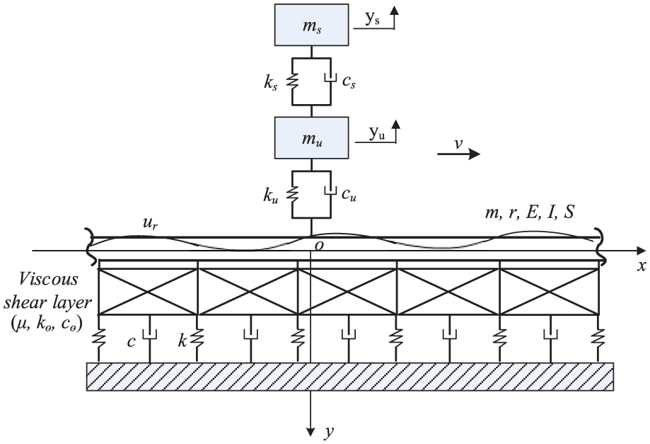
An infinite Timoshenko beam on a Pasternak foundation under a vehicular load.
Using Hamilton’s principle and Timoshenko beam theory, the governing equations of motion of this system can be obtained as follows (Ahmadian et al., 2008)


where w(x,t) and θ(x,t) are the deflection and rotation of the beam, respectively; m is the mass of the beam per unit length; E is the Young’s modulus; I is the cross-sectional moment of inertia; S and r are the shear rigidity and the radius of gyration of the beam, respectively; the dot over a variable denotes the differentiation with respect to time; the prime of a variable denotes the differentiation with respect to coordinate x; δ is the Dirac function; v is the vehicle velocity; and Pf and Mf are, respectively, the foundation simulated force and moment per unit length of the beam which are given as follows (Ahmadian et al., 2008)


where k, c, kθ, cθ, and µ are normal stiffness, normal damping, rocking stiffness, rocking damping, and shear viscosity coefficients of the foundation, respectively; and the vehicular load q(t) is given by (Lombaert et al., 2000)

where ur is the surface irregularity; cu and ku are damping and stiffness of vehicle unsprung components, respectively; and yu is vertical displacement of vehicle unsprung components, which is determined by the following two governing equations of motion of a quarter car model (Cebon, 1999)


where subscripts s and u denote sprung and unsprung components of the car model, respectively.
Equation (4) indicates that the computation of vehicular load q(t) is a coupled problem and thus requires simultaneously solving equations (1) and (5), particularly for the vehicle–bridge interaction problem (Gao et al., 2015; Yin et al., 2016). However, for the research of interest in this article, the vibration of the vehicle–road system, this coupled effect can be ignored because the stiffness of the road is much higher than that of the vehicle (Hao and Ang, 1998; Hunt, 1991; Ju, 2009; Lombaert et al., 2000). Consequently, the items (w and
Since the length of the beam is assumed to be infinite, the deflection, shear force, and moment of the beam vanish on both sides of infinite boundary (±∞), that is

Analytical solution
A moving coordinate system attached to the vehicle is first introduced

where subscript ≡ denotes the variable in the moving coordinate system.
According to the chain rule of differentiation, the following equations are derived
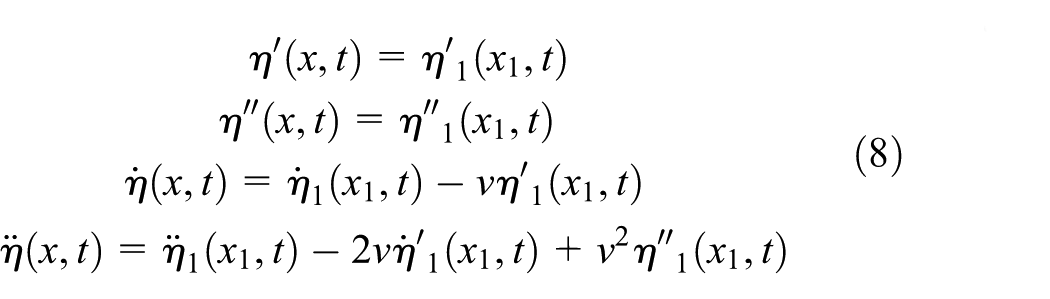
where η represents w or θ.
By substituting equations (7) and (8) into equation (1), the governing equations of motion of the system can be rewritten as follows


where x1 and t are omitted for brevity.
The road irregularity is assumed to be spatially harmonic with wavenumber kr (Lombaert et al., 2000)

where Ur is amplitude of the road irregularity. Using x = vt and ω = vkr where ω is the load circular frequency, equation (10) can be written in a temporally harmonic form

The resulting vehicular load is also harmonic, that is, q(t) = Qexp(iωt), where Q is amplitude of the vehicular load.
Assume w1(t) = W1exp(−ikxx)exp(iωt) and θ1(t) = Θ1exp(−ikxx)exp(iωt) where W1 and Θ1 are, respectively, amplitudes of the beam deflection and rotation in the moving coordinate system, and kx is the wavenumber of moving coordinate x1. Substituting w1(t) and θ1(t) into equation (9), one can obtain the governing equations of motion of the system in the frequency–wavenumber (ω − kx) domain


Similarly, the governing equations of motion of the vehicle in the frequency domain can be rewritten in a matrix form (Hao and Ang, 1998)

where Ys and Yu are amplitudes of ys and yu, respectively; A and B are defined as follows




where

where Δ = AssAuu − AsuAus is the determinant of the coefficient matrix in equation (13).
Equation (12) consists of two linear equations of Θ1 and W1. By eliminating Θ1, one obtains the beam deflection moving with the load in the wavenumber–frequency domain
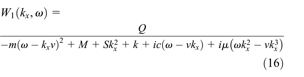
where

Combining the coefficients at the same order of kx, equation (16) can then be rearranged as follows

where C1–C9 are coefficients given in Appendix 1 and the denominator is usually termed as the characteristic equation.
Applying an inverse Fourier transform to equation (17) yields the following beam deflection in a general integral form
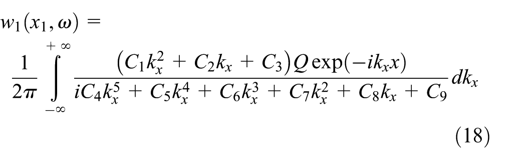
By employing Cauchy’s residue theorem, the analytical solution of equation (18) is given as follows
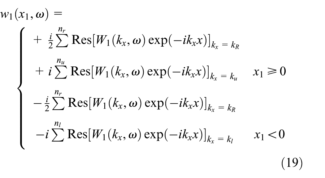
where kR represents the real poles of
Verification
By setting S = infinity, r = 0, c = 0, kθ = 0, cθ = 0, µ = 0, ω = 0, and neglecting the presence of the vehicle, the beam-foundation-vehicle system becomes an EB beam resting on a Winkler foundation under a moving point load with constant amplitude, which is referred to as the reduced system hereafter. The properties of the beam are EI = 363.35 kN m2 and m = 297.5 kg/m. The stiffness of the foundation is k = 77.17 MPa. The amplitude of the point load is 70 kN. The critical velocity of the reduced system, defined as
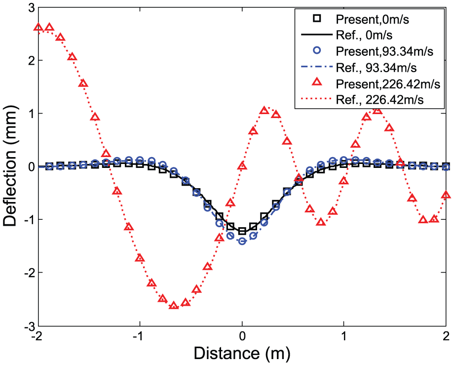
Deflection of an EB beam on a Winkler foundation under a moving point load.
A numerical example
In order to investigate the influences of the beam and foundation’s properties on the vibration characteristics of the beam, a numerical example is studied in the following sections. The properties of the Timoshenko beam are S = 100 MN and r = 0.1 m. The properties of the foundation are c = 10 kN s/m2, kθ = 13.8 MN, cθ = 5520 N s, and µ = 25 kN s (Rezvani and Khorramabadi, 2009). The properties of the vehicle are ms = 8900 kg, mu = 1100 kg, cs = 40 kN s/m, ct = 4 kN s/m, ks = 2 MN/m, and kt = 3.5 MN/m (Cebon, 1999); the amplitude of the surface irregularity is Ur = 0.01 m. Other parameters, such as m, k, and EI, are the same as in section “Verification.” Note that the critical frequency
In the following sections, the deflected shape versus load velocity is first studied, followed by the investigation of the influence of beam and foundation’s properties on the critical velocity, critical frequency, and their maximum deflections.
Deflected shape
The deflection of the beam is calculated using equation (19). Figure 3 shows the results for different load velocities. Two frequencies are considered: one is 20 Hz, higher than two critical frequencies of the vehicle but lower than the critical frequency of the reduced system; the other is 100 Hz, higher than all three critical frequencies. The deflected shapes are not symmetric because the vehicular load is moving and the damping of the system is considered. The position of the maximum deflection lags behind the load center, and this lag becomes larger as the vehicle velocity increases. These observations are consistent with the findings by Kim (1996) and Luo et al. (2015). When the load frequency is 20 Hz, the maximum deflection increases slightly as the load velocity increases, and more fluctuations can be observed behind the load but no fluctuation appears ahead of the load. When the load frequency is 100 Hz, the deflected shapes spread more widely and multiple peaks appear. In particular, the peaks in front of the load decrease as the load velocity increases, while peaks behind the load, the maximum deflection, are case-dependent and will be studied in detail in the following sections.
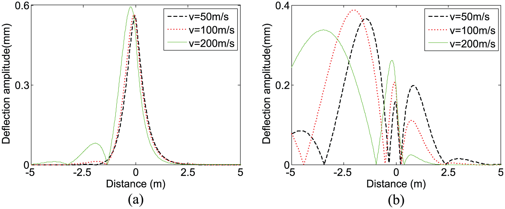
Deflection shape of the beam for different load velocities: (a) f = 20 Hz and (b) f = 100 Hz.
Critical velocity and maximum deflection
The maximum deflection of the beam is not only affected by the load velocity and frequency but also by the beam and foundation’s properties. The relationship between the beam’s maximum deflection and load velocity for various beam properties is shown in Figure 4. Generally, as the load velocity increases, the maximum deflection increases and then decreases after reaching an extreme value. The velocity corresponding to the extreme value of deflection is referred to as critical velocity. The critical velocity is not obvious in most of cases, which differs from the case of a beam on a Kevin foundation (Kim, 2005; Kim and Cho, 2006). This is mainly because of an extra viscous shear layer of the Pasternak foundation.
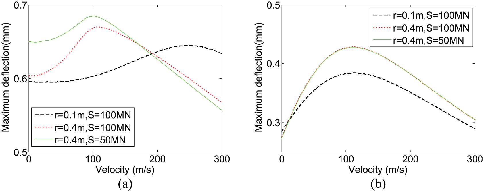
Maximum deflection versus vehicle velocity for different radii of gyration and shear rigidities of the beam: (a) f = 20 Hz and (b) f = 100 Hz.
When the load frequency is 20 Hz (see Figure 4(a)), the critical velocity decreases dramatically as the radius of gyration increases, but the corresponding maximum deflection increases. As the shear rigidity increases, the critical velocity increases, but its corresponding maximum deflection decreases. When the load frequency is 100 Hz (see Figure 4(b)), both the radius of gyration and the shear rigidity almost have no influence on the critical velocity, while its corresponding maximum deflection increases when the radius of gyration increases.
Figures 5(a) and (b) present the relationship between the maximum deflection of the beam and vehicle velocity for different shear viscosity coefficients of the foundation, when the load frequencies are 20 and 100 Hz, respectively. In the former case, if no shear viscosity exists, two critical velocities can be clearly observed, which have also been observed by Kim and Roesset (2003). These two peaks almost vanish when the shear viscosity is considered. The maximum deflection decreases as the shear viscosity increases. This decrease is more significant at the higher vehicle velocity. When the load frequency is 100 Hz, the critical velocity is rather small (less than 100 m/s) as compared with the 20 Hz counterpart. As the shear viscosity increases, the critical velocity increases, but its maximal deflection decreases.
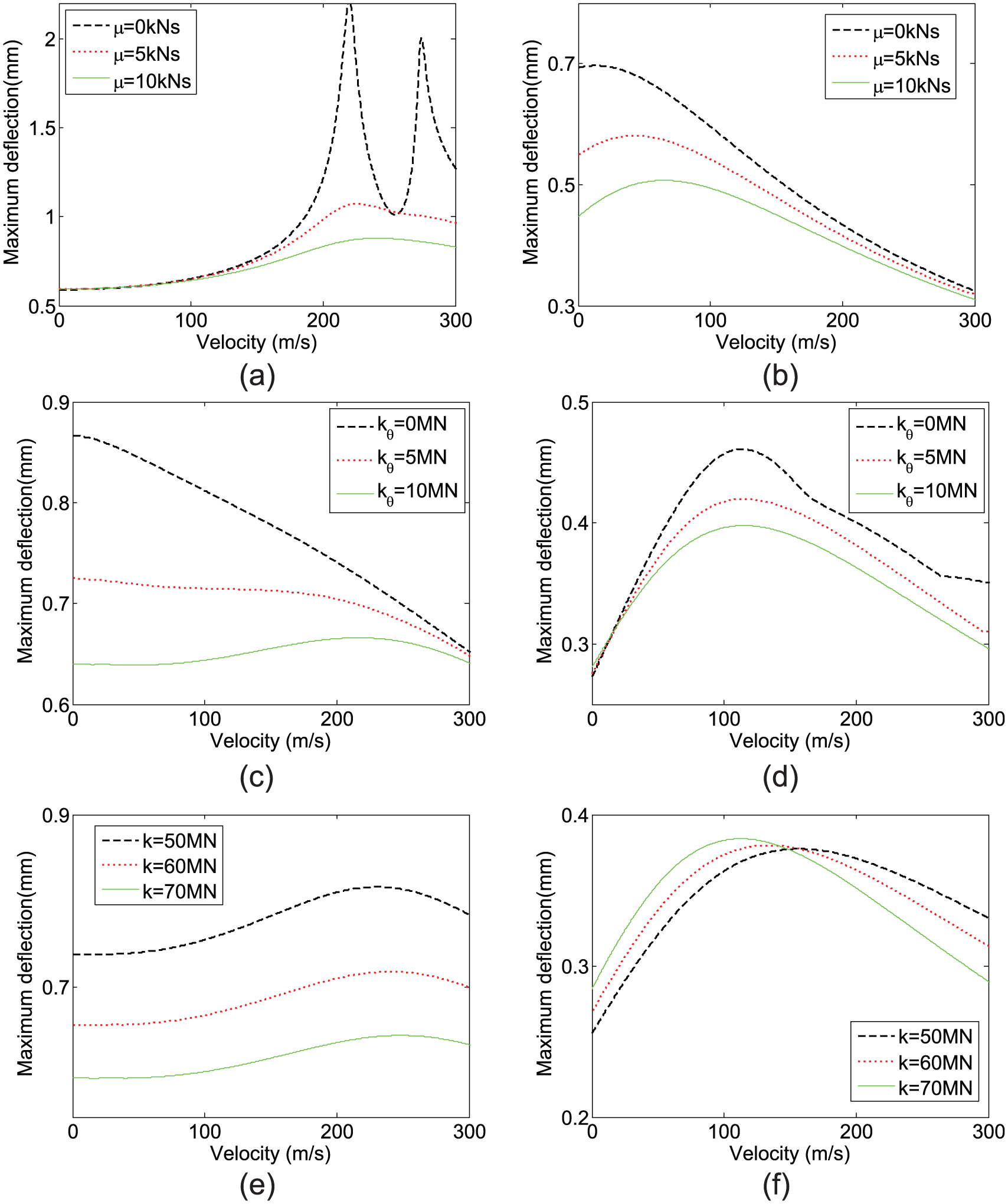
Maximum deflection versus vehicle velocity for different coefficients of the shear viscosity, rocking stiffness, and normal stiffness of the foundation: (a) f = 20 Hz, (b) f = 100 Hz, (c) f = 20 Hz, (d) f = 100 Hz, (e) f = 20 Hz, and (f) f = 100 Hz.
The effects of the rocking stiffness on the critical velocity and maximum deflection are shown in Figure 5(c) and (d), respectively. When the load frequency is 20 Hz, the critical velocity is difficult to identify. The maximum deflection decreases as the velocity increases for a relatively small rocking stiffness (say 5 MN). For a larger value (kθ = 10 MN), the deflection is almost constant regardless of the load velocity. For the case of 100 Hz load frequency, one critical velocity can be found. The corresponding maximum deflection decreases as the rocking stiffness increases.
Figures 5(e) and (f) illustrate the relationship between the maximum deflection and vehicle velocity for various normal stiffness coefficients of the foundation. At 20 Hz load frequency, one critical velocity can still be found. Its value is essentially identical (about 240 m/s) for all three cases, but the corresponding maximum deflection increases significantly as the normal stiffness decreases. In other words, the variation of the normal stiffness seems only affect the amplitude of the maximum deflection. At 100 Hz load frequency, the critical velocity is about 150 m/s, much lower than the 20 Hz counterpart. As the normal stiffness increases, this critical velocity increases, whereas its corresponding maximum deflection decreases.
Critical frequency and maximum deflection
The effects of the beam and foundation’s properties on the critical frequency and maximum deflection are investigated in this section. Two representative vehicle velocities, 100 and 200 m/s, are chosen. The former is lower than the critical velocity of the reduced system, and the latter is higher. Similar to the definition of the critical velocity, the frequency corresponding to the local maximum in the curve of maximum deflection versus frequency is regarded as a critical frequency.
Figure 6 shows the maximum deflection versus the load frequency for different radii of gyration and shear rigidities of the beam. Four critical frequencies can be generally observed: the first two are associated with motions of the vehicle body and tire, and the other two are associated with beam vibrations. The increase in the shear rigidity results in a very small decrease in the maximum deflection, while four critical frequencies are almost not affected. The increase in the radius of gyration, subsequently increasing the stiffness of the beam, does not necessarily result in smaller maximum deflection. Examples can be found in Figure 4(b), in the regions 20–50 Hz and 85–100 Hz of Figure 6(a), and in the region 85–100 Hz of Figure 6(b). This is because the increase in the radius of gyration also decreases the third and fourth critical frequencies, which in turn affects the variation of the maximum deflection curve.
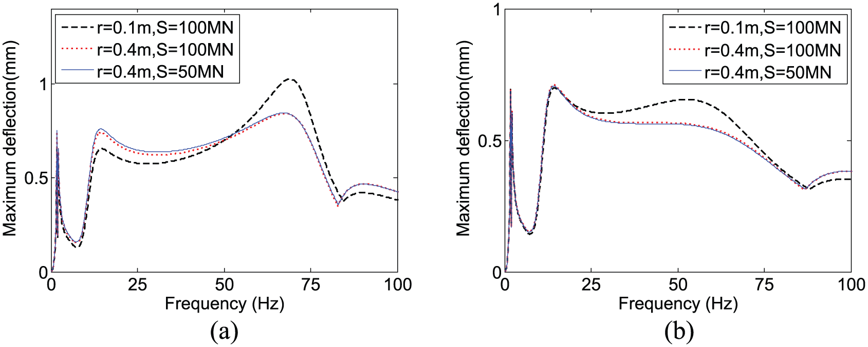
Maximum deflection versus vehicle frequency for different radii of gyration and shear rigidities of the beam: (a) ν = 100 m/s and (b) ν = 200 m/s.
The effects of the shear viscosity coefficient of the foundation on the critical frequency and maximum deflection are shown in Figure 7. The maximum deflections at all frequencies decrease as the shear viscosity coefficient increases. When no shear viscosity is considered, the sharp peak corresponding to the third critical frequency appears. This peak almost vanishes at a higher shear viscosity in Figure 7(b). As the shear viscosity increases, the third critical frequency increases, while the fourth one decreases. As expected, the first two regarding vehicle motions are not affected by the shear viscosity.
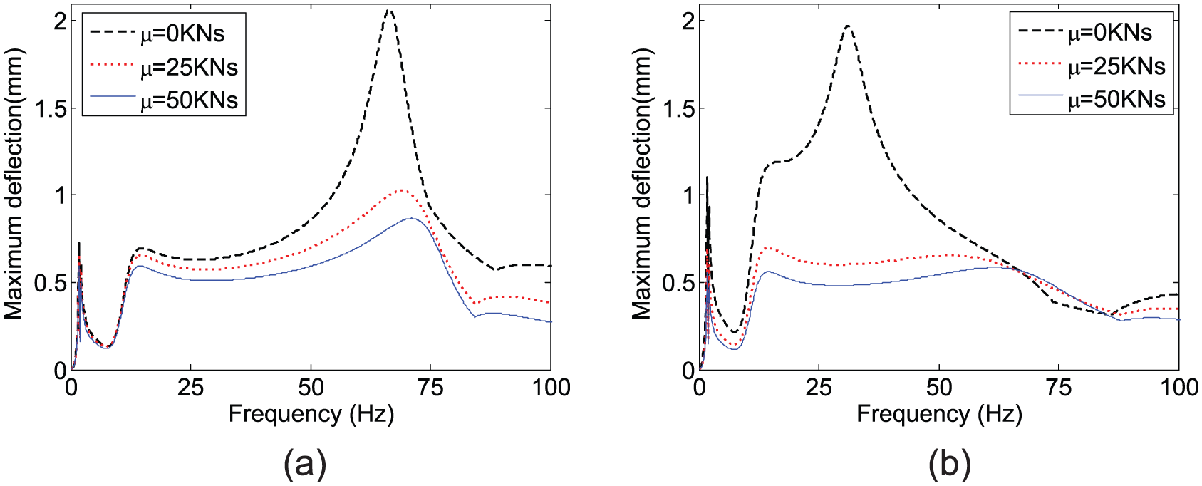
Maximum deflection versus vehicle frequency for different shear viscosity coefficients of the foundation: (a) ν = 100 m/s and (b) ν = 200 m/s.
Figure 8 shows the effects of the rocking stiffness and normal stiffness of the foundation on the maximum deflection and critical frequency when the vehicle velocity is 200 m/s. Generally, the increase in rocking stiffness or normal stiffness leads to a smaller maximum deflection. Some exceptions can also be found in the region of 0–100 m/s in Figure 5(f), in the region 50–60 Hz of Figure 8(a), and in the region 50–75 Hz of Figure 8(b). This is because the variation of the rocking stiffness or normal stiffness affects both the critical velocity and the last two critical frequencies, which in turn influences the curves of the maximum deflection. Although the first two critical frequencies remain the same, the third one increases as the rocking stiffness or as the normal stiffness increases, and the fourth one also increases as the rocking stiffness increases or as the normal stiffness decreases.
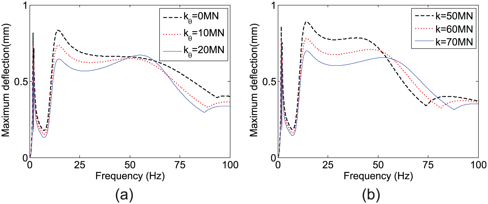
Maximum deflection versus vehicle frequency for different coefficients of the (a) rocking stiffness and (b) normal stiffness of the foundation when v = 200 m/s.
Conclusion
The vibration of an infinite Timoshenko beam on a Pasternak foundation subjected to a concentrated vehicular load has been analytically investigated. A quarter car and harmonic irregularity road are considered to calculate the vehicular load. The analytical formulae are validated by comparison with the existed solution of an EB beam on a Winkler foundation. A numerical example is used for parametric study of the beam’s vibration. Based on the numerical results, the following conclusions can be drawn:
The deflected shape of the beam is not sensitive to the load velocity when the load frequency is relatively low as compared with the critical frequencies of the system, while the deflected shape spreads widely and multiple peaks appear when the load frequency is high.
The critical velocity is not obvious, mainly due to the extra viscous shear layer of the Pasternak foundation. When the load frequency is low, the critical velocity decreases as the radius of gyration increases or as the shear rigidity decreases, while the critical velocity is insensitive to both properties when the load frequency is high. The influence of foundation properties on the critical velocity is rather complicated, and the maximum deflection decreases with an increase in the shear viscosity, rocking stiffness, and normal stiffness (only at a low frequency).
Four critical frequencies can be observed in the deflection versus frequency curve. The first two, which are associated with motions of vehicle body and tire, are constant regardless of the variations of the beam and the foundation’s properties. The third critical frequency increases with an increase in the shear viscosity, rocking stiffness, and normal stiffness, or with the decrease in the radius of gyration. The fourth critical frequency increases with an increase in the normal stiffness, or with the decrease in the radius of gyration, shear viscosity, and rocking stiffness. Both values of the critical velocity and critical frequency affect the maximum deflection and lead to some exceptions in the curves against the beam and the foundation’s properties.
Footnotes
Acknowledgements
The first author thanks the Research Grants Council of the Hong Kong Special Administrative Region for the Hong Kong PhD Fellowship award.
Declaration of Conflicting Interests
The author(s) declared no potential conflicts of interest with respect to the research, authorship, and/or publication of this article.
Funding
The author(s) disclosed receipt of the following financial support for the research, authorship, and/or publication of this article: This work was supported by the Hong Kong Polytechnic University (Project Nos G-YN95 and G-YBC7).
Appendix 1