
Abstract
A series of wind tunnel tests were conducted to investigate the effects of parapets of different configurations and various heights on the wind loading of a flat-roofed low-rise building. Local wind pressures, area-averaged peak pressures, and overall roof uplift force on the roof were determined. Spectral analysis was also performed to better understand the mechanism of how the presence of parapets affects the wind effects on the building. Additional attention was given to the power spectral density and non-Gaussian features of the area-averaged wind pressures. The results show that low parapets (h/H no more than 0.1) often increase suctions in the roof corner region. The presence of high parapets results in a decrease in the wind effects over the roof corners; however, it also leads to a growth of the uplift force over the entire roof. Comparisons among many different parapet configurations show that the ones with the raised and bottom-slotted corners help to efficiently alleviate the worst suction on flat roofs. In addition, the high parapet acts as a low-pass filter, filters out parts of the high-frequency energy in the approach flow, and stabilizes the wind pressure distribution on roof.
Keywords
Introduction
Historically, wind hazards have resulted in tremendous economic losses all over the world. A substantial amount of post-disaster damage studies and insurance claim data reveals that failed roof coverings and rooftop accessories are usually the leading cause of damages to residential dwellings (Applied Research Associates 2008; Federal Emergency Management Agency, 2005; Huang et al. 2011; Huang et al. 2014; Peng et al. 2016). Loss of roof covering often compromises its water shedding ability and consequently causes water to intrude into building, leading to interior water damages. Additionally, displaced roofing could impact neighboring buildings in forms of wind-induced debris. These facts highlight a need for seeking effective and economical mitigation devices to improve the building envelope performance against high winds.
In the past decade, attempts have been made toward mitigating extreme wind pressures on a gable or hip roof via simple modifications to the configurations of roof edges or the installation of aerodynamic mitigation devices (Bitsuamlak et al., 2012; Huang et al., 2014). Common mitigation techniques include trellises, roof extension of gable ends, and sideways extensions of wall (for recent reviews see Asghari Mooneghi and Kargarmoakhar, 2016). These methods can change the flow pattern over the roof leading edge or corners and consequently mitigate the worst suctions in these areas.
As a common architectural element on a flat roof, parapets are often mounted in edge and corner areas where extreme wind suctions occur. Generally, the height of parapets has been recognized as a key factor to their aerodynamic effects on the wind effects of building. For instance, Baskaran and Stathopoulos (1988) conducted a series of wind tunnel tests and found that roof corner suctions may increase significantly when less than 1 m high parapets were applied on any buildings. The experimental results in Stathopoulos et al. (1999) showed that the magnitude of the mean suction at roof corners depends on the relative height of parapets, h/H (h and H represent the parapet and building eave height, respectively), rather than the absolute parapet height. Kopp et al. (2005a) investigated the effect of the parapet height via a series of wind tunnel tests and concluded that the lower perimetric parapet acts to increase the suction coefficients for the case of h/(H + h) ≤ 0.17 or h/H ≤ 0.20, whereas the higher parapets (i.e. h/(H + h) > 0.23 or h/H > 0.25) could reduce the corner and edge suctions by over 50%.
In addition, the parapets with various configurations have been well examined in an effort to determine an optimum device for mitigating wind loading on flat roofs. Surry and Lin (1995) investigated the sensitivity of high suctions at the corner to the minor modifications of the roof corner geometries through wind tunnel test and suggested that the porous parapet among the aerodynamic measures provided the most significant effect of mitigating the worst suction. To evaluate the effectiveness of six parapets, Pindado and Meseguer (2003) conducted many wind tunnel tests and found that the low-height parapets with a medium porosity and cantilevered parapets had better performance in reducing suction than continuous solid parapets. Based on the wind tunnel results, Kopp et al. (2005a, 2005b) contended that spoilers and porous perimetric parapets could significantly reduce the suction in the corner and edge regions. Furthermore, several wind tunnel tests were carried out by Suaris and Irwin (2010) using a low-rise building model with a 3:12 roof slope, where parapets only at the corners and at the ridge were mounted. It was found that 0.2 m porous parapets only installed at corner with a perforation ratio of 33% resulted in a 60% reduction in the peak coefficients in the corner region.
Except Kopp et al. (2005a, 2005b, 2005c), there are few systematic studies that have been carried out on the effects of parapets using a large-scale wind tunnel model. The purpose of this study is to re-evaluate the effects of parapets with various heights and configurations on the peak local and area-averaged wind pressure coefficients of flat roofs. Moreover, there is limited information on the mechanism of how parapets affecting the turbulence characteristics on low-slope roofs. Therefore, the effects of parapets on the power spectral densities of the wind pressures acting on the roofs were investigated and possible implications were provided. Further to that, particular attention was also given to the power spectral density and non-Gaussian features of the area-averaged wind pressures.
Wind tunnel test
Experimental setup and wind tunnel simulation
Wind tunnel studies were conducted in the TJ-2 Atmospheric Boundary Layer (ABL) Wind Tunnel at the Tongji University. TJ-2 ABL Wind Tunnel has a testing section of 3.0 m in width, 2.5 m in height, and 15.0 m in length with wind velocity ranging from 0.5 to 68 m/s. Two sets of measuring instruments were used in the wind tunnel test: (1) wind velocity measuring system: The reference wind velocity in the test was measured and monitored by the Pitot tube and micro-pressure differential meter. (2) Pressure measuring, recording, and data processing system: the system consists of a DSM3400 electronic pressure scan valve system (512 channels, 10 in H2O low-pressure transducers, USA), a micro-computer and a specially developed software. Huang et al. (2011) have well described the equipment and data acquisition system in the wind tunnel.
A length scale of 1/20 was chosen to better model rooftop parapets and to measure the wind pressures over corners. The test model is made of polymethyl methacrylate sheet (see Figure 1(a)). The prototype of the model is a 10 m long by 6 m wide by 8 m high flat-roofed building. A total of 356 taps were drilled into the roof and walls to simultaneously measure wind pressures on the model. Figure 1(b) depicts the layout of all taps and the definition of the wind attack angle. In this study, three square areas in the corner and edge regions were chosen to investigate area-averaged wind effects, which are manifested as “Block 1,”“Block 2” and “Block 3” in Figure 1(b).
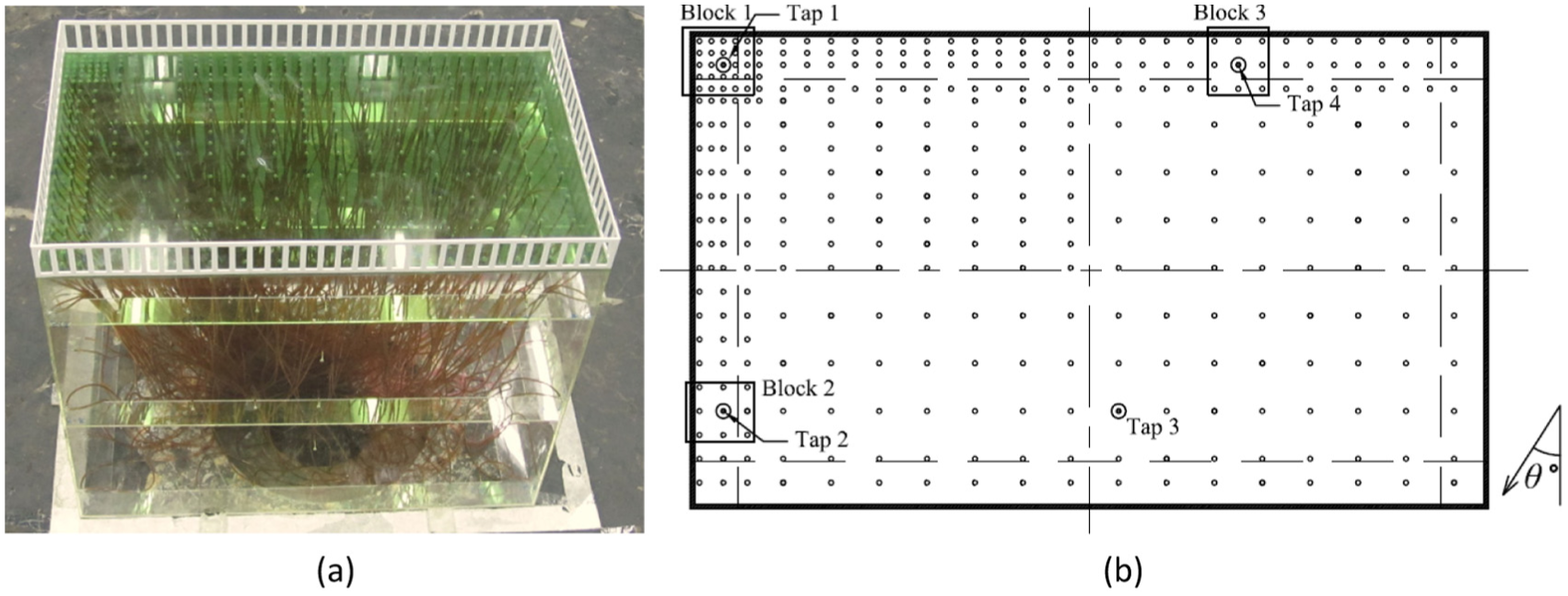
(a) 1/20 wind tunnel test model and (b) building plan view and tap layout.
A boundary layer flow over open terrain was simulated in the wind tunnel, with turbulence intensities (Iu) at the mean roof height equal to approximately 20%. The simulated mean velocity and turbulence intensity profiles are presented in Figure 2(a). The figures show that the simulated mean wind velocity and turbulence intensity profiles are in reasonable agreement with the target profiles for Terrain Category II (open terrain) from Architectural Institute of Japan (AIJ) (2004).

(a) Wind velocity and longitudinal turbulence intensity profiles and (b) longitudinal wind velocity spectrum at a height of 10 m (full scale).
Figure 2(b) shows the longitudinal wind power spectral density (PSD) at a height of 10 m, along with target spectrum (Von Karman, 1948). There is a discrepancy between the measured and Von Karman spectra, primarily due to the large length scale selected, which is indicative of a mismatch of the longitudinal turbulence scale by about a factor of 2 based on the shift in the high-frequency region of spectra (the turbulence integral length scale can be obtained using PSD). The mismatch in the power spectral densities could lead to the difference between simulated and full-scale fluctuating pressures (Asghari Mooneghi, 2014; Asghari Mooneghi et al., 2014, 2015; Surry, 1991). However, this level of mismatch is likely to be inconsequential for point pressures and averages over small areas where the pressure patterns are primarily dominated by mean roof height and configurations of edges (Ho et al., 2005).
The surface pressure acting at each tap was measured at a reference wind speed of Uref = 7.34 m/s and was re-referenced to the mean roof height (8 m) with a sampling rate of 312.5 Hz. The wind angles measured range from 0° to 360° at an interval of 15° and time duration for each record is 10 min in full scale.
In this study, four groups of parapets, that is, (1) perimetric solid parapets of varying heights, (2) partial parapets, (3) parapets with different geometries, and (4) parapets with different porosities, were tested to alleviate the adverse wind pressures and determine the most economical and effective one.
Data processing
The wind pressure coefficient at a specific tap, Cpi(t), is determined by
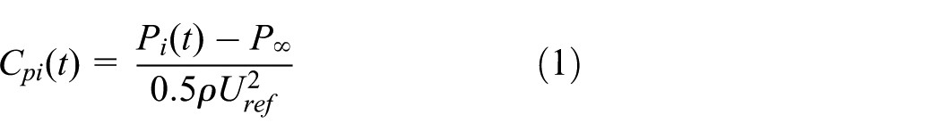
where Pi(t) represents the pressure time history measured at the ith tap, P∞ is defined as the static pressure at infinity, ρ is the air density, and Uref is denoted as the mean wind velocity of the approach flow at the reference height (i.e. 8 m in full scale). The mean and fluctuating pressure coefficients, that is, Cpmean and Cprms, amount to the average value and standard deviation of the pressure coefficient time series, respectively.
The most appropriate technique to estimate a peak pressure coefficient from wind tunnel data is not a settled issue. Common techniques used for the peak estimation include an instantaneous observed peak during a sampling period (Stathopoulos, 1979), the mean of several observed peaks (Holmes et al., 1989), the Lieblein BLUE fitting estimation (Lieblein, 1974), the classic peak factor method (Davenport, 1964), and the translation method (Peng et al., 2013, 2014; Yang et al., 2013). In this study, the peak wind loads on the flat-roofed building were estimated using the classic peak factor method. This procedure was proposed by Davenport (1964) based on the assumption that the wind pressure be a closely Gaussian process. The maximum or minimum peak wind pressure coefficients are given by
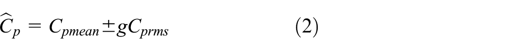
where g is the peak factor that can be calculated by
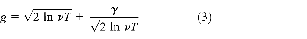
in which ν is the zero up-crossing rate; γ, that is, Euler constant, is equal to 0.5772; and T represents the time duration over which the maximum value is required. To date, two methodologies have been available for determining the zero up-crossing rates, consisting of empirically counting and power spectra ratio. The counting method was employed in this study to estimate the zero up-crossing rates.
The time series of area-averaged wind pressure coefficient is determined by simultaneously combining pressures of taps within a region as follows

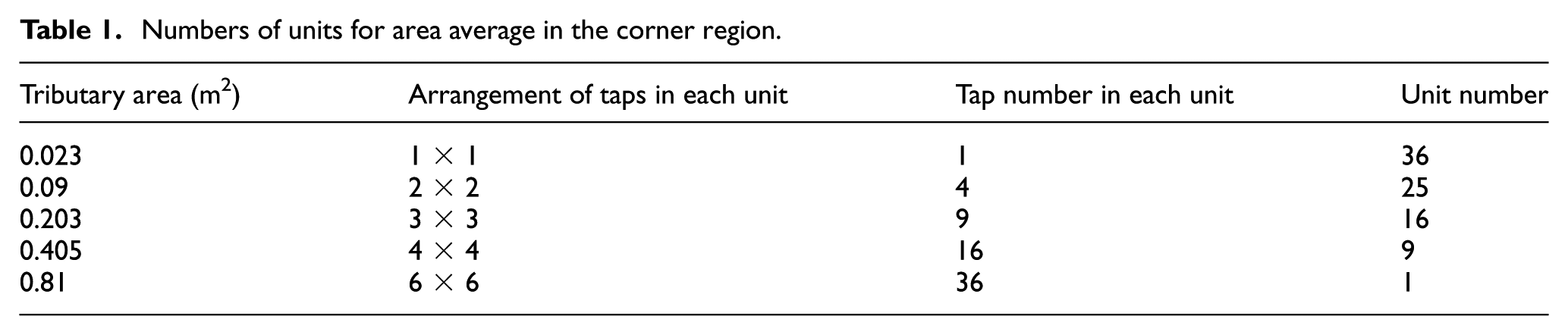
in which Cpavg(t) is the area-averaged pressure coefficient in the prescribed region on roofs; Ai represents the tributary area of tap i. The details of the unit (area) parameters of the area division on the roof corner are listed in Table 1 (total tap number in the corner region is 36).
Numbers of units for area average in the corner region.
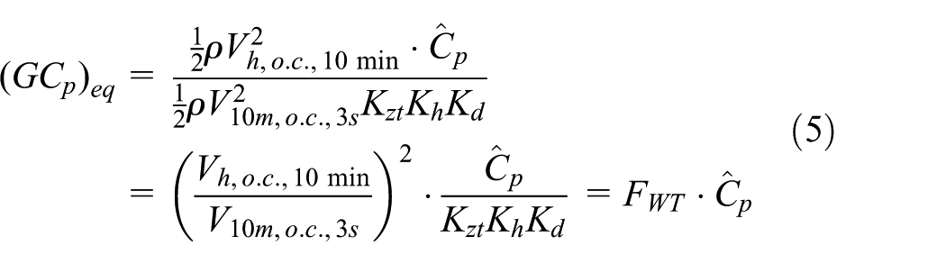
ASCE/SEI 7-10 (2010) provides a guideline for the design of the building envelope against winds. The codified pressure coefficients (GCp) in ASCE/SEI 7-10 (2010) correspond to a 3-s gust velocity at the mean roof height. For the purpose of direct comparison with the codified values in ASCE/SEI 7-10 (2010), the wind tunnel results need to be converted. The methodology for the conversion has been described in Kopp et al. (2005a)
where (GCp)
eq
is the equivalent wind pressure coefficient based upon 3-s gust wind speed (Vh,o.c.,3s) at the mean roof height in the open country (o.c.) terrain; Ĉp represents the peak wind pressure coefficient from the wind tunnel test, corresponding to the 10-min velocity at the mean roof height in the o.c. terrain; Kh is determined either from the interpolation or using the formula in Table 30.3-1 of ASCE/SEI 7-10 (2010) that is equal to 0.95; Kzt and Kd are set to be unity.

in which the reciprocal of the first term of the right-hand side is actually the gust factor, GF(600,3) = 1.52/1.10 = 1.38, taken from Figure C26.5-1 in ASCE/SEI 7-10 (2010); and the second term of the right-hand side can be estimated using the velocity profile (see Figure 2(b)) and is equal to 0.80.64. Substituting the data into equation (5) yields a coefficient FWT of 0.4727.
Results and discussion
Comparison with previous data
The Tokyo Polytechnic University (TPU) developed comprehensive sets of aerodynamic databases (http://www.wind.arch.t-kougei.ac.jp/system/eng/contents/code/w_it) that are publicly available and provide a source encompassing a substantial amount of experimental data on the wind effects of low-rise buildings. A similar model in an identical approach flow condition was chosen to validate the present experimental results.
The model from the TPU database has a length-to-width ratio of 3:2 and a height-to-width ratio of 1:1 with a length scale of 1/100. The reference height is chosen at the mean roof of the building and corresponds to 16.0 m in full scale. The tests were conducted in the Boundary Layer Wind Tunnel, 2.2 m wide by 1.8 m high, located in the Tokyo Polytechnic University, Japan. The mean velocity profile for the chosen model herein has a power exponent of 0.40, which is close to the simulated oncoming flow condition in this study (a power exponent of 0.32 as shown in Figure 2).
Figure 3 presents the mean pressure contour plots of two models for the oblique wind. It was found that the present data is consistent with the result from the TPU database. Both models reveal the similar vortical “footprints” on roof. Alternatively, the pressures magnitudes and distributions for two models are consistent. The slight differences primarily result from the discrepancies of simulated wind fields (e.g. terrain and length scale) and model geometries (e.g. eave height, width, and length of model). The comparison demonstrates that the present wind tunnel tests provide reliable results.

Mean wind pressure contour plots for oblique wind direction: (a) the TPU aerodynamic database and (b) the present model.
Area-averaged wind pressures
Most of the previous researches on the area averaging primarily focused on its influences on the magnitude of the peak or mean wind pressure coefficient, but seldom investigated its effects on the frequency domain as well as the non-Gaussian features of the wind pressure record. Actually these investigations can contribute to better understanding and interpreting the parapets’ aerodynamic effectiveness on the mitigation of wind pressures. For this reason, the analysis about the area averaging influence on the frequency domain characteristics and non-Gaussian features was analyzed in the present study.
The single tap pressure time history for analysis was directly taken from the experiment, whereas the area-averaged pressure coefficient record within the region being considered was obtained using equation (4). Three block areas and three taps were chosen herein for analysis. Their locations and designation could be found in Figure 1(b).
The tap and area-averaged wind pressure time histories obtained from Block 1 at 0° and 315° wind azimuths are shown in Figure 4. As compared with the spatially averaged pressure record, the single-tap time series are more fluctuating and unsteady. To illustrate the area averaging influence on the frequency domain, the PSDs of single-tap and area-averaged records are presented in Figure 5. It was observed that the high-frequency end of single-tap record is higher than area-averaged record.
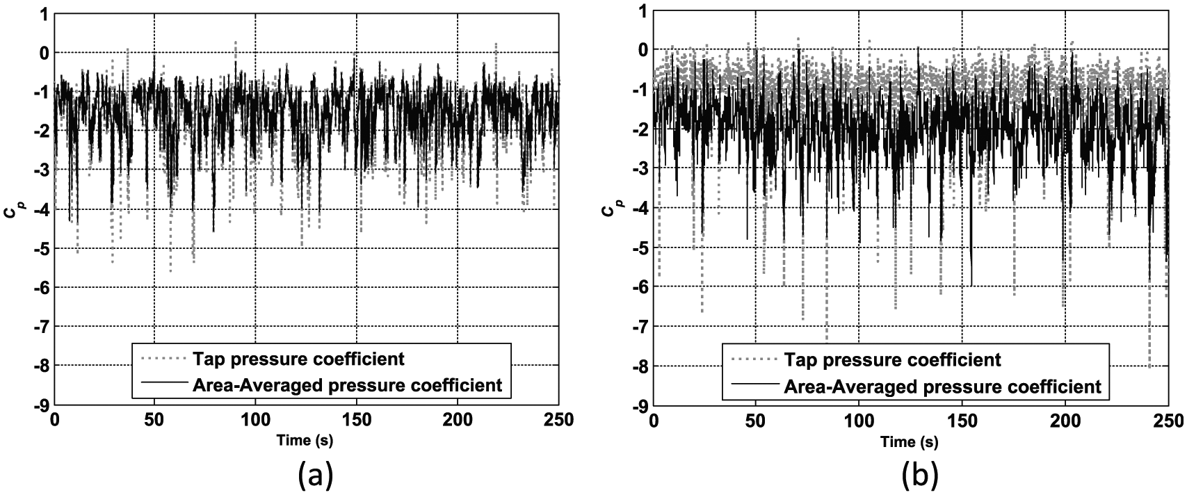
Time histories of single-tap pressure coefficient (Tap 1) and area-averaged pressure coefficient (Block 1): (a) 0° wind angle and (b) 315° wind angle.
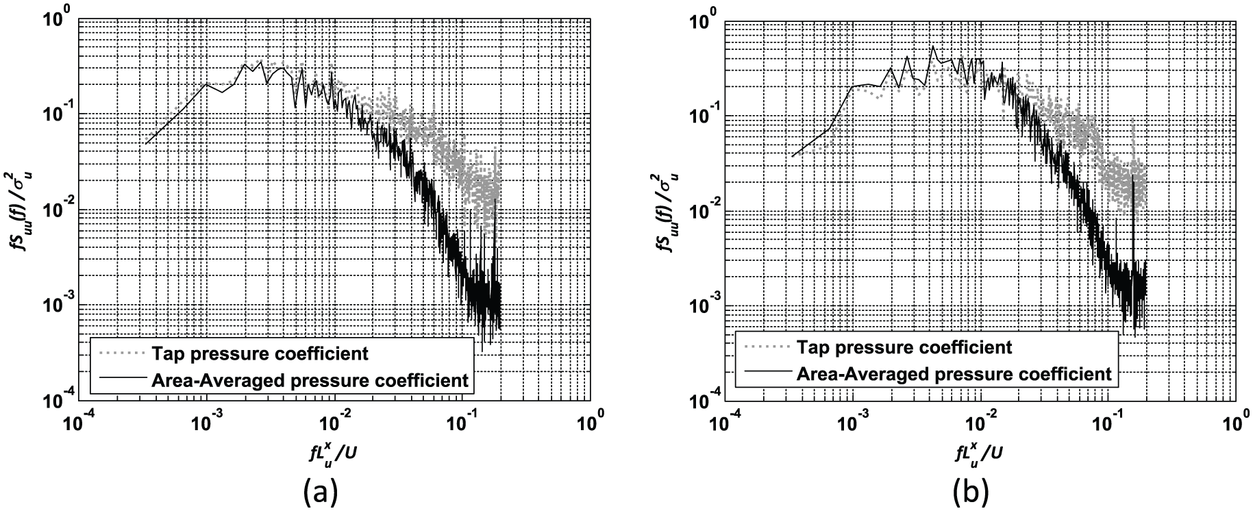
PSDs of single-tap pressure time series (Tap 1) and area-averaged pressure time series (Block 1): (a) 0° azimuth and (b) 315° azimuth.
Figure 6 presents the PDFs obtained from the tap and area-averaged time records of Block 1 for the oblique wind, and standard normal distribution curve. It was observed that the skewness (sk) and kurtosis (kt) of the single-tap pressure record (Tap 1) are −3.39 and 19.62, whereas those are −0.80 and 4.49 for the area-averaged time series (Block 1). The comparison reveals that the employment of area averaging weakens the non-Gaussian features of the measured wind pressure records. Based upon the central limit theorem, given certain conditions, the mean of a large number of random variables independently drawn from the same distribution is distributed approximately normally, irrespective of the form of the original distribution (Rice, 2007). Although the statistical characteristics of taps within Block 1 may not be exactly the same, the spatial mean of the records at these taps are forced to get close to the normal distribution by the spatial averaging. Figure 6 is useful in an anecdotal sense to show the influence of area averaging on the strongly non-Gaussian case. However, valid conclusions cannot be drawn only based on this plot. This study also applies this comparison methodology to other two bays at two wind directions. Figure 7 shows the two measures of non-Gaussian features of the tap and averaged wind pressures for three blocks at two wind azimuths. It can be seen that the area averaging tends to reduce the non-Gaussian features of wind pressures, regardless of the locations. It was noted that the area averaging is more effective to weaken non-Gaussianities of the strongly non-Gaussian wind pressures than the mildly non-Gaussian ones.
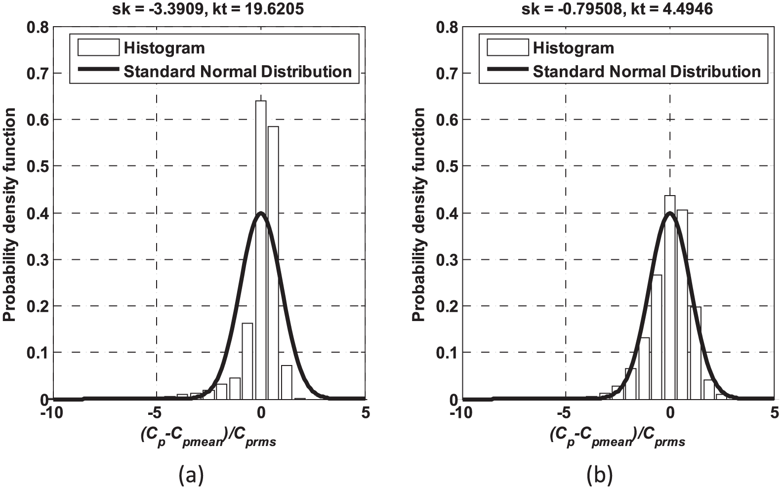
(a) PDF of single-tap pressure coefficients at wind angle of 315° (Tap 1) and (b) PDF of area-averaged pressure coefficients at wind angle of 315° (Block 1).
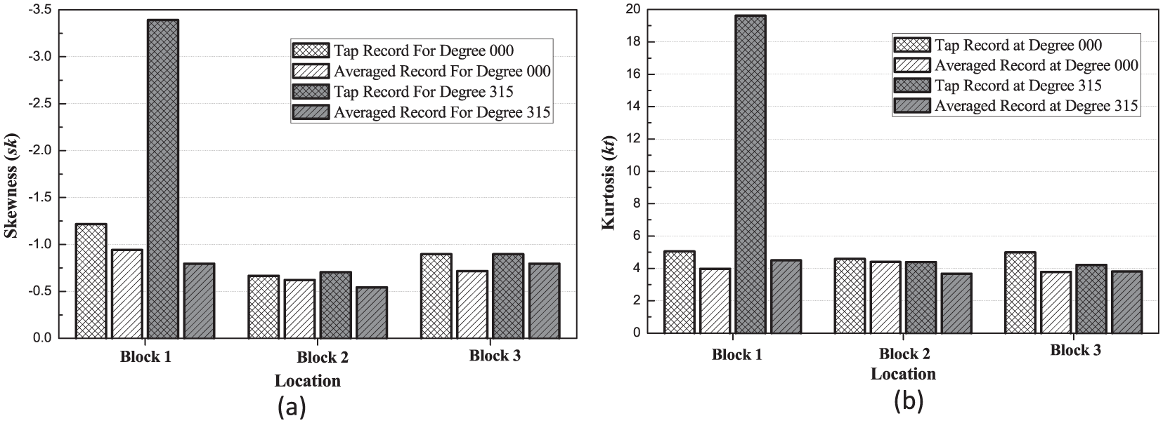
Area-averaging effect on non-Gaussian features of wind pressures: (a) Skewness and (b) Kurtosis.
Perimetric parapets of varying heights
The installation of perimetric parapet usually serves to lift the vortices up, which could result in a reduction of suctions at corners. However, its effect of mitigating wind pressure is in relation to the relative height of parapets. To gain an understanding of the physical nature of the flow around the building, and how parapets affect the flow pattern, eight parapets with various heights were considered and analyzed, as listed in Table 2.
Worst mean and peak tap pressure coefficients from all wind directions for the models with various height parapets.
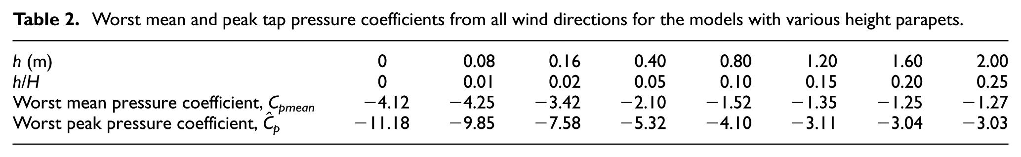
Figure 8 depicts the mean wind pressure coefficient contour plots of the models with eight parapet heights at a wind angle of 315°. It can be seen that as the parapet height increases, the mean wind pressure variation becomes milder, implying that the influence of the conical vortices on the pressure distribution is weakened. In other words, the presence of solid parapets helps to alleviate the worst mean wind loads at the roof corner and make the pressures over the roof more uniformly distributed for this wind direction. However, when the parapet height is more than 1.2 m, that is, h/H = 0.15, the wind pressure mitigation is significantly inhibited.
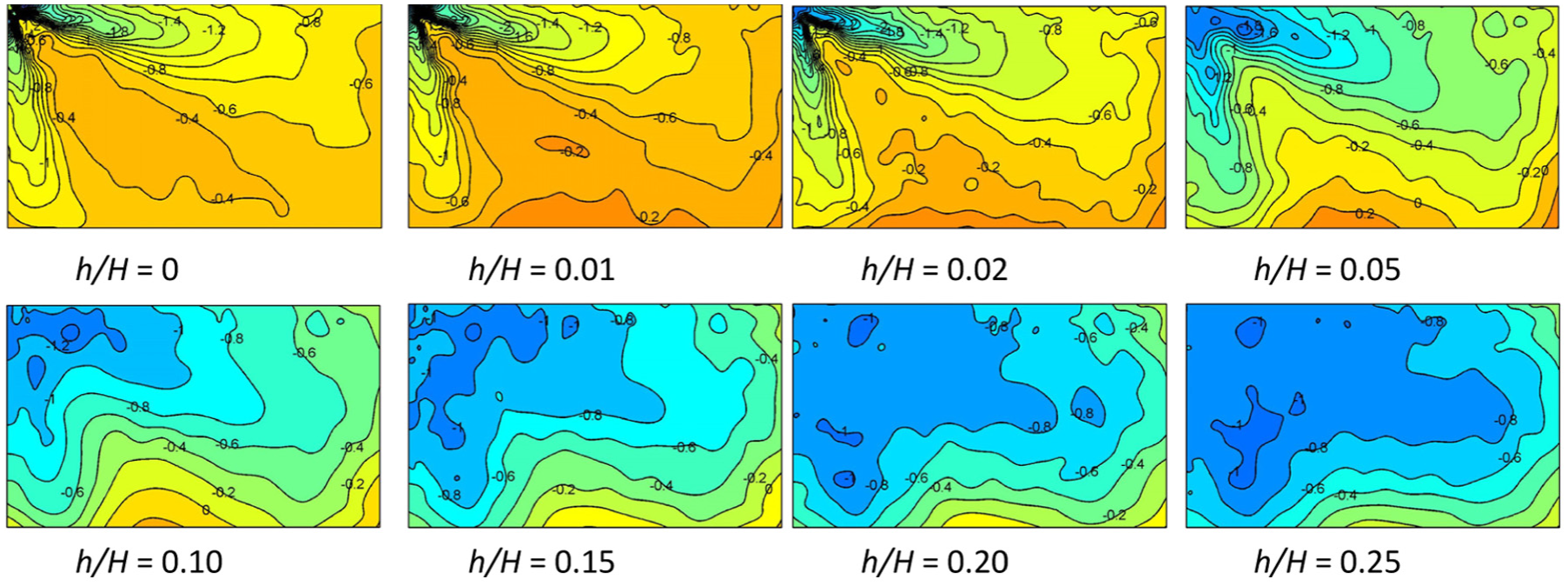
Mean pressure contour plots at wind angle of 315°.
Table 2 provides the worst mean and peak tap pressure coefficient from all wind directions for the models with various height parapets. It is clear that a relatively low parapet (h/H ≤ 0.01) may lead to the slight increment of the unfavorable mean wind pressure in magnitude; however, as the parapet height increases, the worst mean wind pressure may dramatically decrease in magnitude. When the parapet height increases to a certain value (i.e. h/H ≥ 0.15), the negative mean and peak pressures become stable.
In addition to the effect of parapet on the single-tap pressure, its effect on the area-averaged wind pressures needs to be considered. The area-averaged peak pressure is of main concern for the design when the large tributary area is considered.
To directly compare with the pressure coefficient values provided in ASCE/SEI 7-10 (2010), the peak pressure coefficient obtained from the wind tunnel test needs to be converted into GCp and the overall procedure has been explicitly elucidated in section “Data processing.” Figure 9 shows the variation of GCp in the corner region with the loading tributary area. It can be obtained that most of the worst averaged pressure coefficients significantly decrease as the tributary area increases. However, the variation of negative peak pressure coefficient is not sensitive to the selection of the tributary area when the parapet height is greater than or equal to 1.2 m.
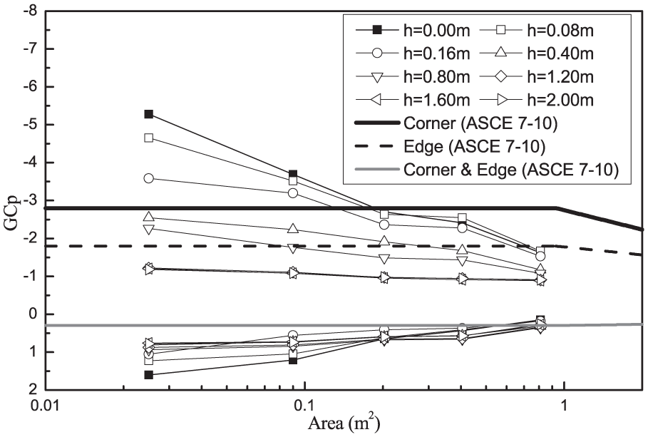
Worst pressure coefficients in the corner region from all wind directions.
The black solid line in Figure 9 represents the negative codified values for the corner region in ASCE/SEI 7-10 (2010) and the black dashed line is the negative designed values for the edge region. The positive peak wind pressure coefficient for the corner and edge zones in ASCE 7-10 is represented by the gray solid line in the graph. As can be seen in Figure 9, most of the downward (positive) peak wind pressure coefficients were found to be larger than the value specified in ASCE/SEI 7-10 (2010), which coincides with the results in Kopp et al. (2005a). It was also stated in Kopp et al. (2005a) that this is significant when combined with other loads (snow and water). Besides, the negative peak pressure coefficients moderately decrease in magnitude with the parapet height. It is noteworthy that GCp around the corner is basically regardless of the tributary area and the height of parapets when h ≥ 1.2 m. Plus, It was found that when h is not less than 0.8 m, the roof corner regions can be treated as the edge region, which is consistent with the specification in the ASCE 7 - i.e. the edge zone coefficients can be used in the design of the corner zone in the case of h not less than 0.9 m.
To better understand the response of structures with parapet under the wind, it is necessary to evaluate the variation of roof uplift wind load with the height of parapets. For convenience, the block and roof uplift force coefficients, CU(t), were invoked herein to represent the coefficients of the area-average wind pressure acting on Block 1 and whole roof. The time series of the uplift force coefficients over a specific roof section were determined by taking the area-weighted average of the pressure records for all pressure taps within this area.
Figure 10 presents the variations of the corner and global uplift coefficients with parapet heights. When the relative height h/H is more than 0.1, the uplifts acting on Block 1 decrease with increasing parapet heights. However, when h/H is relatively small, the presence of the parapet slightly increases the corner wind force, as shown in Figure 10(a). It was observed that the effects of parapet heights on the overall roof uplift are significantly different from those observed on the corner wind force. More specifically, the lower parapets tend to reduce the overall roof uplift, whereas the higher ones make the contrary effect.

Variation of uplift coefficient at the wind direction of 315° with parapet relative height: (a) Block 1 and (b) overall roof.
Partial parapets
Due to the complex and transient flow pattern around the roof corner, even the minor modifications of parapet (e.g. raising or slotting the corner of parapet) could result in dramatic variation in wind pressure distribution. To examine the effectiveness of these modifications, five types of partial parapets (see Figure 11) with slotted or raised corner are compared against the perimetric parapet. The heights of the parapets are set to be 0.8 m.

View of models with various partial parapets. Note the height of parapets is equal to 0.8 m: (a) solid, (b) isolated, (c) corner-raised, (d) bottom-slotted, (e) top-slotted, and (f) castellated.
The mean wind pressure contours in the 315° wind direction for several parapets are provided in Figure 12. As can be seen in these graphs, the corner-raised parapet is superior to the other two in mitigating the corner suction or uplift force. In comparison with no parapet test case, the presence of isolated parapets slightly reduces the mean pressure in the windward roof corner. Nevertheless, its aerodynamic mitigation effect is inferior to perimetric parapets.
Mean pressure contour plots at the wind angle of 315° (h = 0.8 m): (a) isolated, (b) corner-raised, and (c) castellated.
The comparison of the effects of all partial parapets on wind pressures in the corner region taking the spatial averaging into account was performed. Figure 13 presents the worst peak pressure coefficients in the corner region obtained from all wind directions with tributary areas. It seems that the isolated parapet and parapet with the top-slotted corner are not as effective as the perimetric solid parapet of similar height. As shown in Figure 13, the castellated parapet and parapets with the raised and top-slotted corners exhibit the best performance in protecting the roof corner against the high suction among the models analyzed. The worst single-tap peak pressure coefficient for the three cases can be reduced to approximately 50% in contrast to the perimetric parapet. More importantly, the aerodynamic effects of these three types of parapets are superior to the solid, perimetric parapets, regardless of tributary areas. Thus, these minor modifications to parapets are highly encouraged in practice.

Worst pressure coefficients at corners from all wind directions for various partial parapets.
Parapets with different geometries
In addition to the parapets configuration already discussed, some other parapets with different configurations were studied to get additional insight into the influence of such devices on the wind pressure distribution on roof. Six types of parapets with different geometric shapes are considered, as shown in Figure 14. The mean parapet height is set to be 0.8 m.
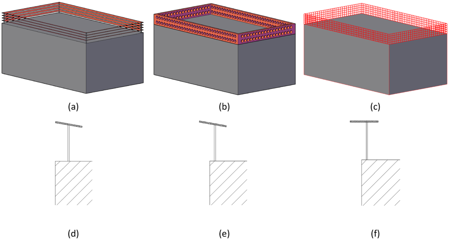
View of parapets with various configurations (h = 0.8 m): (a) slatted fence, (b) porous (circular hole), (c) screen mesh, (d) inclined spoiler, (e) overhanging inclined spoiler, and (f) overhanging horizontal spoiler.
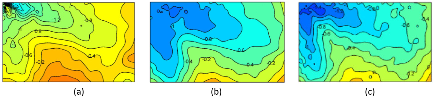
The mean wind pressure distributions in the 315° wind direction for several geometric shapes are provided in Figure 15. Results show that all of parapets exhibit the effect in alleviating the mean corner suction, especially the slatted fence achieving a reduction of 70% in contrast to the case of no parapet. It should be noted that the wind pressure distribution pattern is altered for the slatted fence due to the disturbing effect on the vortices generated by its advantageous configuration. The mitigation of the mean suction at roof happens to the porous parapet; however, the overhanging inclined spoiler does not show the same reduction at the corner as has been seen from the other two.

Mean pressure coefficient contour plots at the wind angle of 315°: (a) slatted fence, (b) porous parapet, and (c) overhanging inclined spoiler.
Figure 16 shows the variation of the worst area-averaged pressure coefficients from all wind directions with tributary areas. As expected in Figure 15, the slatted fence still has advantages of eliminating the worst wind suction occurring at the corner over the other five types of parapets. The porous parapet is beneficial to mitigate the worst suction. It was found that the screen mesh shows similar influence on the negative peak wind pressure to the solid parapet, but performs better in controlling the positive wind pressure than the latter. The spoilers are not as effective as the perimetric parapets, regardless of the overhanging length and slope, which was not consistent with the findings in Kopp et al. (2005c). This discrepancy needs further investigations.

Worst pressure coefficients at corners from all the wind directions for parapets of various configurations.
Power spectral density of typical taps on the roof
To fully assess the effect of parapets on the PSD, three typical taps in three regions (corner, edge, and interior regions) were chosen (see Figure 1(b)) for the following analysis. Figure 17 shows a comparison of the fluctuating pressure PSDs at these taps for the models with and without the 0.8 m perimetric parapets in the case of 315° wind azimuth. The parapets acted as a low-pass filter, very similar to the effect of area averaging. The high-frequency energy is usually absorbed when the air flows around the building and the wind pressures acting on roofs become more stable and even. Hence, it indicates that the installation of parapets is beneficial to eliminate the high-frequency fluctuations and make the air flow steady, which also verifies the uniformly distributed wind pressures on roofs in the presence of solid perimetric parapets as mentioned in section “Perimetric parapets of varying heights.”

PSDs of wind pressure time histories at three taps on the models with and without a 0.8 m parapet for 315° wind azimuth: (a) Tap 1, (b) Tap 2, and (c) Tap 3.
Conclusion
This study evaluated the wind loads on a flat-roofed low-rise building with various parapets based upon a series of wind tunnel tests. The conclusions are summarized as follows:
The spatially averaged wind pressures are less non-Gaussian as compared with the single-tap wind pressure time histories. The area-averaging effect is apparent in lowering the high-frequency end of the wind pressure spectra and consequently weakens the fluctuating wind pressures acting on the roof.
The presence of parapets is also capable of reducing the high-frequency contents of the wind flow and stabilizes the wind effects on the roof.
The wind effects on the roof show some dependence on the selection of the parapet height. It was found that although a high perimeteric parapet (h/H > 0.01) leads to a reduction in the local roof corner suction, it increases wind uplift force acting on the entire roof. . On the contrary, the local worst corner suction was found to decrease with increasing parapet heights in the case of h/H being less than 0.01. When h/H is more than 0.15, the local corner pressures do not change with the parapet height.
The comparison between the experimental results and the current code shows that the codified values for the positive pressures are not conservative, as stated in Kopp et al. (2005a).
Compared to the perimetric solid parapets, those with the raised corners and bottom-slotted corners are more effective in reducing the worst corner suctions. On the contrary, the presence of isolated parapets and those with top-slotted corners is capable of increasing local corner suction.
The slatted fences and porous parapets perform well in mitigating the wind load near the corner. The spoilers do not perform better than the continuous parapets in this study, which was not consistent with the findings in the existing literature. This discrepancy needs further investigations in the future.
Footnotes
Declaration of Conflicting Interests
The author(s) declared no potential conflicts of interest with respect to the research, authorship, and/or publication of this article.
Funding
The author(s) disclosed receipt of the following financial support for the research, authorship, and/or publication of this article: This project is jointly supported by the Ministry of Science and Technology of China (grant no. SLDRCE14-B-09) and Chinese National Natural Science Foundation (nos 51378396 and 51678452), which are gratefully acknowledged.