
Abstract
Drilling and testing core specimens are considered the most common examinations for the reinforced concrete elements. This study brings out new techniques through which the original load-carrying capacity for the cored axially loaded specimens can be restored completely. These techniques consider reshaping the geometry of the circular opening of specimens before repairing to a square or to a rotated square. Moreover, different repairing materials with different compressive and bond strengths to the repaired surface, namely epoxy, grout, and ordinary Portland cement mortars, have been applied. A total of 15 investigated parameters, divided into five groups, in addition to the control specimen were investigated. The results revealed that reshaping the circular opening to a squared one normal to the load application direction, and filling it with epoxy, can completely restore the original capacity of the axially loaded specimens. The finite element model was developed and validated by comparisons with the current experimental results.
Introduction
The assessment of the actual compressive strength of the existing reinforced concrete structures is an important topic. Core drilling, the most common test among the non-destructive tests, is usually used to evaluate the actual compressive strength of the existing reinforced concrete structures. It is essential to assess the safety of a building as well as to evaluate the results obtained with other non-destructive testing techniques. Cutting a circular hole into the concrete in a structural member to extract a cylindrical concrete sample is the common technique in performing the core test. The extracted samples are used to determine different concrete properties by means of laboratory tests as compressive and split-cylinder tests for strength evaluation or carbonation measurements from phenolphthalein test. Concrete strength determination by drilling specimens was studied in several works (Bartlett and Mac, 1994a and 1994b; Bungey, 1979). Although the core test method consists of expensive and time-consuming operations, it gives reliable and useful results. However, the test results are affected by a number of factors, such as height-to-diameter ratio, direction of drilling, presence of reinforcement steel bars in the specimen, strength grade of concrete, as well as moisture condition of the core specimens. More than 500 cores were prepared and tested in addition to the tremendous number of concrete cubes and cylinders by Khoury et al. (2014) in order to investigate the parameters affecting the test. The results indicated that the core strength reduced with the increase in aspect ratio, the reduction in the core diameter, the presence of reinforcing steel, the incorporation of gravel in concrete, the increase in the core moisture content, the drilling perpendicular to casting direction, and the reduction in concrete strength. Small diameter cores were used to determine concrete strength by Bungey (1979), in which 44-mm-diameter cores were cut and tested to determine the concrete strength. The results showed that the core strength was affected by both specimen size and aggregate size. Consequently, conversion to the corresponding cube strength could be achieved with taking into consideration the influence of the pervious factors.
Core drilling for the reinforced concrete beams is usually preferable, especially if it is completely cut within the tension zone (avoiding cutting the reinforcement) compared to that may be cut in axially loaded columns. Mansur et al. (1999) investigated experimentally the influence of core cutting in the tension zone of a reinforced concrete beam subjected to bending. The study concluded that the ultimate moment capacity of the reinforced concrete beam was not affected by the presence of an opening as long as the minimum depth of the compression chord was greater than or equal to the depth of the ultimate compressive stress block. Moreover, filling the opening (created for the determination of in place concrete strength) by non-shrink grout was not adequate to restore the original response.
In spite of the drawbacks of core drilling in the columns that is reflected as a reduction in the load-carrying capacity of cored elements, taking cores from the columns is not often avoidable. In this regard, few studies have been conducted. Zhulei et al. (2010) conducted an experimental study to investigate the influence of core cutting on the axial compression capacity. The study concluded that the axial compression capacity of the reinforced concrete columns after core drilling was reduced from 5.63% to 22.14%, while the ultimate displacement decreased from 1.88% to 26.14%. That study showed that the reduction in the column capacity could be limited to 4% by repairing the hole with slight-expansion high-strength concrete. An experimental investigation was carried out by Campione et al. (2010) about the application of the over-coring technique in the reinforced concrete structures. The study also evaluated the load-carrying capacity of the drilled members after the over-coring tests. The investigation showed reductions in the range between 6% and 20%. Campione and Minafò (2011) performed an experimental investigation on the compressive behavior of bottle-shaped struts and members with openings by testing 20 specimens in both reinforced and plain concrete. Eight elements with circular core drilled openings were among the investigated members. Reductions in the load-carrying capacity, such as 32% for plain concrete specimens and 40% for the reinforced concrete columns, were recorded. The study proposed an extended version of the Sahoo et al.’s (2009) model to evaluate the ultimate capacity of drilled specimens.
An analytical study was conducted to investigate the load-carrying capacity of axially loaded reinforced concrete members with circular openings (Giovanni, 2012). The analysis provided an analytical model able to predict the load-carrying capacity of the reinforced concrete columns with core holes. Although the core drilling test is common for specialists in the field of concrete technology and is widespread all over the world, its impact on the load-carrying capacity as well as the efficiency of the repairing technique are not completely understood (Zhulei et al., 2010). McGinnis and Pessiki (2015) studied (1) the swelling of the concrete around the core hole caused by the exposure to water used during the drilling process, (2) changes in the measured deformations caused by the relief of differential shrinkage stresses, and (3) the steel reinforcement in close proximity to a core hole. That study addressed each of these factors through analytical and numerical techniques that adjust core drilled method calculated stresses. Campione et al. (2015) provided an experimental study on the reinforced concrete cored columns to monitor the effects induced by circular openings. The tested parameters were the concrete strength, core diameter, and repairing process. The results revealed that the analytical predictions made by strut-and-tie model showed good agreement with the experimental data.
In the light of the above, this study is directed to develop new techniques for the restoration of the load-carrying capacity of axially loaded cored (laboratory-scale) specimens.
Research significance
In reviewing the published literature and according to the best knowledge of the authors, the efficiency of the restoration to full capacity of cored elements has not yet been investigated. Hence, this study is directed to investigate the influence of core drilling on axially loaded specimens and the restoration of its capacity. Reshaping the circular opening of the core (to square or rotated square in shape), the materials to be used in core repairing as well as methodologies and techniques followed by the restoration of the specimen’s capacity are the investigated parameters.
Experimental program
Specimens’ description
A total of 32 short reinforced concrete identical column specimens with 100 mm × 100 mm × 500 mm dimensions and reinforced with four longitudinal plain bars of a diameter of 8 mm and horizontal stirrups of the same steel were used for the longitudinal reinforcement at a spacing of 80 mm reduced to 50 mm at the end as depicted in Figure 1(a). Specimens were cast and cured up to the time of the core drilling at the 28-day age. The experimental program for all investigated parameters and techniques is tabulated in Table 1. The conducted axially loaded specimens included control column specimens without core openings (C) as a reference. Then the 15 investigated parameters were classified into five groups. Group 1 (G1) was unrepaired cored specimens with different geometry in order to interpret the stress flow around the opening and comparisons. In G1, the reinforced concrete column specimens were cored with circular openings of 40-mm diameter at the mid height of the columns (CCO). Moreover, the cored concrete column specimens were reshaped by sculpture to a square opening of 40-mm side length for the all depth of the specimen (CSO), and the reinforced concrete column specimens were cored and reshaped by the same matter to a rotated square opening of 40-mm side length (CSRO), as shown in Figure 1(b). From G2 to G5, the checked parameters were the repairing materials and techniques where filling the CCO, CSO, and the CSRO specimens with bonded epoxy (BE) mortar, unbonded epoxy (UBE) mortar, bonded grout (BG) mortar and bonded cement mortar (BCM). “Bonded” means that the used repairing mortar was allowed to adhere to the internal surface of the specimen. In case of using epoxy mortar, two parameters were checked. The first parameter was allowing the mortar to bond to the opening internal surface. The second one was to check the using of this high-strength mortar (epoxy mortar) without adhesion. A very thin plastic sheet was used for preparing the UBE specimen. Two identical column specimens were tested for each specified parameter, and the average was considered. After core drilling and repairing the different opening shapes, the specimens were moist cured for another 28 days and then the compression axially loaded test was started. The repaired columns with cement mortar, grout mortar, and epoxy mortar were cast and tested. The load-carrying capacity, the strain distribution around the openings in case of repaired and unrepaired specimens, as well as the failure modes were the investigated properties.
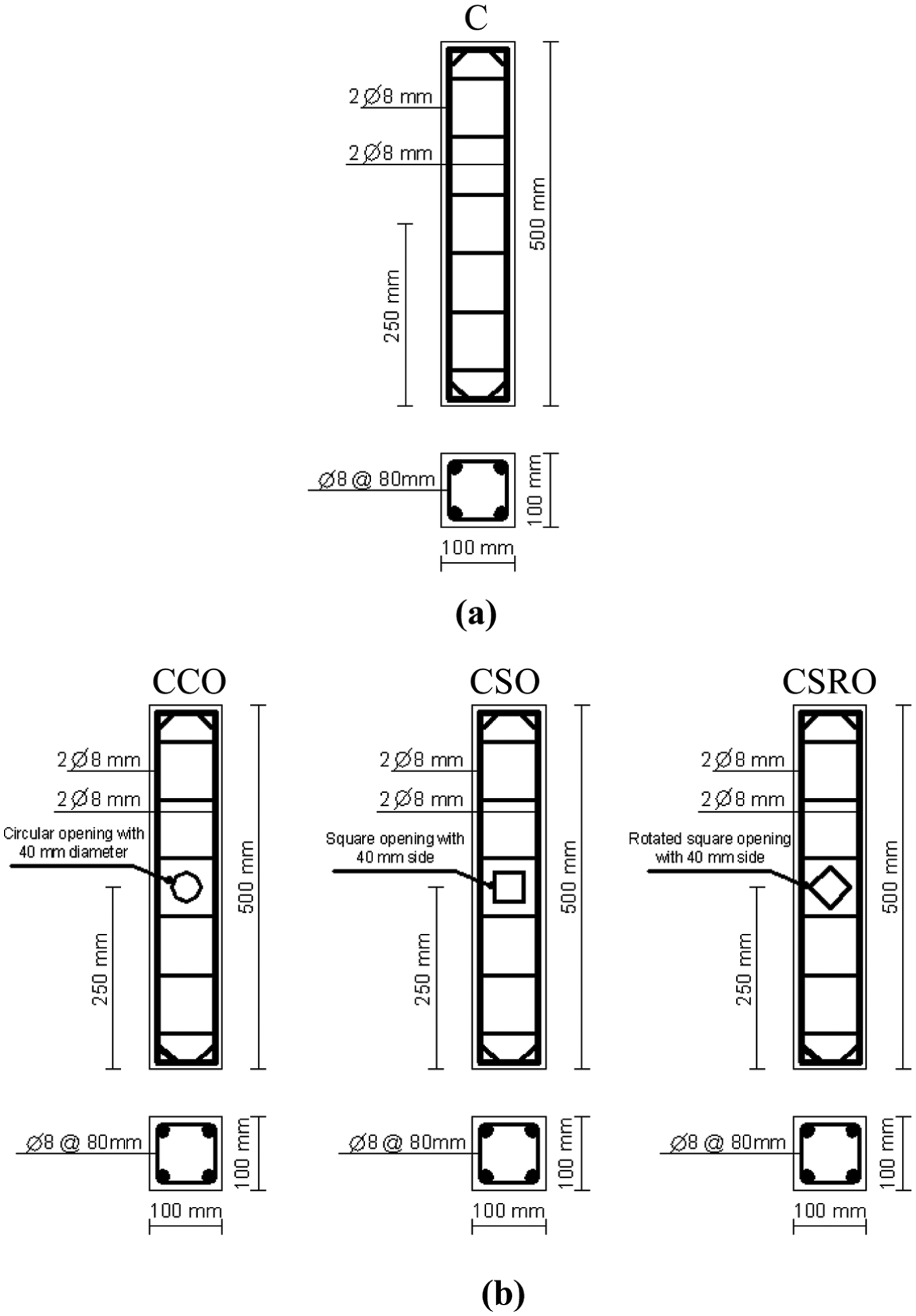
Details of the conducted columns: (a) reference specimen and (b) the parametric study specimens cored with circular opening CCO, cored with circular opening then reshaped by sawing to square opening CSO, and reshaped by sawing to rotated square opening CSRO.
Summary of investigated parameters.
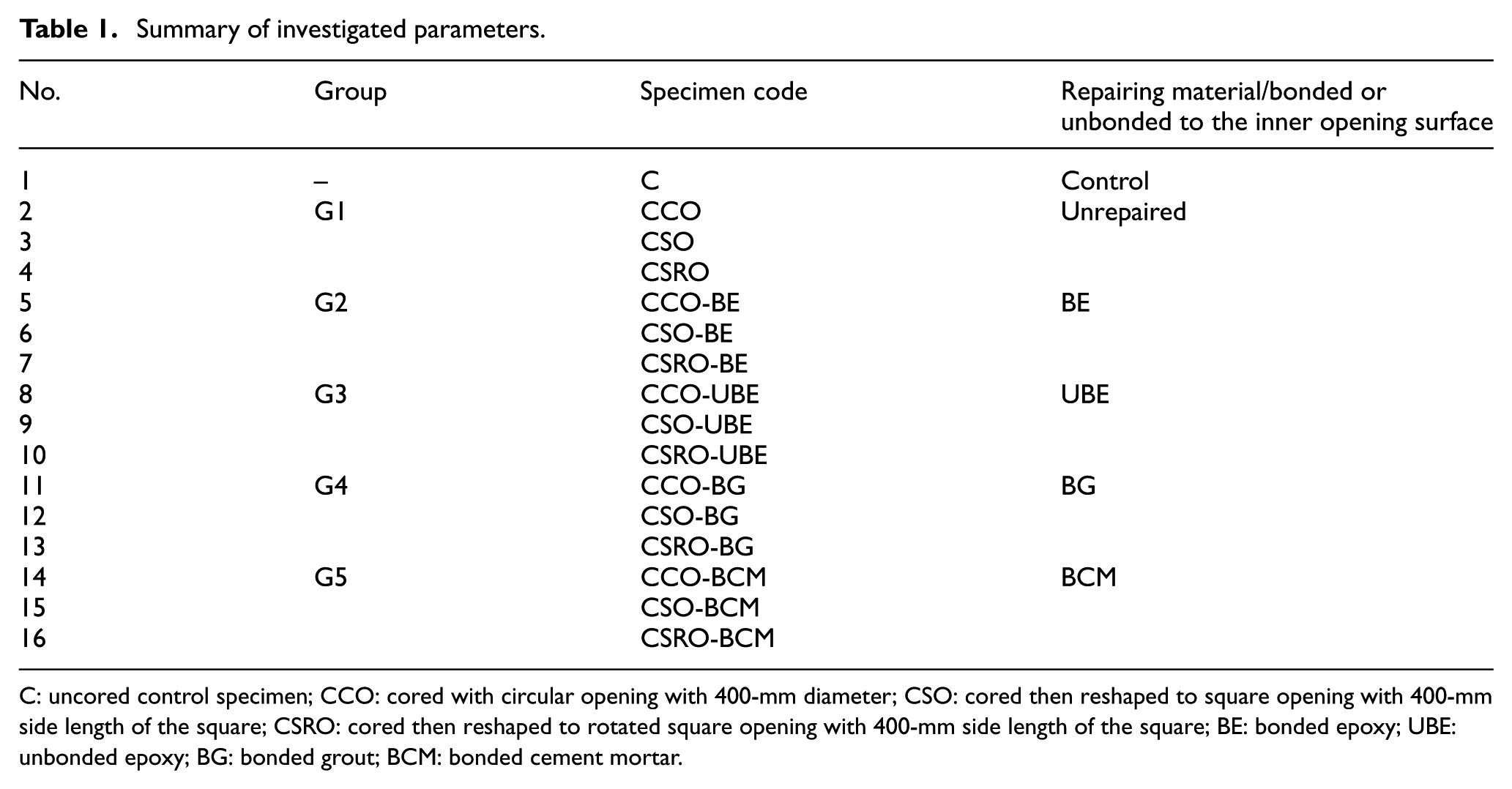
C: uncored control specimen; CCO: cored with circular opening with 400-mm diameter; CSO: cored then reshaped to square opening with 400-mm side length of the square; CSRO: cored then reshaped to rotated square opening with 400-mm side length of the square; BE: bonded epoxy; UBE: unbonded epoxy; BG: bonded grout; BCM: bonded cement mortar.
Test setup and instrumentations
In order to investigate the effect of the core opening shape as well as the methodology being implemented to repair circular openings before and after reshaping, electrical strain gauges were arranged, as shown in Figure 2. The used electrical strain gauges were of 50-mm gage length. Its gage factor was 2.14% ± 1.0%. The gage resistance at 24°C and 50% relative humidity (RH) was 119.6 ± 0.4 Ω as given by the supplier. Strain gauges were attached to the concrete surface with a special glue, namely cyanoacrylic glue. Before attaching the used electrical strain gauges, the concrete surface was smoothed with very fine sand paper, de-oiled with solvents; the solvent traces were removed and the strain gauge was glued immediately. All specimens were tested up to failure under uniaxial centric load. A hydraulic universal testing machine of 300 kN capacity was used to apply the vertical load to the tested specimens. The testing machine is computer controlled and works under either load or displacement control. The test was executed under displacement control as 0.5 mm/min. A rigid steel cap with a thickness of 15 mm was used to protect the two ends of the columns from crushing during testing. These caps were attached to the specimens with gypsum paste. Testing loads and all strain readings were recorded automatically by the data acquisition system attached to the testing machine.
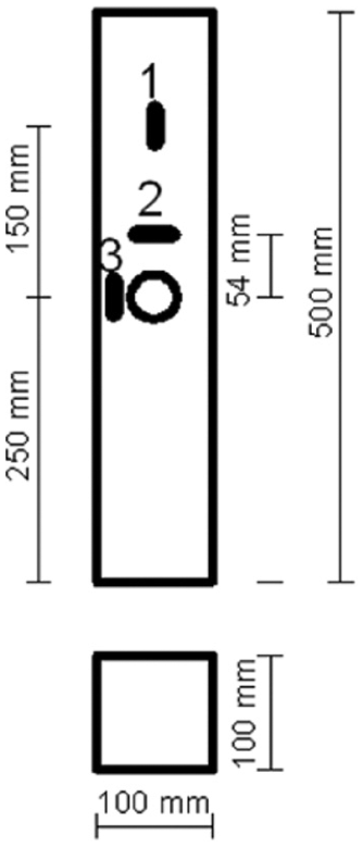
Locations at which the strain gauges were arranged during the test.
Material properties
Concrete
Cement: Ordinary Portland cement of grade CEM-I-42.5N was used in this investigation; 80 and 270 min were the initial and final setting times, respectively. The used cement conforms to the requirements of EN196-1 (2005). Fine aggregate: Medium well-graded sand of fineness modulus 2.79 was used. Coarse aggregate: Natural well-graded gravel aggregates of 10 mm maximum nominal size were used. Fine and coarse aggregates conformed to the requirements of the Egyptian Standard Specifications (2002) (ESS 1101). Water: Clean water from the water supplier tap was used in both the mixing and curing processes. Concrete mix: An ordinary Portland cement concrete mix consisting of 1:1.75:3.4:0.5 by weight for cement:fine aggregate:coarse aggregate:water, respectively, was used to cast the conducted column specimens; 150-mm slump was recorded for the fresh concrete mix. Moreover, 11, 25, and 32 MPa compressive strength were recorded for the concrete mix measured using concrete cubes of 100 mm × 100 mm × 100 mm at 3, 7, and 28 days, respectively. The relationship between compressive stress and strain for cylinder specimens of 100 mm × 150 mm is shown in Figure 3.
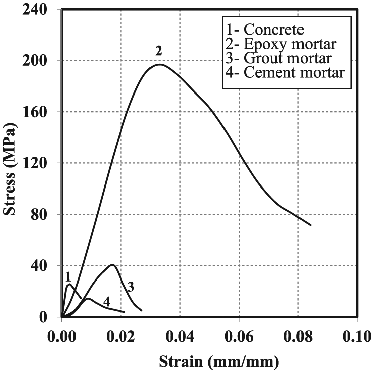
Stress–strain relationship for the concrete used in casting of executed column specimens and repairing materials.
Steel reinforcing bars
Normal mild steel bars of 8-mm nominal diameter were used as the reinforcement for both the longitudinal and lateral reinforcements in the columns. The values of the yield and ultimate strengths are 249 and 367 MPa, respectively.
Repairing materials
Epoxy mortar: An epoxy mortar composed of 1:12 hardener:filler, respectively, was used to repair the circular and reshaped openings of the specimens of group 2; 197 and 2.85 MPa were the compressive strength and the bond strength to the repaired concrete, evaluated by a pull off test according to EN 1542 (1999), measured at the age of 14 days, respectively. The bond strength to the concrete surface was close to that of the tensile strength of the concrete (2.8 MPa) and that agreed well with the mode of the fracture pattern shown in Figure 4 by concrete fracturing. Figure 3 shows the stress–strain relationship for the epoxy mortar. Grout mortar: Ready grout mortar was used to repair the specimens of group 4. It had 30 and 43 MPa compressive strengths at 1 and 14 days, respectively. Whereas the bending strength and the bond strength to the repaired concrete, measured by a pull off test according to EN 1542 (1999), were 11 and 1.66 MPa, respectively. The compressive stress versus strain curve for grout mortar is shown in Figure 3. Ordinary Portland cement mortar: Ordinary Portland cement mortar, composed of 1:3:0.34 cement:sand:water by weight, was used as a repairing material for the specimens of group 5. The used mortar had 14.8 MPa as compressive strength after 2 weeks, as well as 0.45 MPa as bond strength to the repaired concrete measured by the pull off test according to EN 1542 (1999). The compressive stress–strain relationship for the used cement mortar is presented in Figure 3.
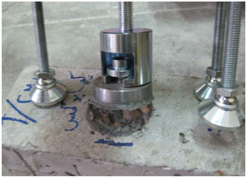
Fracture surface along with using epoxy mortar by pull off test (EN 1542, 1999).
Experimental results and discussion
Strain distribution around the unrepaired specimen with circular openings (CCO)
Strain distribution outside the disturbed area (strain 1) as well as strains inside the disturbed region and arranged in the horizontal and vertical directions (locations 2 and 3) were investigated for the column specimens with circular hole (CCO) of group 1. The measured strains are shown in Figure 5. At location 1, the values of strains are dependent only on the applied load for the tested material, whereas at location 2 the measured values of strain pointed out tensile strain values because of the horizontal bursting tensile force due to the flow of stresses around the hole which agree with that presented by Minafò (2012). The measured strain values at location 3 indicated the excess of stress due to the loss of cross section as a consequence of the existing opening.
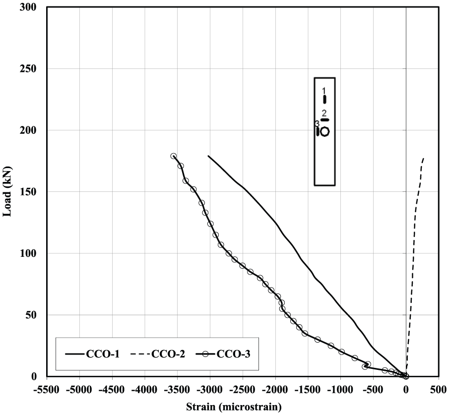
Strain distributions around the circular hole for unrepaired CCO specimen.
Strain distribution around the repaired openings of specimens from G2 to G5
The influence of both the repairing material type and techniques was studied through studying the distribution of strains around the repaired zones. Strains at locations 1–3 were measured and are plotted in Figures 6 to 9. Figure 6 presents the relationship between load and strains for the columns repaired with BE (G2). Compared to the unrepaired opening (CCO), using epoxy to fill the opening influences the strain distribution around the repaired hole. For location 1, the strain values increased with the applied load until the column failure for all the tested column specimens CCO, CSO, and CSRO. Whereas at location 2 the resulting horizontal tensile strains were influenced by the adopted repairing epoxy material due to the good bond between both materials (evaluated by the pull off test). That bond force resulted in a closing force opposite to the bursting tensile, one which consequently increases the load-carrying capacity as could be noticed in Figure 6. On the other hand, strains at location 3 were relatively lower for sections that were transformed to square ones before repairing. That may be due to the mechanism of stress transfer to the repaired material which was noticed to change when altering the circular opening to a squared one normal to the load direction. That also may be due to the absence of the arch effect related to the high-strength circular shape of the repaired methodology. The relatively high strain values reached when using epoxy as a repairing material could also be explained using the well-known strut-and-tie model (Minafò, 2012).
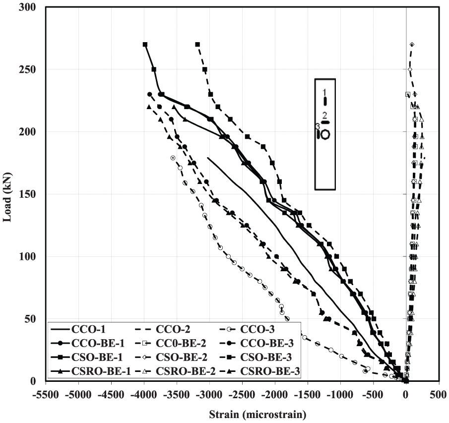
Strain distributions around the hole repaired with bonded epoxy mortar.
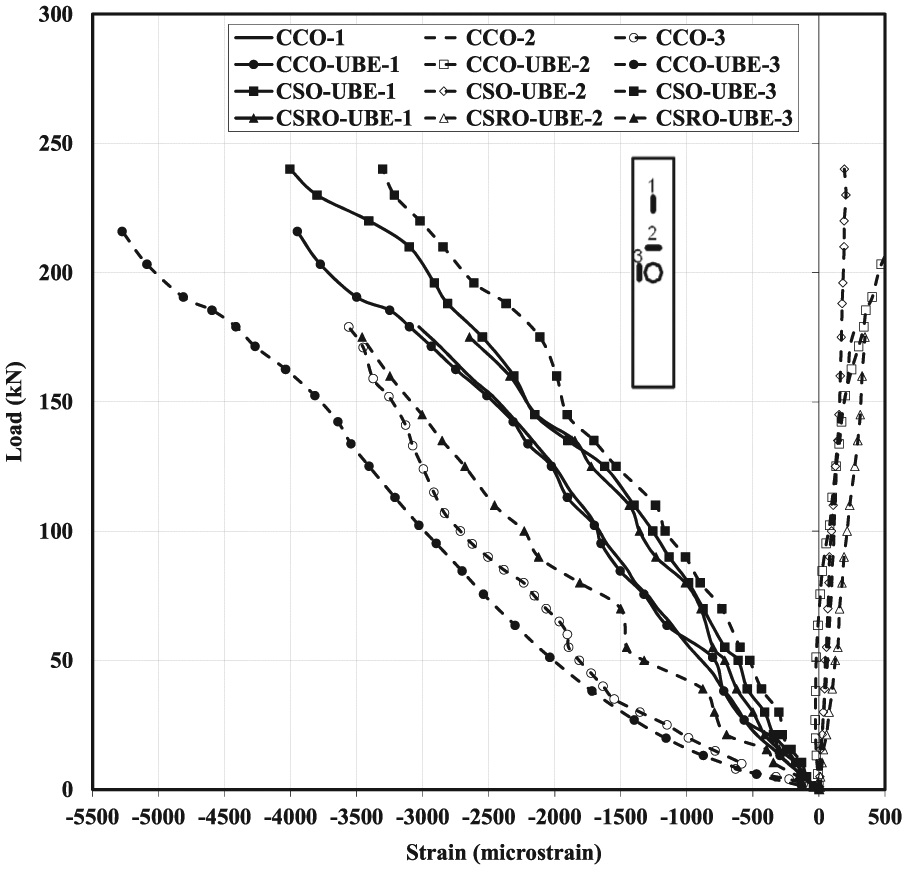
Strain distributions around the hole repaired with unbonded epoxy mortar.
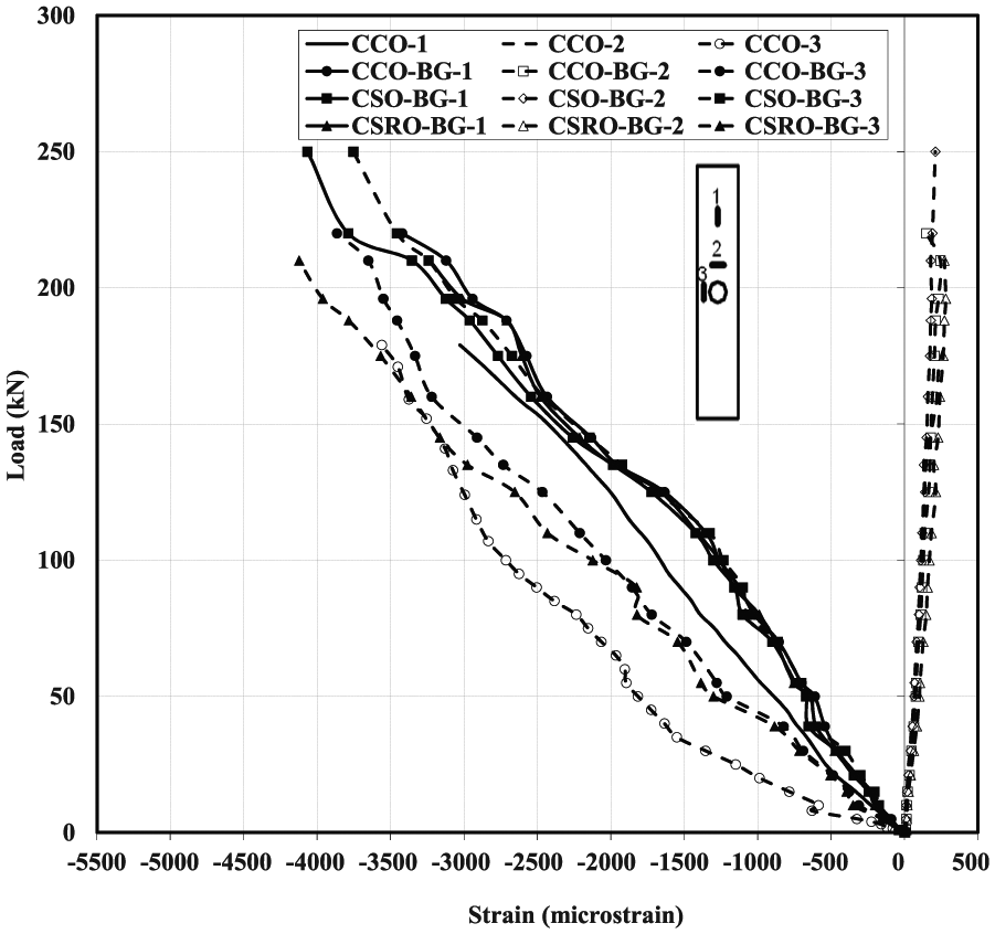
Strain distributions around the circular hole repaired with bonded grout mortar.
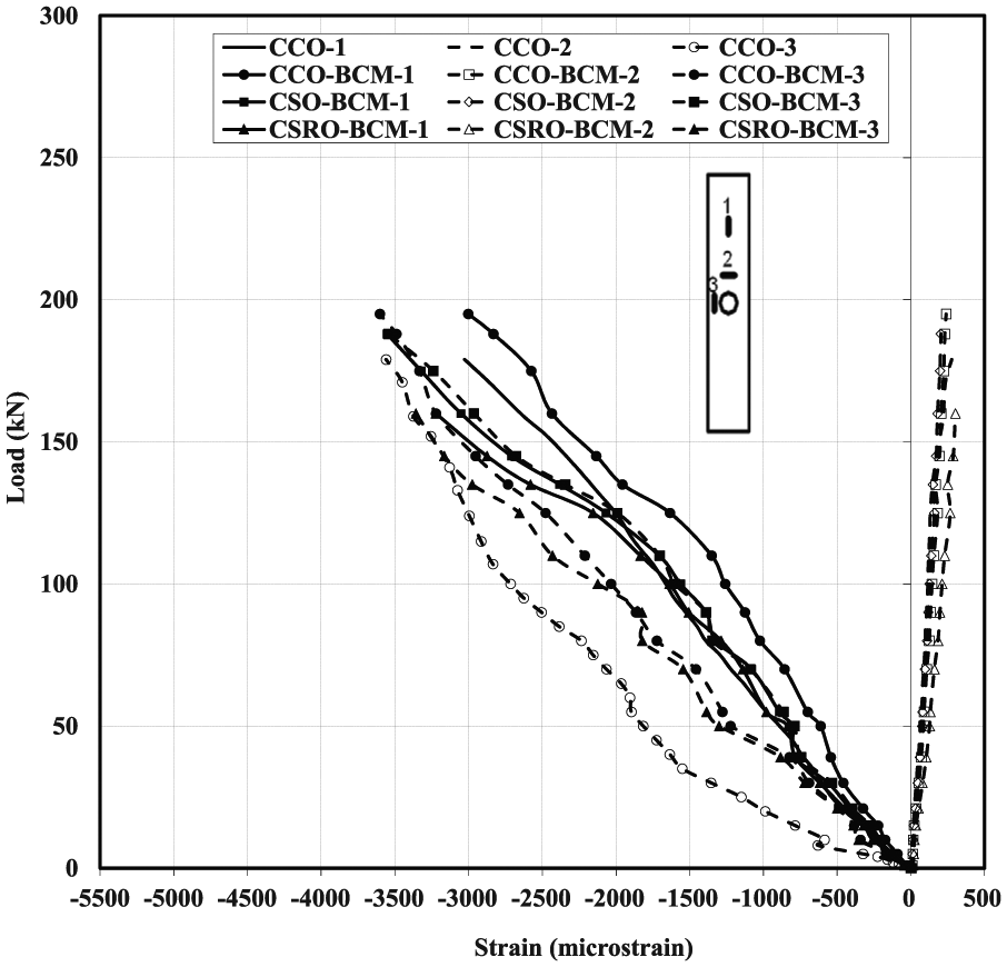
Strain distributions around the hole repaired with bonded cement mortar.
For the unbonded technique as a repairing methodology (G3), it could be simply noticed that through the measured strain values, the reduction in the load-carrying capacity for the investigated column specimens is due to the absence of the phenomena of the closing force as a result of the absence of bond between the repaired surface and the repairing material, as shown in Figure 7. For other repairing materials, including cement mortar and grout (G4 and G5), the same trend was recorded. The measured strain values are presented in Figures 8 and 9. It could be simply noticed that due to the relatively low bond strength between the repairing material of cement mortar and grout to the repaired surface, compared to that of epoxy mortar, the generated closing force at the locations of the repaired openings, the load-carrying capacities, were somewhat lower compared to those repaired with epoxy due to the relatively low closing force. The closer the strain value at locations 1 and 3, in addition to the lower the strain value at location 2, the more effective the proposed repairing technique. For all the test parameters, specimen CSO recorded the lowest values of strain at location 2, which reflect an indication to a uniform distribution of stress instead of a stress concentration.
Cracking pattern
The process of failure of the tested column specimens repaired with grout mortar (CCO-BG) is presented in Figure 10(a) and (b). First, vertical cracks were formed perpendicular to the bursting horizontal force. With the excess of the applied load, the formed cracks grew to wider widths, finally, and due to the concentration of the applied stress around the repaired area, a brittle failure was recorded. The recorded crack pattern agreed with the results of Campione et al. (2015). That sequence can explain the arch effect phenomena associated with repairing the circular openings with high-strength mortars. On repairing specimens with low bond strength material like CCO-BCM, first de-bonding at the contact surface was observed accompanied by a large crack width which led to failure, as shown in Figure 10(c). Repaired specimens with the rotated square technique (CSRO-BCM) yielded the lowest failure loads due to stress concentration and wide cracks (see Figure 10(d)).
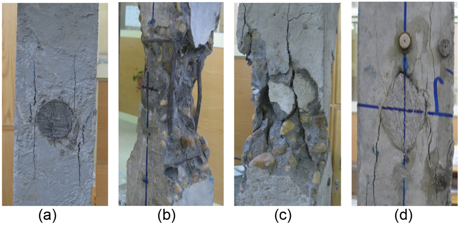
Cracking sequence for repaired tested columns: (a) specimen CCO-BG, first vertical cracks; (b) specimen CCO-BG, at failure; (c) specimen CCO-BCM, de-bonding; and (d) specimen CSRO-BCM, stress concentration.
Load-carrying capacity
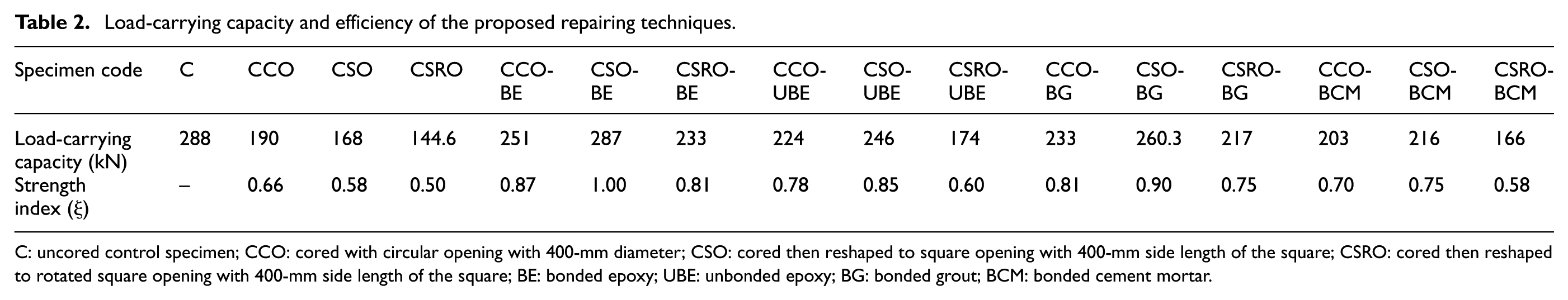
The results of the tested columns are tabulated in Table 2. The load capacity of control column (C) was 288 kN. The load column capacities for unrepaired column specimens (G1) having a circular opening, a squared opening, and rotated square opening were 190, 168, and 144.6 kN, respectively. It is clear that the existence of an opening of any shape reduced the capacity of the conducted column specimen which is a logical issue (Campione et al., 2015; Minafò, 2012).
Load-carrying capacity and efficiency of the proposed repairing techniques.
C: uncored control specimen; CCO: cored with circular opening with 400-mm diameter; CSO: cored then reshaped to square opening with 400-mm side length of the square; CSRO: cored then reshaped to rotated square opening with 400-mm side length of the square; BE: bonded epoxy; UBE: unbonded epoxy; BG: bonded grout; BCM: bonded cement mortar.
Whereas when using BE (G2) to fill the core locations or the transformed core opening, the measured capacities for the tested column specimens were 251, 287, and 233 kN for CCO, CSO, and CSRO, respectively. To investigate the influence of bond strength between the repaired surface and the repairing materials and to show which role they play in restoring the load-carrying capacity, unbonded repaired column specimens with epoxy (G3) material were investigated. The load-carrying capacities were 224, 246, and 174 kN for CCO, CSO, and CSRO, respectively. Comparing the results of G2 and G3 gave an indication of the importance of the bond strength between the repaired surface and the repairing material in restoring the load column capacity.
On the other hand, when BG was used as a repairing material (G4), the load-carrying capacity values were 233, 260.3, and 217 kN for CCO, CSO, and CSRO, respectively. In view of the current results of G3 and G4, it could be concluded that using high compressive strength repairing mortar is not a sufficient factor in capacity restoration but also the bonding at the contact surface is vital. For series in which BCM (G5) was used as a repairing material, the load-carrying capacity values were 203, 216, and 166 kN for CCO, CSO, and CSRO, respectively. That means, using Portland cement mortar to fill the circular openings enhances the load-carrying capacity compared to the G1 results. It could also be noticed that the repairing technique of G5 recorded the lowest results among the proposed techniques in terms of load capacity.
Efficiency of the proposed repairing techniques
In order to evaluate the efficiency of the proposed different repairing techniques, a simplified analysis procedure using the strength index, ξ, previously proposed by Taher (2005) and Atta and Taman (2015) was used. ξ is an adaptation factor equal to the value of the failure load of the strengthened specimens to the failure load of the control uncored specimen. Table 2 lists the estimated values of the strength index ξ for the various repairing techniques of the tested specimens. It was noted that reshaping the cored specimen to a squared opening and using high compressive strength and bond repairing material (epoxy) in addition to transforming the circular opening to a squared one (CSO-BE) restored the full capacity of the tested specimen.
Finite element model
Finite element type and mesh
Concerning concrete axially loaded columns and the materials used in core repairing, three-dimensional eight-node linear brick reduced integration solid elements, the so-called C3D8R (Dassault Systèmes, 2008), were used. However, the Drucker–Prager yield criterion model was adopted for concrete after the linear response; see Ellobody and Young (2006), and Hassanein et al. (2013). This model is used to define the yield surface and the flow potential parameters for the materials subjected to triaxial compressive stresses. To define the yield stage of the concrete and the repairing materials, two parameters (Drucker–Prager and Drucker–Prager hardening) are used. The linear Drucker–Prager model is used with associated flow and the isotropic rule. The angle of friction (β) and the ratio of flow stress in triaxial tension to that in compression (K) are taken as 20° and 0.8, respectively, as used by Hassanein et al. (2013). The Drucker–Prager hardening was defined using the full stress–strain curve of the concrete and the repairing materials as given in Figure 3. The reinforcing re-bars were modeled as two-node three-dimensional linear truss elements, T3D2. The steel reinforcement material was modeled as the von Mises material with isotropic hardening. Also, the bilinear elastic–plastic stress–strain curve with linear strain hardening was used to simulate the steel reinforcement. To simulate the interaction between the concrete column and the materials used in core repairing, a surface-based interaction with a contact pressure-overclosure model in the normal direction and a Coulomb friction model in the directions tangential to the surface were used for unbonded material and BCM. In order to construct contact between two surfaces, the slave and master surfaces must be chosen successfully. Generally, if a smaller surface contacts a larger surface, the best is to choose the smaller surface as the slave surface. Herein, the repairing material surface was chosen as the slave surface, whereas the concrete column surface was chosen as the master surface. On the other hand, core repairing materials were connected to the concrete column by the “Tie” constraint, available in ABAQUS (Dassault Systèmes, 2008), to simulate the interaction of the bonded repairing material. A mesh of an approximate global size of 15 mm was used in the current modeling for the columns and the repairing materials (see Figure 11). The mesh was chosen to be finer near the opening of the core at the strain measurements.
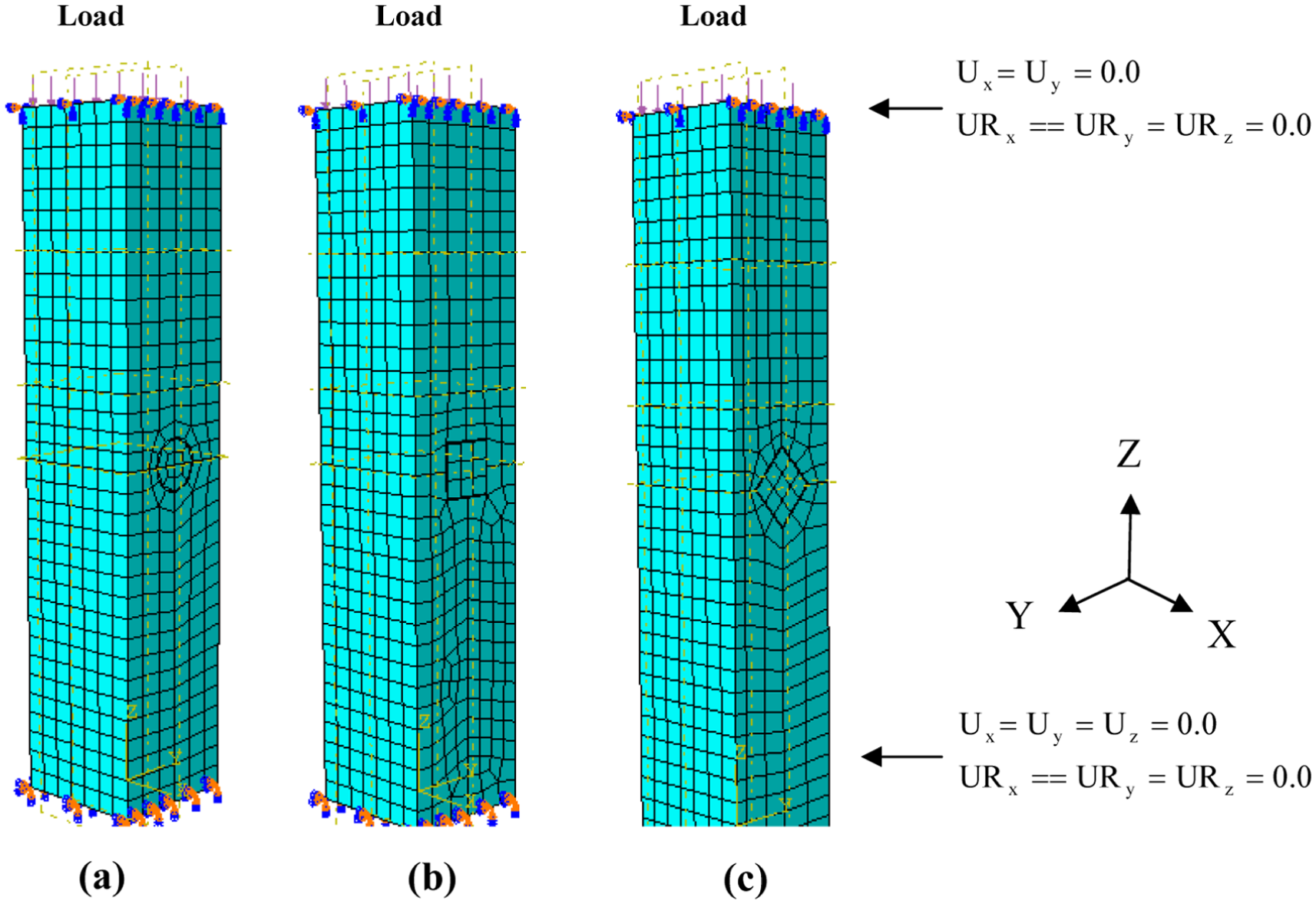
Typical finite element mesh, boundary conditions, and applied load of specimens with repaired materials: (a) circular, (c) square, and (b) rotated square.
Boundary conditions and load application
The concrete axially loaded columns considered herein had fixed ends, but a displacement at the loaded end (the upper level of the column) in the direction of the applied load was allowed. Pressure load was applied statically at the top of the column using the displacement control. The load was applied incrementally using the modified Riks method available in the ABAQUS library. In the Riks method, the load is applied proportionally in several load increments. In each load increment, the equilibrium condition is achieved by numerical iterative scheme. This method is often used in static analysis and shows to be efficient for nonlinear analysis. The nonlinear geometry parameter (*NLGEOM) was included to deal with the large displacement analysis. The load application for a typical column is presented in Figure 11.
Comparison between the FE model and the experimental results
The FE model (FEM) developed was used to predict the behavior of core drilling on axially loaded columns tested in this article. The ultimate axial loads of the specimens obtained from the FE analyses are compared with test data in Table 3. The FEM yields good predictions of the ultimate loads of axially loaded columns. The mean value of PEF/PEXP is 0.95 with a coefficient of a variation of 0.042. Also, the load–strain relationships (S1, S2, and S3) measured in the experimental investigation are compared with FE results. Figure 12 shows a comparison of the current FE and experimental results which provides a sample of the results for the sake of the clearness of the presentation. It can be observed that the FEM predicts well the complete load–strain curves for these tested specimens. On the other hand, Figure 13(a) presents the contour lines for the stress distribution for specimen CCO from the FEM. The stress concentration and its maximum values for this specimen (CCO) confirmed the arch effect and agreed with that observed experimentally and with that obtained by Minafò (2012). In case of using high-strength mortar without reshaping the cored specimen (CCO-BE), as seen in Figure 13(b), the stress concentration around the opening and the arch effect is still dominant. Figure 13(c) shows uniform stress distribution inside and around the repaired opening of the CSO-BE specimen. This uniform stress distribution reflects the efficiency of this repairing technique. Due to the change in material properties, the repairing material of this specimen (CSO-BE) also recorded slightly lower stress than the surrounding concrete stress. As can be seen, in general the current FEM can be used to describe the behavior of core drilling on axially loaded columns.
FE and experimental ultimate loads of current specimens.
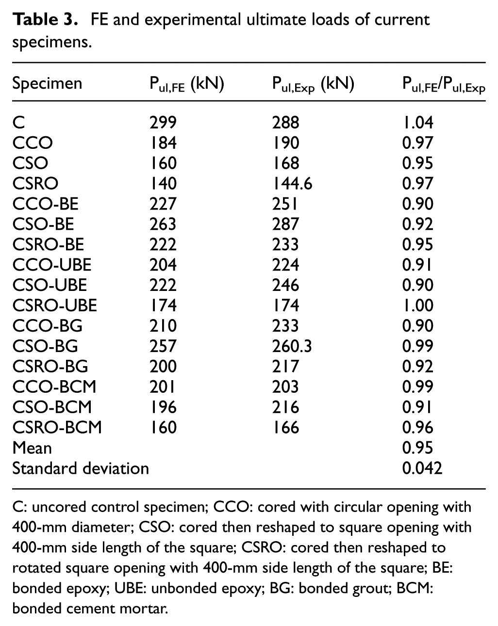
C: uncored control specimen; CCO: cored with circular opening with 400-mm diameter; CSO: cored then reshaped to square opening with 400-mm side length of the square; CSRO: cored then reshaped to rotated square opening with 400-mm side length of the square; BE: bonded epoxy; UBE: unbonded epoxy; BG: bonded grout; BCM: bonded cement mortar.
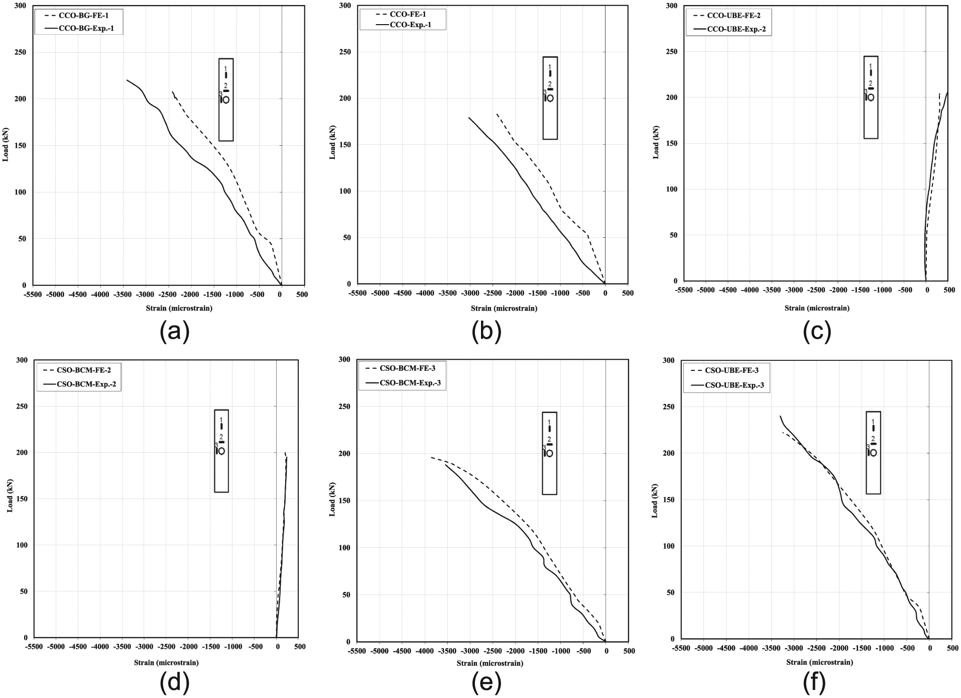
Comparison between finite element and experimental results: (a) specimen CCO-BG-1, (b) specimen CCO-1, (c) specimen CCO-UBE-2, (d) specimen CSO-BCM-2, (e) specimen CSO-BCM-3, and (f) specimen CSO-UBE-3.
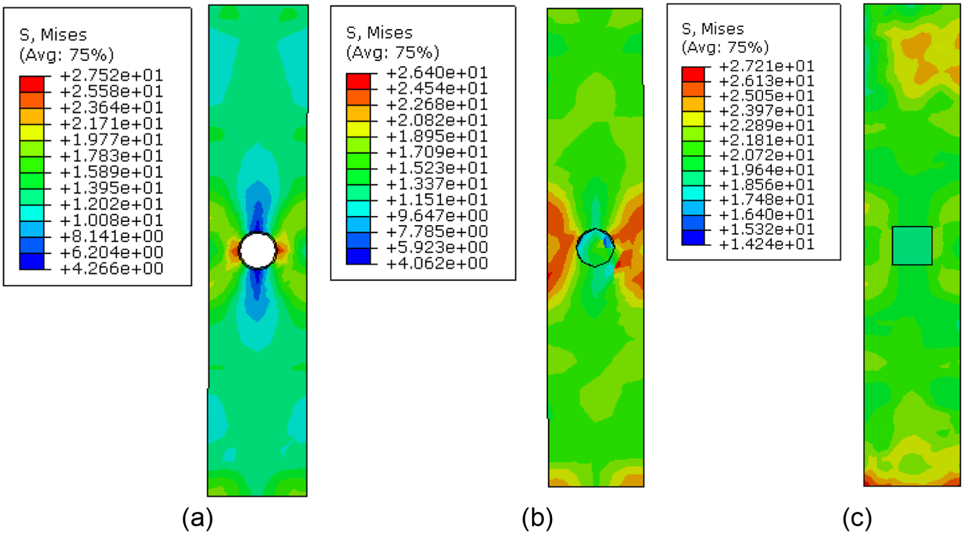
Stress distribution from FE: (a) specimen CCO, (b) specimen CCO-BE, and (c) specimen CSO-BE.
Summary and conclusion
In this article, an experimental program was performed on 32 identical short axially loaded specimens, first cored and then repaired with different repairing techniques. FEM was made for the tested specimens. Based on the results and discussions for the present experimental and numerical work, the following conclusions could be drawn:
The existing of a circular opening that simulates core drilling can remarkably reduce the load-carrying capacity as a result of cross section reduction. Moreover, filling the core opening with repairing material cannot completely restore the original capacity of the cored investigated axially loaded specimens.
Using the traditional method for repairing the circular opening by filling it with grout mortar leads to an 81% restoration of the full load-carrying capacity.
Using a repairing material of relatively high compressive strength as well as good bond strength to the repaired surface (greater than its tensile strength) plays an important role in restoring most of the original load-carrying capacity of the cored axially loaded; 87% of the full load of the axially loaded specimens capacity could be restored by this technique.
The load-carrying capacity of the cored investigated axially loaded specimens could be restored completely by transforming the circular opening to a squared one normal to the load application direction, parallel to using repairing material of relatively high compressive strength and processes good bond to the repaired surface.
The reshaping of the circular opening into a squared one normal to the load application direction and filling it with an epoxy mortar can completely restore the original load-carrying capacity of axially loaded cored investigated axially loaded specimens.
For axially loaded tested specimens, it is recommended to reshape the circular opening to a squared one normal to the load application direction before repairing.
It can be seen that the current FEM gave accurate results compared with the experimental ones.
Finally, it can be recommended in further studies to use FEM in order to generate more parametric variables on full-scale elements to save time, efforts, and cost.
Footnotes
Acknowledgements
The tests were carried out in the Material Properties Laboratory, Faculty of Engineering, Tanta University. The authors are grateful for the skilled technical assistance of the laboratory staff.
Declaration of Conflicting Interests
The author(s) declared no potential conflicts of interest with respect to the research, authorship, and/or publication of this article.
Funding
The author(s) received no financial support for the research, authorship, and/or publication of this article.