



Abstract
The practice of using fiber-reinforced polymer laminates and fabric to repair and strengthen concrete structures is well established. What limits the application of fiber-reinforced polymer materials, especially in flexural strengthening, is the equipment and man power needed for continuous application when retrofits take place over waterways or multilane roadways. A carbon fiber–reinforced polymer rod panel system consisting of 1220-mm (48-in) panels made continuous through a finger joint/splice was developed to overcome these limitations. The system’s performance hinges on whether forces can be transferred from one panel to another. This study investigated the bond characteristics of carbon fiber–reinforced polymer rods, as well as the flexural behavior of concrete members strengthened with carbon fiber–reinforced polymer rod panels, to improve knowledge of the finger joint’s behavior. Bond tests were conducted using double-lap shear specimens on individual rods with both steel and concrete substrates. Further bond tests were performed on small carbon fiber–reinforced polymer rod panels on steel substrate. Flexural tests were carried out under four-point bending on small-scale reinforced concrete beams that were strengthened using continuous carbon fiber–reinforced polymer rod panels and carbon fiber–reinforced polymer rod panels spliced using a finger joint. Case studies of four field applications are presented to provide a better understanding of the system. The new carbon fiber–reinforced polymer rod panels effectively reduce labor and equipment costs for work conducted on bridges with limited access, as they enabled the performance of repair/retrofit operations by a small crew working out of a single work platform.
Introduction
High-performance materials that include advanced composites can have very high strength-to-weight ratios and are suitable for efficient structural repair of deficient members. These materials allow for rapid placement and require minimal labor compared to traditional methods. The use of fiber-reinforced polymer (FRP) laminates and fabrics to repair and strengthen reinforced concrete (RC) structures is well established, with design guidelines in the form of ACI 440.2R-08 (ACI Committee 440, 2008), Technical Report 55 (Concrete Society, 2012), and European fib bulletin 14 (Fédération internationale du béton (fib) Task Group 9.3, 2001). Over the past decade, carbon fiber–reinforced polymer (CFRP) composites have proven to be a cost-effective and successful retrofit method for buildings and bridges. The primary advantages they offer over other materials include their noncorrosive properties, magnetic transparency, high strength, low weight, high durability, and ease of application. Many bridges around the world have been repaired and/or strengthened using CFRP composites, and their use is expected to increase in the future.
Over the past several decades, many studies have examined techniques that are used to repair and retrofit steel and concrete structural elements. The retrofit of structural members, especially in bridges, has become increasingly important because they tend to carry greater loads and higher traffic volumes than they were originally designed for. Applying precured CFRP laminates to structural members is a retrofit method that increases the flexural capacity of flexural members. Yet retrofitting beams in long-span bridges that pass over roadways, waterways, or deep ravines requires significant equipment inputs and considerable labor to maintain laminate continuity over the entire span. When the bridge is located over a roadway with multiple traffic lanes, the retrofit could require lane closure under the entire span, causing prolonged and costly traffic congestion. While carbon fabric sheets can be applied in shorter lengths and overlapped easily to maintain continuity, this is rarely done in the field, as typically two or more layers of fabric would be required to provide the same level of strengthening as the much thicker pultruded laminate.
Few studies have reported on the viability of lap splicing of CFRP plates for concrete beams in order to maintain continuity of the strengthening system (Stallings et al., 2000; Stallings and Porter, 2003). Schnerch and Rizkalla (2008) evaluated the effectiveness of lap splices for composite concrete deck–steel girders, while Dawood et al. (2009) studied lap splices for steel beams. The study by Stallings and Porter (2003) found that splice plate debonding was the predominant failure mode and recommended limiting the nominal shear stresses to be below 15% of the adhesive shear strength. The study by Dawood et al. (2009) on splice lengths and different end geometries for ultra-high modulus (UHM) CFRP laminates found that the typical square plate ended splice plates debonded at 55% of the unstrengthened beam yield load. Due to the limitations of traditional splice plates, Peiris (2011) studied the feasibility of developing a splicing method for CFRP laminates that would let individual workers execute the strengthening process on a single-man lift or scaffolding, thus significantly reducing labor and equipment costs. This research aimed to develop a modular structural strengthening system, and it investigated the bond characteristics between structural steel and UHM CFRP strips and the performance of UHM CFRP strip panels under flexural loading. The length of each UHM CFRP strip panel was 1220 mm (48 in), allowing individual workers to handle and mount sections on to the bottom or sides of girders. Originally developed using UHM CFRP strips for steel beam strengthening, the authors investigated whether adopting a similar system for RC beams is viable. Commercially available CFRP laminates, reinforcing bars and rods, as well as stainless steel wires and rods were considered for producing the strip/rod panels. Bond strength and development length studies were carried out for these materials. With respect to bond strength and several other factors, including constructability, cost, and ease of handling and application, small-diameter CFRP rods were selected to develop the panels. The primary advantage of the rod panels lies in the ease of installation and the speed at which they can be applied by a single worker as well as the limited amount of construction equipment needed. Rod panels also minimize the application-time dependence on the pot life of the epoxy being used. Figure 1 shows a 27-m (90-ft) span over a waterway being strengthened. The application of regular pultruded CFRP laminates requires the setup of scaffolding or access platform for the entire length of the beams for the application of the laminates. Although CFRP laminates can be spliced using splice plates, it is rarely used in the field. Consequently, the installation of the laminates would require multiple workers to apply epoxy on to the 27-m (90-ft) laminate, place the laminate on the underside of the beam, and press and hold it using clamps or other devices. All that within the pot life of the epoxy. CFRP rod panels (CRPs) can be applied individually in a modular fashion by a single worker (or two if the platform permits it), working out of one set of scaffolding or access platform (similar to the one in Figure 1) and move along the length of the bridge span applying one 1.22-m (4-ft) CRP at a time.

Beam strengthening over waterway.
CRPs
CRPs are produced using small-diameter CFRP rods mounted on a fiberglass backing. The spacing is greater than the rod diameter between individual rods. Several sizes of rods were used in this investigation, with diameters varying from 1.98 (0.078) to 3.96 mm (0.156 in). The experimental data presented here are for rods 1.98 mm (0.078 in) in diameter, with a manufacturer-reported tensile modulus of 134 GPa (19,500 klbf/in2) and an ultimate tensile strength

CFRP rod panels with finger joint.
The success of the CRP system is a product of the bond and its ability to transfer stresses between the substrate and the CFRP rods that adhere to it. This study investigated the bond characteristics between the structural steel or concrete and the CFRP rods used in the CRP structural strengthening system. It also examined the debonding of the CRPs under flexural loads in strengthened RC beams. The flexural tests were carried out under four-point bending on three small-scale beams. The epoxy selected for the tests was FX-778 high-strength epoxy, with a manufacturer-reported tensile strength of 31 MPa (4500 lbf/in2; Simpson Strong-Tie, 2014). The epoxy was selected for easy overhead application on beam undersides.
Double-lap shear tests
The objective of the double-lap shear test was to evaluate the bond length required to achieve full load transfer between the substrate and the CFRP rods. While extensive research on bond strength and effective bond length has been conducted for CFRP laminates and fabric (Nakaba et al., 2001; Smith and Teng, 2002; Ueda and Dai, 2005), the authors are unaware of studies performed on externally bonded rods. Double-lap shear specimens have a symmetric arrangement with an inner adherend centered between two outer adherends. Two layers of epoxy complete the joint. The test setup used was similar to ASTM D3528 (American Society for Testing and Materials (ASTM), 2008), but it was modified to evaluate bonded rods. Test results were used to develop the required finger joint length for continuity and load transfer between the CRPs. By varying the bonded length (Lb) on one side of the double-lap joint specimen, the test evaluated the development length and ultimate bond strength.
Steel substrate with two CFRP rods
Since the idea for CRP originated while developing a splicing method for UHM CFRP laminates, initial tests with the CFRP rods were carried out on steel substrate. This was also advantageous due to the relative ease of specimen preparation. Also, the tests could be repeated by reusing the same substrate. The mild steel plates used as the substrate were prepared by grinding the bond surface to remove rust and mill scale as well as to create a slightly roughened surface to promote better adhesion. Two steel plates were placed on a wooden form, with a 1-mm (0.04-in) gap left between them. Epoxy was spread onto the two steel plates using a triangular profile. A CFRP rod was placed so that it straddled the plates according to the required bond length. The rod was then pressed into the epoxy using another profile to obtain an approximately 1-mm (0.04-in) epoxy layer underneath the rod. While the rods will be fully covered by the epoxy in the field, the triangular epoxy profile with the embedded rod was thought to provide the minimum epoxy coverage each rod would receive. Once the epoxy had cured for 24 h, the specimens were clamped on to the wooden form and flipped, and another rod was applied in a similar manner on the opposite side. Figure 3 provides the specimens’ dimensions. The specimens were then cured at 21°C (70°F) for a minimum of 14 days before testing. The bond lengths used in the test were 12.5 (0.5), 25 (1), 37.5 (1.5), 50 (2), 75 (3), 100 (4), 125 (5), 150 (6), and 175 mm (7 in), while the control length (Lc) was kept at 200 mm (8 in).
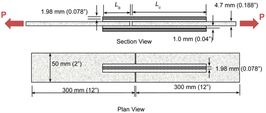
CFRP rod–steel substrate double-lap shear specimen.
Two specimens were tested for each bond length. Table 1 lists the tested specimens, with the corresponding bond length and failure load. The primary mode of failure observed in all the specimens was debonding between the epoxy and steel substrate. Figure 4 illustrates a common form of debonding observed during testing. The failure loads, Pult, observed were averaged and plotted against the bond length, Lb (see Figure 5). Based on these results, the bond strength and development length was estimated as 6.9 kN (1550 lbf) and 50 mm (2 in), respectively. The CFRP rods bonded to the steel substrate achieved approximately 50% of their ultimate tensile strength
Failure loads for double-lap shear specimens with steel substrate.

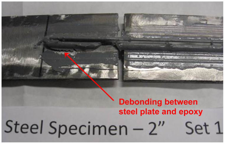
Debonding between steel substrate and epoxy.

Failure load, Pult, versus bond length, Lb, for steel substrate.
Concrete substrate with two CFRP rods
While the steel bond tests provided an estimate of bond strength and development length, in order to evaluate the expected failure load on a concrete substrate, the test was repeated using concrete blocks. The CFRP rods were attached to two opposing sides of concrete blocks along the longitudinal centerline. Figure 6 depicts this layout. The blocks were made from 34.5-MPa (5000-lbf/in2) concrete, and each block had a rebar embedded along its centerline, which let the specimen to be pulled apart in tension (see Figure 6). The concrete blocks were held in place between two steel frames, which permitted bonding of the rods during specimen preparation. This also prevented any lateral or twisting movement between the two blocks during testing. The inside of the steel frame was lubricated to prevent friction between the concrete blocks and steel frame. For the concrete bond tests, only one specimen was made for each of the following bond lengths (Lb): 12.5 (0.5), 50 (2), 75 (3), 100 (4), 125 (5), and 150 mm (6 in). Two specimens were tested for the following bond lengths: 25 (1), 37.5 (1.5), and 175 mm (7 in). The two smaller bond lengths were tested twice to obtain a more accurate estimate of the failure load prior to achieving bond strength. The 175-mm (7-in) specimen was tested again due to a lower-than-expected result obtained from the first test. The control length (Lc) was kept at 200 mm (8 in).
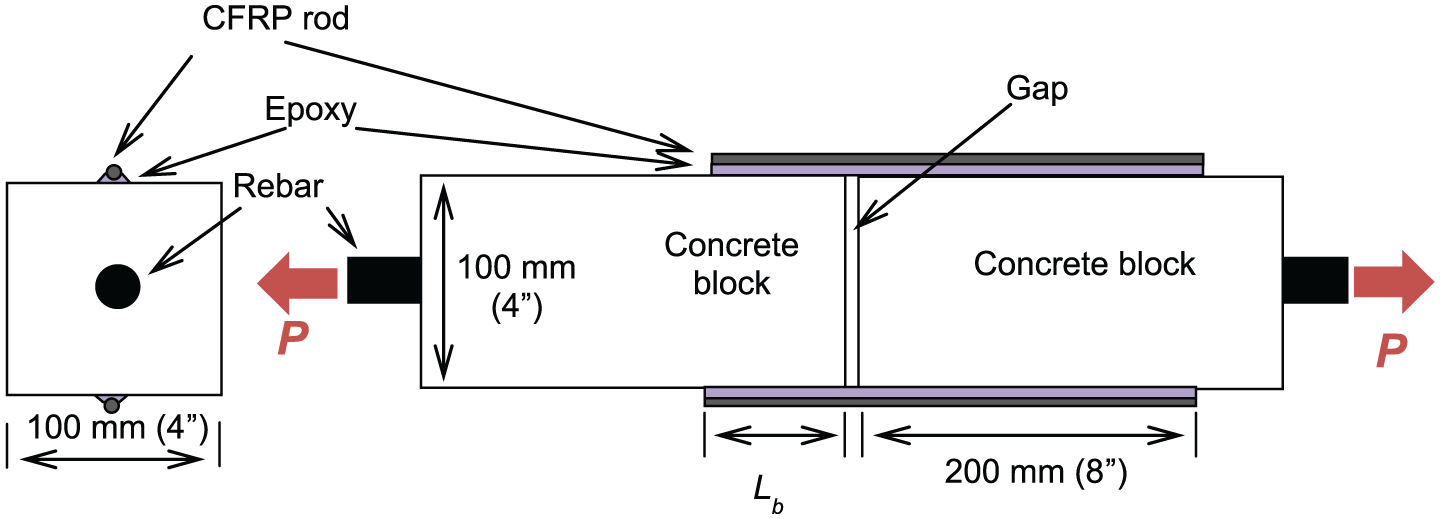
CFRP rod–concrete substrate double-lap shear specimen.
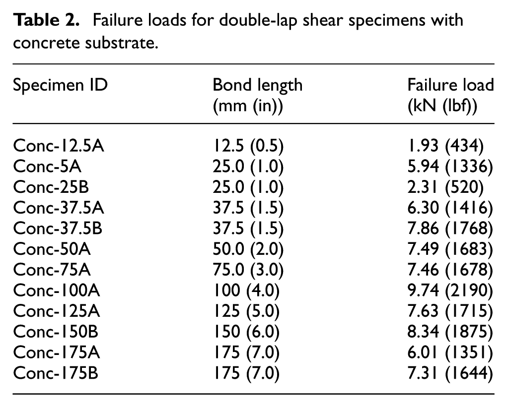
All specimens were loaded to failure. Table 2 lists the bond length and failure load for the double-lap shear specimens with concrete substrate. The predominant failure mode was debonding between the epoxy and the concrete substrate. For some of the longer bond lengths, epoxy cracking occurred prior to failure in debonding. None of the test specimens ruptured the CFRP rods in tension. Figure 7 depicts a typical failure. The ultimate failure load, Pult, is plotted against the tested bond lengths, Lb, in Figure 8. The failure load was averaged for the three bond lengths for which two specimens were tested. The development length for the CFRP rods on concrete substrate was approximately 46 mm (1.8 in), while the bond strength for the specimens was approximately 7.1 kN (1600 lbf). The bond strength and development length for concrete substrate are very similar to the steel substrate results. This would facilitate future bond testing of CFRP rods on steel substrate specimens, which are easier to prepare and test. Similar to the steel substrate specimens, the CFRP rods achieved approximately 50% of their ultimate tensile strength
Failure loads for double-lap shear specimens with concrete substrate.
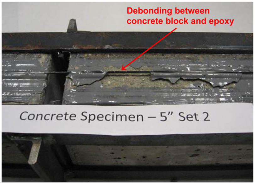
Debonding between concrete substrate and epoxy.
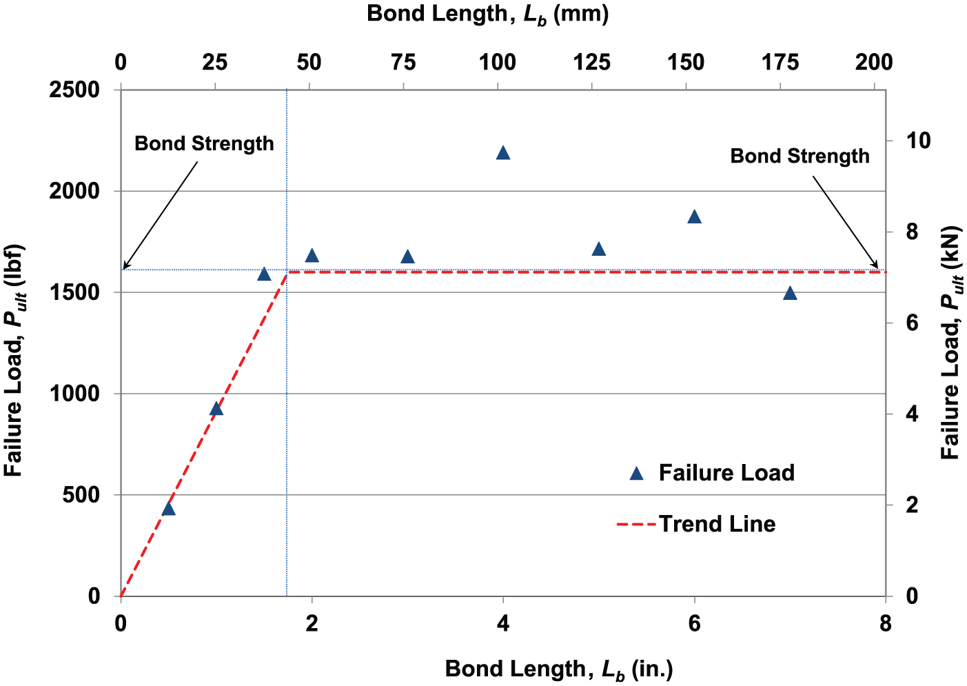
Failure load, Pult, versus bond length, Lb, for concrete substrate.
Steel substrate with CRPs
The individual CFRP rod development length results from the bond tests described in the previous sections established a baseline to design the finger joint for the rod panels. Because fatigue tests were not conducted in this study, the development length (derived in Figures 5 and 8) was increased by 300%, leading to a 150-mm (6-in) finger joint (or overlap splice length). Three double-lap shear specimens (specimen A, B, and C) were made with steel as the substrate, with two panels of CFRP rods having five rods in each panel as the adherend. The bond length on each side, as shown in Figure 9, was 150 mm (6 in). In order to accommodate the larger stresses, thicker mild steel plates were used as the substrate. Similar to the actual panels, the rods were held in place by a self-adhesive glass fiber mesh backing.

CRP–steel bond test specimen.
All specimens initially failed due to the epoxy cracking near the center of the specimen—over the gap between the steel plates. The average failure load for the three specimens at epoxy cracking was 48.7 kN (10.96 klbf), with a minimum failure load being 47.1 kN (10.58 klbf). Due to the sudden drop in stress when cracking began, the testing was stopped. With the exception of cracks in the epoxy and a slight widening of the gap between the steel plates, the specimens remained intact. This was considered a failure, with the CFRP rods achieving almost 72% of ultimate tensile strength

Epoxy cracking and CRP debonding.
Concrete beam tests
Following the completion of the bond strength tests, RC beam tests were carried out to evaluate the performance of the CRPs under flexural loading. Three beams having spans of 2.44 m (8 ft) and 150 mm × 150 mm (6 in × 6 in) cross sections were tested. They were cast using 34.5 MPa (5000 lbf/in2) concrete, and the tensile reinforcement was two #10 steel bars with an area of 71 mm2 (#3 bar with an area of 0.11 in2).
Two different CRP configurations were tested, and the strengthened beams were evaluated against a nonstrengthened control beam. One beam was strengthened using a continuous 2.30-m (7.5-ft) CRP, while the second beam was strengthened using two 1.22-m (4-ft) CRPs with a 150-mm (6-in) finger joint at mid-span. To evaluate its adequacy, the overlap for the finger joint was placed at the center of the beam where the bending moment reaches its maximum. The same 1.98-mm (0.078-in)-diameter CFRP rods were used to fabricate the CRPs. The epoxy resin used in the bond study was also used to attach the CRPs to the concrete beams. The continuous CRP was 125 mm (5 in) wide and consisted of 21 rods. One of the 1.22-m (4-ft) CRPs had 21 rods, while the other had an additional rod (22 rods) to provide symmetry within the finger joint. A layer of epoxy was first placed on the bottom surface of the concrete beam (with the beam lying upside down). Then, the CRP was placed on the epoxy and pressed into it. This let excess epoxy flow out between the rods. The excess epoxy was then spread over the CRP. If necessary, a second layer of epoxy was applied to cover and protect the CRP. Figure 11 illustrates the CRP, with the CFRP rods held in place on a glass fiber mesh, being fused in a finger joint and applied on to the bottom face of the RC beam.
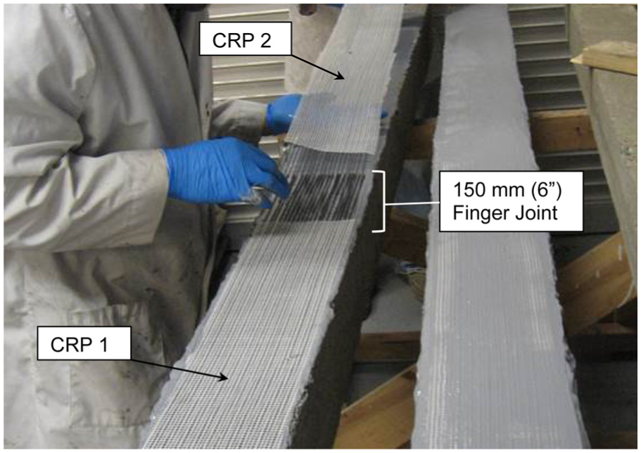
CRPs joined together in a finger joint in test beam.
The beams were tested in flexure using the test setup shown in Figure 12. Displacements were recorded at mid-span, quarter-span, and the reaction frame (to account for any relative displacement). Foil-type strain gages were attached along the bottom face of the beam and at mid-span along the beams’ vertical face to determine the change in the neutral axis. Loads were recorded using a load cell placed above the actuator cylinder head. Figure 13 plots results for the load versus displacement.
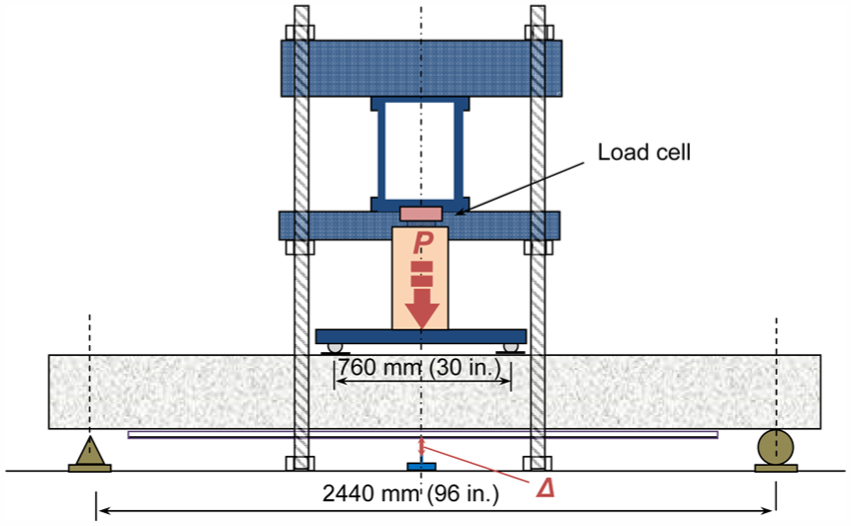
Beam test setup.

Analytical and experimental load versus deflection results.
An analytical study of the unstrengthened and strengthened beams was used to calculate the moment, curvature, load, and deflection points at cracking of concrete, yielding of steel, and ultimate load. The forces in concrete compression were estimated using a modified Hognestad (1951) concrete model. A bilinear relationship, neglecting strain hardening, was used for estimating the forces in the reinforcing steel. In the strengthened beams, the CRPs were applied to the bottom surface of the concrete as an equivalent externally bonded FRP, having the same area as the sum of the CFRP rod area. The thickness of the equivalent FRP was the diameter of the rods. The trilinear load–deflection analytical results are also plotted in Figure 13.
The control beam followed the traditional behavior associated with an under-reinforced concrete section (Figure 13), with an ultimate load of 20.8 kN (4670 lbf) and a deflection of 85 mm (3.33 in) at ultimate. The beam strengthened with one continuous CRP failed at a load of 40.5 kN (9110 lbf) and a deflection of 27 mm (1.06 in). The beam strengthened with two spliced CRPs failed at a load of 35.0 kN (7870 lbf) and a deflection of 36 mm (1.43 in). Compared to the control beam, the increase in ultimate load capacity was 95% and 68% for the continuous and spliced CRP-strengthened beams, respectively. Both CRP-strengthened beams failed in cover delamination (Figure 14). While the spliced CRP-strengthened beam had a lower ultimate load, failure did not occur at the finger joint.
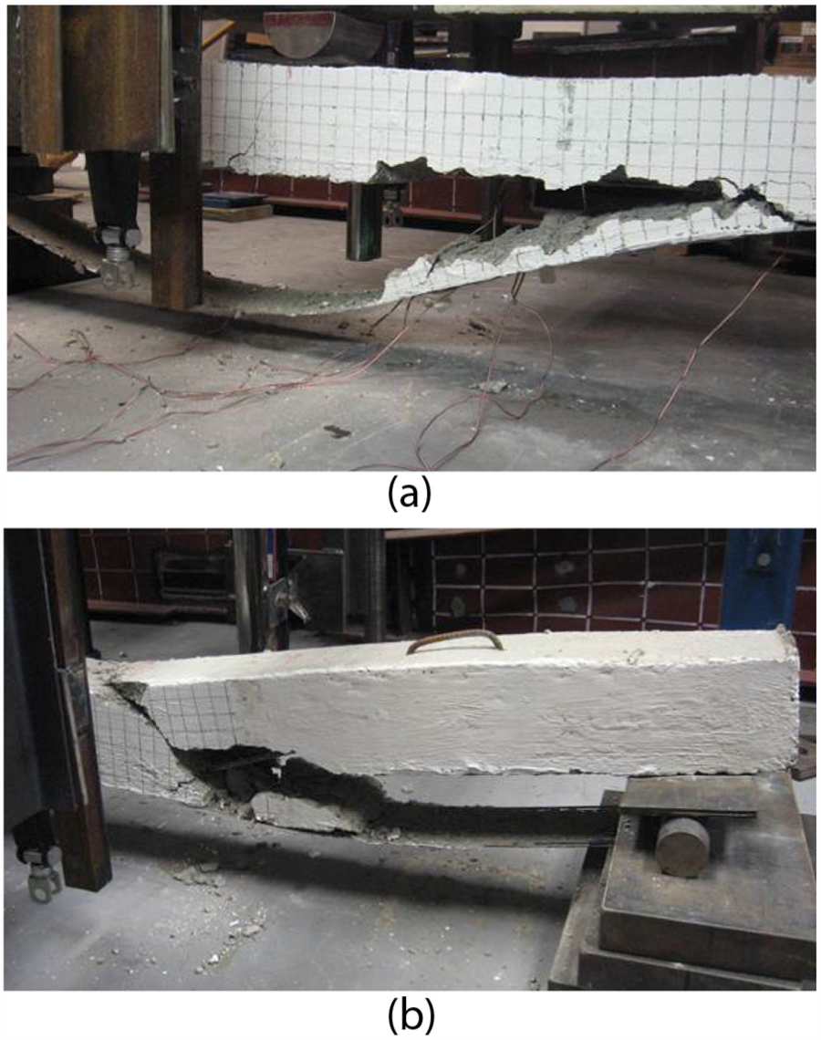
Concrete cover delamination of CRP-strengthened beams: (a) continuous CRP-strengthened beam failure and (b) spliced CRP-strengthened beam failure.
Beam test results validated the capacity of the finger/spliced joint between the CRPs to transfer loads and produce a continuous system that strengthens concrete beams. However, it should be noted that this study dealt with a limited number of test beams. Additional experimental and analytical studies are required to better understand the load transfer behavior within the joint as well as system’s behavior. Fatigue as well as environmental effects and constructability warrant further evaluation. As described previously and employed in the tested concrete beams, the bond length for the finger joint was increased by 300% from 50 (2) to 150 mm (6 in). In addition, due to the absence of detailed test data (which requires additional time and funding), and the need to deploy the CRP system on bridges in Kentucky, it was decided to reduce the design capacity for the CRPs to 30% of the manufacturer-reported ultimate tensile strength
Field applications
The CRPs were primarily developed to retrofit bridges with limited access and to reduce the number of personnel and equipment needs during the retrofit. Nine bridges have been retrofitted in Kentucky with the CRP system from September 2011 through June 2015. Table 3 summarizes the type of bridge, the type of damage, and retrofit carried out for the nine bridges. Of the nine bridges retrofitted, four are discussed in more detail in the following sections. The objective of each bridge retrofit is to increase the capacity of the deteriorated or damaged beam to that of the original beam and to ensure that the stress in CRPs
CRP-strengthened bridges.
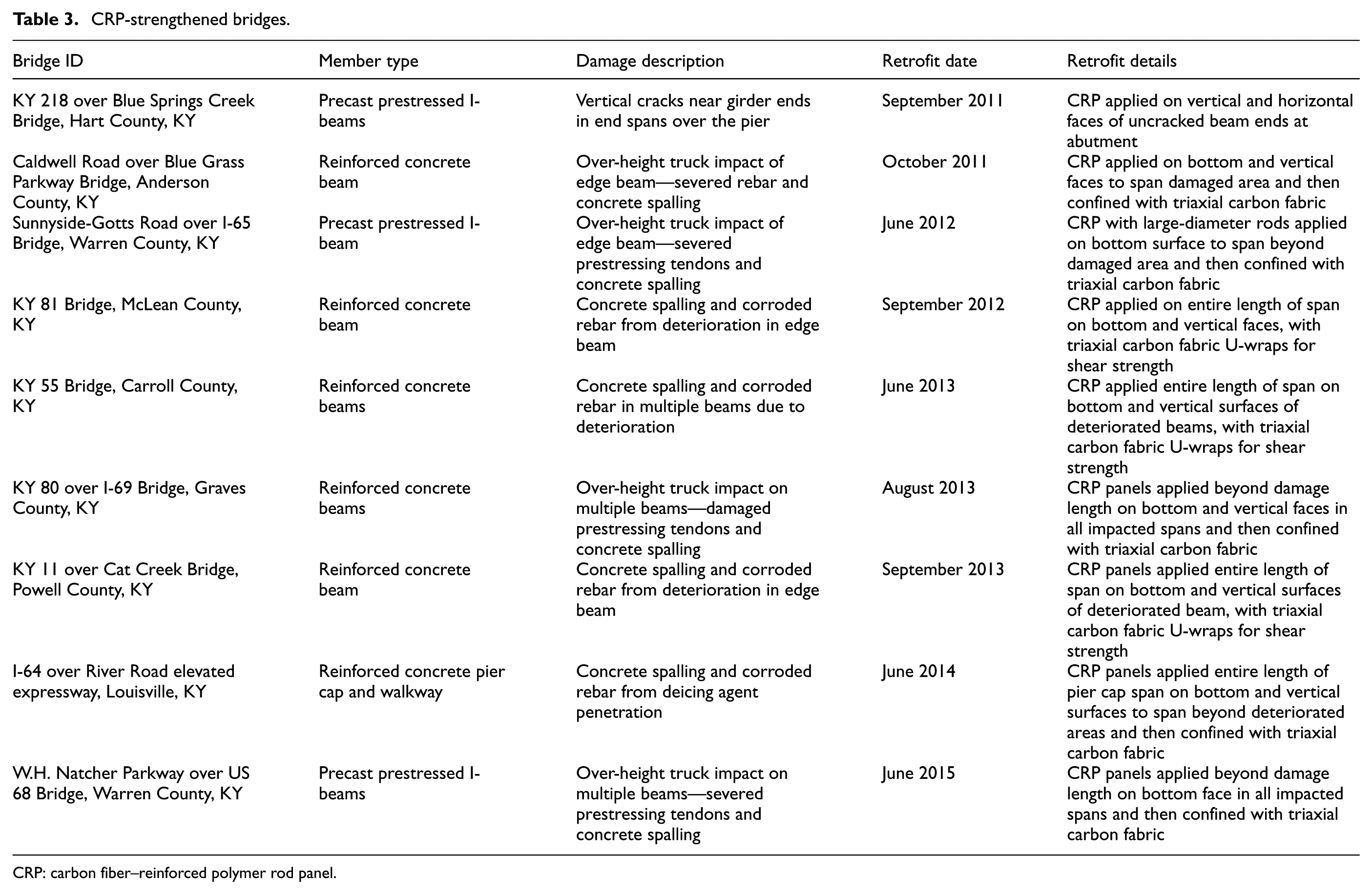
CRP: carbon fiber–reinforced polymer rod panel.
KY 218 Bridge—first field application of CRPs in September 2011
AASHTO type I precast girders on the three-span bridge on KY 218 over Blue Springs Creek in Hart County, Kentucky, developed vertical cracks in the girder webs near the piers in the end spans. The initial retrofit consisted of filling the cracks with epoxy and strengthening the cracked locations with steel fiber–reinforced polymer (SFRP) fabric. To prevent future cracking, the remaining uncracked beams on either side of the piers were strengthened with SFRP fabric.
In order to evaluate the field application of the CRPs, the abutment ends—although uncracked—were strengthened. The CRPs were placed on the vertical sides of the web and bottom flange as well as the bottom face of the girder (see Figure 15). CRP 070, with a tensile load carrying capacity exceeding 310 kN (70,000 lbf) per 300 mm (1 ft) width, was oriented along the longitudinal direction of the girders (normal to the cracks). While the application of the CRP was a precautionary measure with no panel splicing required, it provided valuable methodological insights on applying the epoxy as well as handling and installing panels in the field.
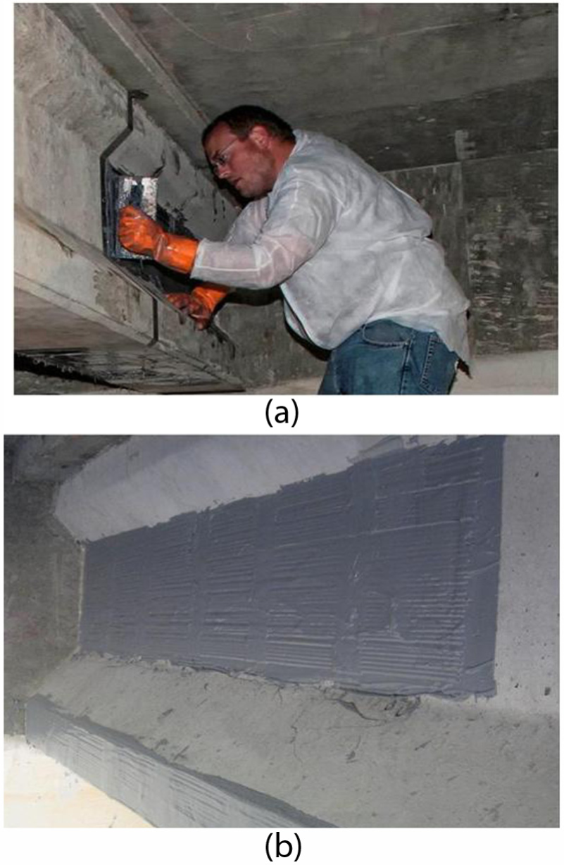
CRP application on KY 218 Bridge: (a) application of epoxy for CRPs and (b) CRP-strengthened girder.
Caldwell Road Bridge (October 2011)
The four-span RC girder bridge on Caldwell Road, which passes over the Blue Grass Parkway in Anderson County, Kentucky, suffered impact damage to one of the edge girders over the eastbound lane of the parkway. As Figure 16(a) reveals, the over-the-height truck impact caused one of the five #36 (area =1006 mm2; #11, area = 1.56 in2) reinforcing bars in the bottom mat to break. Considerable spalling of concrete was visible on the outside surface of the girder. A moment–curvature analysis (Figure 17) was conducted to evaluate the loss in capacity of the beam following the impact damage and calculate the increase in ultimate moment capacity following CRP application. The service moment (Ms) was calculated, accounting for dead loads on the impacted beam prior to CRP application. In the retrofit design, the stresses in the CFRP rods were restricted to 30% of

Retrofit of Caldwell Road Bridge over Blue Grass Parkway: (a) impact damage on RC girder and (b) CRP 080 application.

Moment–curvature analysis for Caldwell Road Bridge.
The retrofit replaced the lost concrete and applied CRPs to replace the loss in strength caused by the damaged rebar. The CRPs used for the retrofit had CFRP rods with a slightly larger diameter—2.2 mm (0.088 in)—than the rods used previously (1.98 mm). They were designated CRP 080 due to a tensile load carrying capacity that exceeded 355 kN (80,000 lbf) per 300 mm (1 ft) width. Carbon fiber fabric was wrapped around the beam’s repaired section to prevent concrete from spalling and falling on the traveling public in the event of future impacts.
The moment–curvature plots in Figure 17 show that the retrofitted beam has a capacity equal to that of the original beam when the stress level in the CRPs is
Sunnyside-Gotts Road Bridge (June 2012)
The Sunnyside-Gotts Road over Interstate 65 (I-65) in Warren County, Kentucky, is a four-span bridge with AASHTO type III precast girders. The outside girder was damaged by an over-height truck impact (Figure 18(a)). The damaged section spanned the right two northbound lanes of the three-lane interstate highway. The over-height truck impact produced significant concrete spalling along with two severed prestressing strands; several wires in two additional strands experienced additional damage. The four strands affected by the impact represented 11% of the prestressing steel.

Retrofit of Sunnyside-Gotts Road Bridge over Interstate 65: (a) impact damage on PC girder and (b) CRP 195 application.
Traffic on I-65 is heavy, and repairs during the day were not permitted. Repairs were carried out at night from 9:00 p.m. to 6:00 a.m. CRP 195, with CFRP rods of 3.96 mm (0.156 in) diameter, having a capacity of 870 kN (195,000 lbf) per 300 mm (1 ft) width of panel, were selected for the strengthening. Two CRP 195 panels, each of which was 225 mm (9 in) wide, were placed side by side on the underside of the bottom flange of the impacted beam. These spanned the width of the bottom flange (Figure 18(b)). The strengthened section of the beam was 7.6 m (25 ft) long, and the CRP application was completed in a single night by two workers working off a truck-mounted work platform. Although larger diameter rods were required due to the magnitude of load carrying capacity lost, the heavier panels did not complicate the application. In case the CRP system could not have been applied in one night, the finger joint between adjacent panels would have provided the means to discontinue strengthening at a specific location. Application could have been finished days or weeks later if the finger joint portion of the last panel to be applied was left exposed and devoid of epoxy. Following the CRP application, the retrofitted area of the beam was covered in triaxial carbon fiber fabric to provide confinement and prevent debris from falling on the interstate below in the event of a future impact.
KY 81 Bridge (September 2012)
A RC bridge on KY 81 in McLean County, Kentucky, had extensive concrete spalling and steel corrosion in reinforcing bars in one of the outside girders. In one rebar, corrosion accounted for over 70% of section loss at a number of locations. All five of the #19 (area =284 mm2; #6 area = 0.44 in2) reinforcing steel bars in the beam had at least 10% section loss throughout the entire length of the beam (8.2 m, or 27 ft). The retrofit design involved a moment–curvature analysis, similar to the one carried out for the Caldwell Road Bridge. CRP 070 was used for this retrofit. Figure 19 depicts the deteriorated RC girder before the retrofit and application of CRP 070 panels. The moment–curvature plots in Figure 20 show that the repaired beam has a capacity equal to that of the original beam when the stress level in the CRPs is

Retrofit of KY 81 Bridge in McLean County: (a) deteriorated RC girder and (b) CRP 070 application.
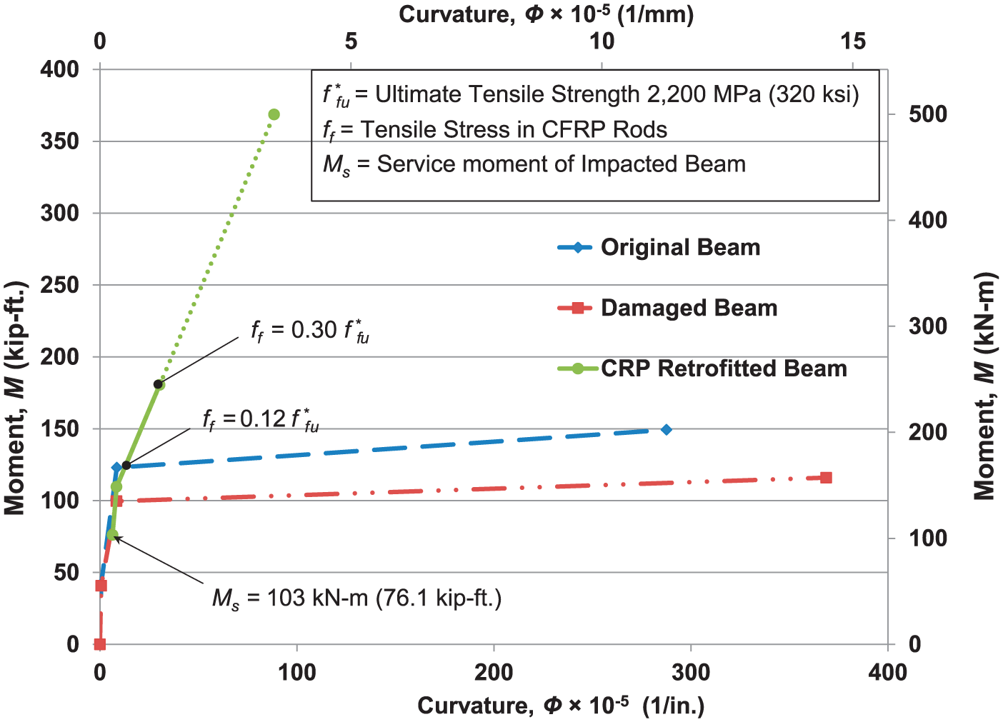
Moment–curvature analysis for KY 81 Bridge.
CFRP laminates could have been used for the retrofit given a dry creek bed below the bridge offered an easy access point. However, applying the CRP system demonstrated the capability of modular construction and provided insight into its application on bridges with limited access.
Conclusion
This study presented the development and deployment of the CRP system. The CRP is connected to adjacent CRPs via a finger joint/splice to produce a continuous system for strengthening concrete structures. The key element in the system is the finger joint and its ability to transfer forcers from one panel to another.
Experimental studies were first conducted to determine the required length for the finger/spliced joint. Testing double-lap shear specimens helped to evaluate the bond strength and development length for individual CFRP rods. Results indicated that the development length was approximately 50 mm (2 in) for the 1.98-mm (0.078-in)-diameter CFRP rod.
Small-scale flexural tests were performed under four-point bending on three RC beams. The beam strengthened with two CRPs, which was made continuous by placing a finger joint at mid-span, failed at a load of 35.0 kN (7870 lbf), whereas the control beam failed at 20.8 kN (4670 lbf). Strengthening a beam with two CRPs yielded a 68% increase in load capacity. The two beams strengthened with CRPs failed due to delamination of the concrete cover. This confirmed that the finger joint was capable of transferring the load from one panel to another. Following the initial laboratory testing phase, the CRP system was deployed on four bridges to evaluate its constructability and to provide insight for refining the system.
It should be noted that this study dealt with a limited number of experimental and analytical tests. Additional studies are required to better understand the behavior of the load transfer within the joint as well as system’s behavior. Fatigue, as well as environmental effects and constructability, also require further evaluation. Currently, different epoxies and rod spacing are the focus of laboratory and analytical modeling. Three-dimensional models of beams, calibrated following experimental studies, are being used to generate numerous scenarios to improve understanding of their behavior and optimize the CRP system. Furthermore, the field applications discussed in this article are undergoing continual inspections to evaluate the long-term durability of the retrofit.
The current method of retrofitting using CFRP laminates is very efficient and cost-effective in flexural strengthening when access to the bridge beams and impact on traffic are minimal. The primary advantage of the CRP retrofit system lies in the ease of its application when the cost of construction access and/or lane closure is costly. A single worker can apply the CRP system which leads to minimal requirements for construction equipment. CRPs are advantageous when repairs and strengthening applications take place over multilane roadways or waterways. Using the CRP retrofit system lets work proceed in sections and, if needed over many days, thus reducing traffic congestion and detours.
Footnotes
Acknowledgements
The authors would like to thank the following students for their assistance with the laboratory testing: Drew Thompson, David Murray, Clay Greenwell, and Akram Jawdhari.
Declaration of Conflicting Interests
The author(s) declared no potential conflicts of interest with respect to the research, authorship, and/or publication of this article.
Funding
The author(s) disclosed receipt of the following financial support for the research, authorship, and/or publication of this article: This research and field deployment reported in this manuscript was funded by grants from the Federal Highway Administration and the Kentucky Transportation Cabinet. A portion of the laboratory testing was funded by the Kentucky Science and Technology Corporation, under grant no. KSTC-144-401-10-039.