
Abstract
Extreme wind events caused damages and losses around the world every year. Windborne debris impact might create opening on building envelop, which would lead to the increase in internal pressure and result in roof being lift up and wall collapse. Some standards including Australia Wind Loading Code (AS/NZS 1170:2:2011, 2011) put forward design criteria to protect structures against windborne debris impacts. Structural insulated panel with Oriented Strand Board skin and expanded polystyrene core has been increasingly used in the building industry. Its capacity was found insufficient to resist the windborne debris impact in cyclonic areas defined in the Australian Wind Loading Code. Therefore, such panels need be strengthened for their applications in construction in cyclonic areas. In this study, impact resistance capacities of seven structural insulated panels strengthened with steel wire mesh and basalt fibre mesh were experimentally and numerically investigated. The impact resistance capacities were identified by comparing the damage mode, residual velocity and unpenetrated length of projectile after impact. Experimental results clearly demonstrated the enhancement of the impact resistance capacities of panels strengthened with steel wire mesh and basalt fibre mesh. Finite element model was developed in LS-DYNA to simulate the dynamic response of the structural insulated panels under windborne debris impact. The accuracy of the numerical model was validated with the testing data.
Keywords
Introduction
A variety of natural disasters happens across the world every year. The insurance company in the United States reported that natural windstorms have caused billions of dollars of economic loss (Tamura, 2009). In Australia, Cyclone Larry (Ginger et al., 2007) in 2006 alone caused about a billion dollar loss and Cyclone Yasi (Boughton, 2011) in 2011 resulted in even higher economic losses. During a windstorm, loose objects (e.g. roof tiles, broken tree trunks and gravels) might be lifted up, propelled by strong wind at relatively high speeds and impact on building envelopes. Upon impacting, they have high probability to damage and penetrate the building envelope such as wall, roof, door, windows, window shutters and screens(Minor et al., 1972). It was reported that most of the damages to the residential building envelope in strong winds was caused by the windborne debris (Sparks et al., 1994). If the debris impact causes an opening on the building envelope, it leads to the increase in internal pressure by letting the wind blowing through, which might result in more severe damage such as roof lifting up and wall collapse. The damaged building might generate more debris into the windstorm and other buildings, thereby experiencing further windborne debris impacts (Tamura, 2009). The post-storm surveys of the above, as well as other extreme wind events such as Hurricane Hugo (Hook et al., 1991) and Hurricane Andrew (Rappaport, 1993) all reported that windborne debris was a major contributor to the building damage and property loss. Therefore, in order to reduce the debris threat to buildings, it is necessary to protect building envelope against windborne debris impact.
Some research work on the windborne debris impact has been undertaken. Braden and Scheer studied the performance of the public and commercial buildings under large projectile impact (Braden, 2004; Scheer, 2005). The experimental tests were conducted on the metal cladding panels subjected to projectile impacts using an air cannon tester (Frye et al., 2012). The impact resistance capacity was determined by the shape of debris, the impact angle and the compressive and shear strengthen of the target material (Backman and Goldsmith, 1978; Børvik et al., 1999; Chen et al., 2006; Corbett et al., 1996; Faggiani and Falzon, 2010; Wilkins, 1978). Structural insulated panels (SIPs) were tested in a previous study subjected to debris impact (Parker, 1986) as such panels are getting more and more popularly used in Canada, Australia, the USA and parts of Europe in residential, industrial and commercial buildings. The SIPs have the advantages of fire resistance, thermal insulation and being easily assembled (Porter, 2001). The SIP usually consists of an expanded polystyrene (EPS) foam core and two skin layers, which are made of various materials such as steel sheet, fibre cement board and Oriented Strand Board (OSB). Very limited studies of SIPs subjected to dynamic loadings such as blast and impact loading have been reported. Recently, Chen and Hao conducted a series of studies of various building envelops subjected to windborne debris impacts (Chen et al., 2014b; Chen et al., 2016b; Chen and Hao, 2014, 2015a, 2015b; Hao et al., 2015) and examined the impact resistance capacities of seven common structural panels used in Australian building industry through impact tests and numerical simulations. It was found that the failure mode of SIPs with brittle skins was primarily localised punching shear failure, while that of panels with ductile skins such as flat and corrugated steel skins were either local punching shear failure or global flexural deformations of the entire panels, depending on the impact velocity and boundary conditions. The test results indicated that the OSB skin SIP could not resist the debris impact at the specified velocity in Australian Wind Loading Code (AS/NZS 1170:2:2011, 2011), that is, the design wind velocity VR equal to 110 m/s for 10,000 years return period or 88 m/s for return period of 500 years, with the corresponding debris impact velocity of 44 and 35.2 m/s, respectively.
OSB skin SIP consists of three layers, including two layers of OSB skins and one EPS core. The properties of the materials are given in Table 2. As OSB panel is eco-friendly representative of current SIP industry and is more and more popularly used in constructions, it is chosen in the study to examine the efficiency of various strengthening measures with stronger skins, cores and interlayers for debris impact resistance. To meet with the design requirement of Australian Wind Loading Code (AS/NZS 1170:2:2011, 2011), the OSB skin SIPs need to be strengthened for their use in specific areas. There are many techniques available to strengthen structural panels to enhance their performance. Basalt fibre cloth and glass fibre laminate were used to strengthen the OSB skin SIP and demonstrated the effectiveness of such strengthening in improving the impact resistance capacities of the strengthened panels (Meng et al., 2016a, 2016b). The strengthening strategy is that letting the front brittle layer damage to absorb energy and back softer layer to deform and prevent penetration. It is noted that glass fibre-reinforced plastic (GFRP) laminate used as face-sheet in the sandwich panels has been increasingly studied due to its light weight of sandwich structure, but it is out of the scope of this study. Reinforced concrete (RC) beams were strengthened with steel wire mesh and found the flexural load-carrying capacity and stiffness were improved as compared to the non-strengthened beam (Nie et al., 2005). The steel wire mesh–strengthened T-type beam was investigated and found both the flexural capacity and the stiffness of the beam increased (Huang et al., 2007). The concrete panel strengthened by steel wire mesh was investigated and reported that the use of steel wire mesh could effectively mitigate the response of the panel (Morton et al., 2007). The steel wire mesh RC slab was found to have higher ultimate load capacity as compared to the non-strengthened slab (Ibrahim, 2011). It was found that using steel wire mesh was effective to enhance the axial strength of the column (Kumar and Patel, 2016). The steel wire mesh–strengthened concrete tube was studied and found that the compressive behaviour of strengthened specimen was enhanced (Gao et al., 2015). Steel wire mesh was also used to strengthen concrete slab. It was found the steel wire mesh reinforcement provided additional spall and crater resistance and effectively reduced the perforation damage under blast loads (Li et al., 2017a; 2017b). Both fibreglass mesh and steel wire mesh were used to strengthen ferrocement beams (Shaheen et al., 2014). It was reported that the beam strengthened with fibreglass meshes had a lower crack loading capacity as compared to that strengthened with steel wire mesh. No study of using steel wire mesh and basalt fibre mesh to strengthen SIPs to increase the impact resistance capacity of the panel can be found in literature yet. As compared to basalt fibre cloth in the previous study (Meng et al., 2016a), steel wire mesh and basalt fibre mesh have the advantages of low cost and lightweight. Therefore, they could replace fibre cloth in strengthening SIPs for certain applications.
In this study, the performances of OSB skin SIPs strengthened by steel wire mesh (∅0.64 mm, 6.5 ×6.5 mm spacing) and three types of basalt fibre mesh (∅1 mm, 10 × 10 mm spacing adhesive coated, 10 × 10 mm spacing uncoated and 5 × 5 mm spacing adhesive coated) under windborne debris impact are experimentally investigated using air cannon impact testing system. The strengthening layer of steel wire mesh and basalt fibre mesh is shown in Figure 1. The material properties of the strengthening mesh layers are given in Table 2. Numerical models are also developed to simulate the responses of OSB skin SIPs strengthened by steel wire and basalt fibre mesh. The accuracy of the models is verified by the experimental results.

Photograph of steel wire mesh roll (L); photograph of basalt fibre mesh (R).
Experimental investigation
A total of seven specimens were manufactured and tested using an air cannon impact system with a wood projectile specified in the Australian code (AS/NZS 1170:2:2011, 2011). The damage modes were observed and the measurements including the projectile impacting velocity and the residual velocity were recorded through two high-speed cameras. The specimens and the schematic diagram of experimental setup are detailed below.
Description of specimens
The specimens of unstrengthened OSB skin panel are commercially available and commonly used in building construction. The panel has a total thickness of 120 mm, consisting of two layers of 10-mm-thick OSB skins and a layer of 100-mm-thick EPS core. The dimension of the specimens tested is 1200 × 800 mm. As will be demonstrated later in this article, the panels under projectile impact suffered primarily localised punching shear failure. Therefore, the height and width as well as the boundary condition of the panel specimen have insignificant influence on its performance in resisting the projectile impact. The unstrengthened OSB skin SIP has been studied in a previous study (Meng et al., 2016a). Some results are briefly presented here as reference to evaluate the effectiveness of the strengthening measures.
In this study, the reference panel is strengthened with one or two mesh layer(s). The strengthening layer can be an interlayer between the OSB skin and EPS core or on the front of the panel. Figure 2 illustrates the three positions of the strengthening layers considered in the study. The specimens A and B are strengthened with a layer of 6.5 × 6.5 mm spacing galvanised steel wire mesh and a layer of 10 × 10 mm spacing adhesive-coated basalt fibre mesh interlayer between the front OSB skin and EPS core, respectively. The coating used for the coated basalt fibre mesh is made of styrene-acrylic latex, which has limited effect on the tensile strength of basalt fibre mesh. The specimen C is strengthened with a layer of 10 × 10 mm spacing adhesive-coated basalt fibre mesh on the front of the panel. The specimen D is strengthened with a 10 × 10 mm spacing uncoated basalt fibre mesh between the front OSB layer and EPS core. The specimen E is strengthened with a 5 × 5 mm spacing adhesive-coated basalt fibre mesh interlayer. The specimen F is strengthened with two layers of galvanised steel wire mesh interlayers between the EPS core and the front and back OSB skins. The specimen G is strengthened with two 10 × 10 mm spacing adhesive-uncoated basalt fibre mesh interlayers. The strengthening mesh layer is bonded to the OSB skin and EPS core using SIP manufacture adhesive. The strength of adhesive provided by the manufacturer is about 6–7 MPa.
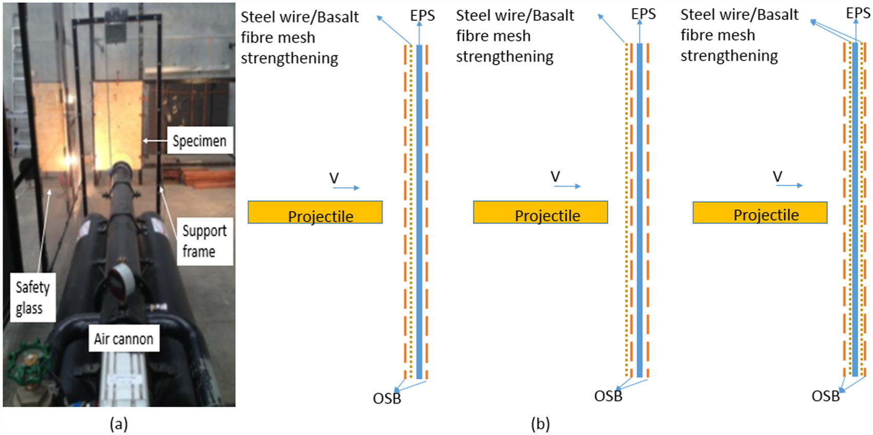
Testing apparatus (air cannon impact system); schematic diagram of steel wire mesh and basalt fibre mesh strengthening position interlayer strengthening (specimen A/B/D/E); front strengthening (specimen C); double interlayer strengthening (specimen F/G).
Experimental setup
The testing system including an air cannon, a support frame, two high-speed cameras and four halogen lights. The experimental setup is shown in Figure 2. The specimen was clamped onto the support frame along the edges of the SIP (i.e. three clamps for each of left and right edges and two clamps for each of top and bottom edges as shown in Figure 3 (E)). The halogen lights were used to provide sufficient light for the high-speed camera recording. A 4-kg timber projectile of 100 × 50 mm cross section, as specified in Australian code (AS/NZS 1170:2:2011, 2011), was launched by air cannon system to impact the targeted panel. The pressure vessel on the air cannon system can be adjusted to obtain the desired impact velocity in the tests. The projectile impact and residual velocities were obtained from the high-speed camera images. It is noted that it is possible to perform some low-velocity impact tests to identify the performance of the panel before conducting large-scale impact tests. However, the testing results from low-velocity impact are not necessarily extrapolatable to predicting the panel resistance to high-velocity impact. This is because the dominant response mode of the panel under different impact velocities might change.

Damage modes of specimen A strengthened with a steel wire mesh interlayer, specimen B strengthened with an adhesive-coated basalt fibre mesh (10 × 10 mm spacing) interlayer, specimen C strengthened with adhesive-coated basalt fibre mesh (10 × 10 mm spacing) at front and specimen D with an uncoated basalt fibre mesh (10 × 10 mm spacing) interlayer, damage mode of specimen E strengthened with an adhesive-coated basalt fibre mesh (5 × 5 mm spacing) interlayer.
Experimental results
In this study, the results were classified as ‘Pass’ and ‘Fail’ as per the Australian Wind Loading Code (AS/NZS 1170:2:2011, 2011). ‘Pass’ means no opening was created after the impact. ‘Fail’ indicates either the debris penetrated the SIP or severe through cracks appeared on the SIP that allows wind blowing through the opening. The residual velocity of the debris, either passing through or rebounding, and the unpenetrated length of the projectile if the projectile stayed in the panel were also measured to compare the impact resistance capacity. In addition, the damage modes of each tested panel were also recorded. Together with the measured quantitative data, they are used to calibrate the numerical model. The detailed testing scheme and results are given in Table 1.
Testing scheme and results.

− indicates rebound velocity after impact.
Damage modes
The non-strengthened SIP in the previous study (Meng et al., 2016a) is used as the reference panel in this study. The critical velocity was determined in the tests when the 4-kg projectile penetrated the panel and stayed on it. With a higher or lower velocity, the debris would penetrate through the panel with a punching shear failure mode or rebound back leaving a dent on the panel, respectively. It was reported that the critical velocity of the non-strengthened SIP with the total thickness of 120 mm was 18 m/s. The global structural response such as panel bending was not observed after impact. The reference panel experienced localised punching shear failure. Therefore, multiple impacts on the panel at different locations were considered as independent events.
The specimen A strengthened with a steel wire mesh interlayer was subjected to two impacts at the velocities of 22.8 and 20 m/s, respectively. Both impacts resulted in punching shear failure as shown in Figure 3. The projectile with the impacting velocity of 22.8 m/s penetrated the panel, but stayed on the panel when the impact velocity is 20 m/s. The impact velocity of 20 m/s is therefore identified as the critical velocity of the strengthened specimen A. Compared to the unstrengthened panel with the critical velocity of 18 m/s, strengthening the panel with a steel wire mesh interlayer only marginally increases its impact resistance capacity.
The specimen B is a SIP strengthened with a 10 × 10 mm spacing adhesive-coated basalt fibre mesh interlayer. A total of two impacts were conducted on this specimen. As shown in Figure 3, the impact with the velocity of 18 m/s had a result of ‘Pass’ and left an indentation on the front OSB skin. The projectile with the velocity of 20 m/s penetrated and stayed on the panel, which led to a result of ‘Fail’. Neither crack at the back nor boundary failure after the impact was observed. The critical velocity is determined as 20 m/s for the specimen B. These results indicate that strengthening the panel with the ∅0.64 mm, 6.5 × 6.5 mm spacing steel wire mesh layer and the ∅1 mm, 10 × 10 mm spacing basalt fibre mesh layer have similar efficiency on the impact resistance capacity of the panel.
The specimen C is a SIP strengthened with a 10 × 10 mm spacing adhesive-coated basalt fibre mesh at the front skin. Two impacts at the velocities of 22 and 20 m/s were tested on this specimen. As shown in Figure 3, both impacts yielded the result of ‘Fail’. The projectile with impact velocity of 22 m/s penetrated through the panel and the projectile with 20 m/s impact velocity penetrated and stayed in the panel. The punching shear failure was observed after the impact. No crack at the back or boundary failure was observed after the two impacts. 20 m/s is again identified as the critical penetration velocity of the specimen C. These results indicate that placing the strengthening mesh layer on the front OSB skin or as an interlayer has the similar effectiveness on improving the impact resistance of the panel. These observations are different from those made in previous study (Meng et al., 2016a), in which it was concluded that placing basalt fibre cloth at different locations affects the impact resistance capacity of the SIP. These results indicate that the improvement in the impact resistance capacity using steel and basalt fibre mesh is insignificant as compared to strengthening the panel with basalt fibre cloth. This conclusion is expected because fibre cloth has higher strength than the steel wire and fibre meshes.
The specimen D, similar to the specimen B, was strengthened with a 10 × 10 mm spacing basalt fibre mesh interlayer. The difference is that the specimen D used uncoated basalt fibre mesh, while the specimen B used coated basalt fibre mesh. The specimen D was subjected to two impacts at the velocities of 20 and 18 m/s, respectively. The panel experienced a typical punching shear failure and an indentation as shown in Figure 3. The 4-kg projectile with velocity of 18 m/s impacted on the panel and rebounded with a velocity of 4.8 m/s. When the impact velocity was 20 m/s, the projectile penetrated and stayed on the panel. These results indicate that coating basalt fibre mesh has no prominent effect on the impact resistance capacity of the panel. This is because the fibre mesh was coated with a very thin layer of epoxy resin. The strength of the epoxy layer and the energy dissipated by the thin layer coating are trivial as compared to the high impact load and the total impact energy. The thin adhesive coating on basalt fibre mesh is not simulated in the numerical model of specimen B.
The specimen E was strengthened with an adhesive-coated basalt fibre mesh interlayer (∅1 mm, 5 × 5 mm spacing). It was subjected to two projectile impacts at the velocities of 16 and 20 m/s, respectively. As shown in Figure 3, the first projectile impact at 16 m/s left an indentation on the panel and the rebound velocity of the projectile was 2 m/s. The second projectile impact at 20 m/s penetrated the panel and stayed on it. No crack was observed at the back of the panel after two impacts. The critical velocity for the specimen E is therefore determined as 20 m/s. These results indicate that reducing the mesh spacing from 10 to 5 mm has insignificant effects on the impact resistance capacity of the panel. As will be discussed later, the panel strengthened with denser fibre mesh has slightly higher capacity than that with coarse mesh by comparing the projectile penetrated length, but the improvement in resisting the 4-kg projectile impact is negligible because of the large impact energy.
The specimen F was strengthened with two steel wire mesh interlayers. It was subjected to two projectile impacts at the velocity of 23.0 and 20.0 m/s, respectively. Both impacts caused localised punching shear failure on the panel as shown in Figure 4. The projectile penetrated through the panel with a residual velocity of 6.6 m/s in the first impact. In the second impact, the projectile penetrated and stayed on the panel after the strike. The critical velocity is determined as 20 m/s for the specimen F. These results indicate that double-layer strengthening has similar effectiveness as single layer strengthening in enhancing the impact resistance capacity of the SIP. This again could be attributed to the relatively low strength of the steel wire mesh as compared to the high projectile impact energy. As will be discussed later, using two layers of steel wire mesh indeed reduced the projectile penetration length, but it is not sufficient to prevent the projectile from piercing through the panel.
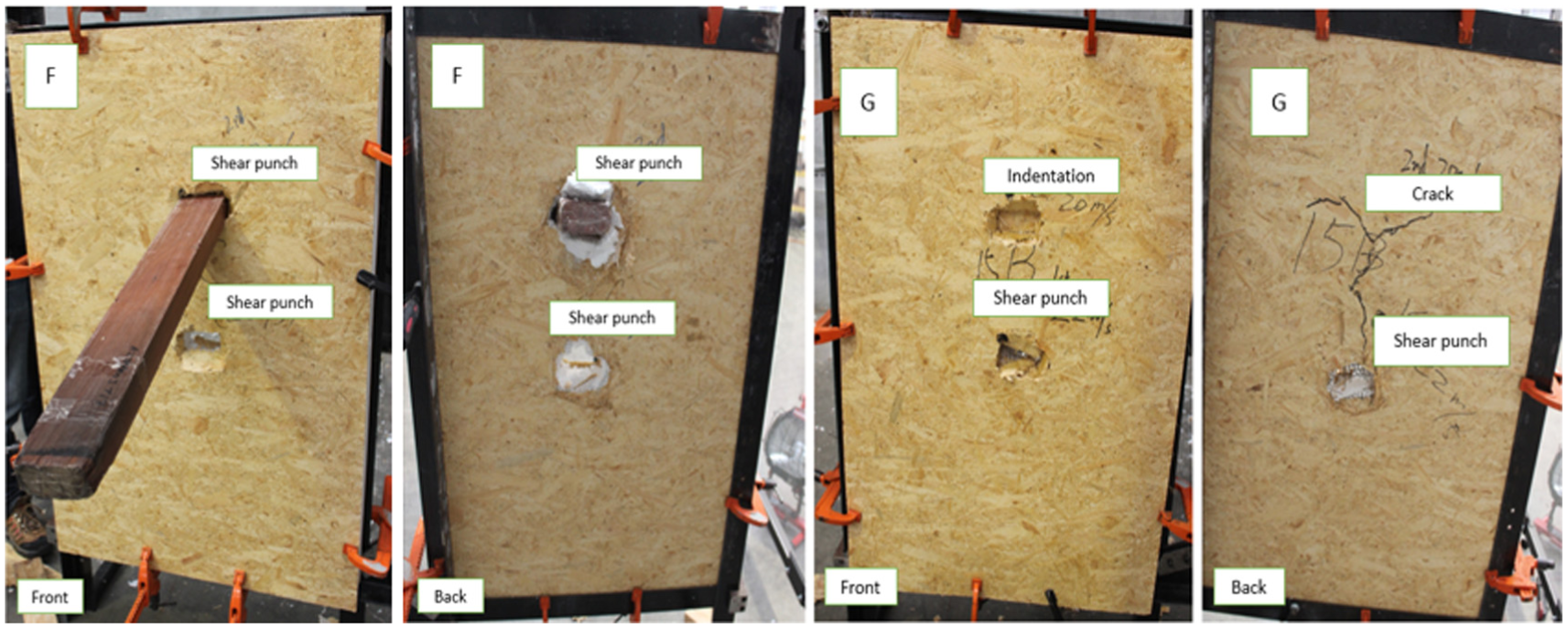
Damage mode of specimen F strengthened with double steel wire mesh interlayers against first 23 m/s impact and second 20 m/s impact (L); damage mode of specimen G strengthened with double uncoated basalt fibre mesh (10 × 10 mm spacing) interlayers first 23.0 m/s impact and second 20.2 m/s impact (R).
The specimen G was strengthened with two layers of uncoated basalt fibre mesh (∅1 mm, 10 × 10 mm spacing). The specimen was subjected to two impacts. The first projectile impact at the velocity of 23.0 m/s penetrated and stayed on the panel after impact. The second projectile impact at the velocity of 20.2 m/s left an indentation on the front skin of the panel. A crack on the back OSB skin was also observed as shown in Figure 4. However, the testing result was specified as ‘Pass’ since the crack was only observed at the back skin; therefore, it is not through crack. The front OSB skin and EPS core can prevent wind flowing through. The critical velocity for the specimen G is therefore determined as 23.0 m/s. These results indicate the double basalt fibre mesh interlayer–strengthened SIP could better resist the impact load than the double steel wire mesh–strengthened SIP. This is because the basalt fibre mesh has higher tensile strength than the steel wire mesh used in this study.
Comparisons of different strengthened OSB skin SIPs
As given in Meng et al. (2016a), regarding the result of projectile impact on the reference panel, the critical velocity for the non-strengthened OSB skin SIP is 18 m/s. All the seven strengthened specimens tested in this study were demonstrated to have higher impact resistance capacity of different levels after adding strengthening layer into the SIP. Due to the brittle attribute of the OSB skin and EPS foam material, the panel experienced localised punching shear failure and indentation damage. Only the specimen G survived the projectile impact at the velocity of 20 m/s. Therefore, the enhancement on the impact resistance capacity of the panel by the strengthening techniques presented in this study is only marginal, indicating steel wire mesh and basalt fibre mesh are not strong enough to strength OSB skin SIP to resist projectile impact. As presented above, in impact tests, the projectile penetrated and stayed on six specimens (A, B, C, D, E and F) at the impact velocity of 20 m/s. Although the panels were considered failed because of creation of opening, the penetration length of the projectile is examined to analyse the impact resistance in more detail. Six specimens (A, B, C, D, E and F) showed different unpenetrated lengths of projectile, which were measured after testing to compare the impact resistant performance. As shown in Figure 5 and Table 1, the specimens A, B, C, D, E and F left 200, 470, 540, 670, 750 and 785 cm of projectile unpenetrated at the critical impact velocity of 20 m/s, respectively. Although these six panels are all considered having the same critical impact velocity of 20 m/s, the above results do indicate some different impact resistance capacities of the strengthening measures in terms of the strengthening material strength, wire mesh density, location and number of wire mesh layers. These are discussed below in more detail.
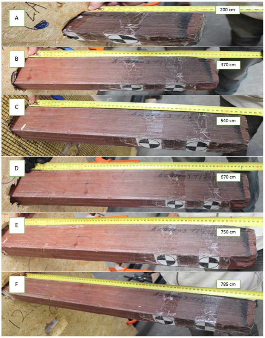
Unpenetrated length of projectile (A/B/C/D/E/F) after impact at the launching velocity of 20 m/s.
The effect of strengthening materials on the unpenetrated length of projectile by comparing specimens A and B; specimens B and D; specimens B and E; and specimens F and G
The projectile’s kinetic energy was mainly absorbed by the penetration of the skins and EPS core with shear failure and the friction between the EPS core and the projectile. By comparing the unpenetrated projectile length of the specimen A strengthened with the 10 × 10 mm spacing steel wire mesh and the specimen B strengthened with 10 × 10 mm spacing adhesive-coated basalt fibre mesh, it can be concluded that specimen B has higher impact resistance capacity than specimen A because the respective unpenetrated projectile length of specimens B and A are 470 and 200 cm, respectively. The difference in the impact resistance capacities of the two specimens can be attributed to the different wire mesh strength and a thin layer of epoxy coating in specimen B. The basalt fibre mesh has higher tensile strength than the steel wire mesh, the thin layer of epoxy coating, as is discussed below, actually has adverse effects on impact resistance of the SIP. However, the higher basalt fibre strength than the steel wire strength still makes specimen B having higher impact resistance capacity than specimen A.
Both specimens B and D were strengthened with the basalt fibre mesh of the same dimension at the same location. The difference is that specimen B was strengthened with adhesive-coated basalt fibre mesh and the specimen D was strengthened with uncoated basalt fibre mesh. It was observed that the specimens B and D left 470 and 670 cm unpenetrated length of projectile, respectively, indicating applying a coating layer has adverse effects on the impact resistance capacity of the SIP. The reason might be that the uncoated fibre strips separates from the OSB skin upon impact and experiences more deformation and hence dissipates more energy than the adhesive-coated fibre strip because coating prevents free deformation of the fibre strip. The results indicate attaching the mesh with epoxy coating makes it more vulnerable to brittle punching shear damage.
The influences of mesh spacing are discussed by comparing the performance of specimen B with 10 × 10 mm spacing adhesive-coated basalt fibre mesh and the specimen E with 5 × 5 mm spacing adhesive-coated basalt fibre mesh. The unpenetrated length of the projectile into specimens B and E is 470 and 750 cm, respectively, indicating reducing the mesh spacing increases the performance of the strengthened panel, as expected. Increasing the density of the basalt fibre mesh can enhance the energy dissipation ability of the strengthened panel. The specimen E (5 × 5 mm spacing adhesive-coated basalt fibre mesh interlayer–strengthened SIP) is considered as the most effective single layer–strengthened SIP against projectile impact, among the single layer–strengthened panels considered in this study.
The specimens F and G were strengthened with double layers of steel wire mesh and uncoated basalt fibre mesh (10 × 10 mm spacing), respectively. As expected, the SIP strengthened with double layers outperformed all panels strengthened with single layer. The projectile penetrated the specimen F with the longest unpenetrated length of 785 cm at the velocity of 20 m/s. The specimen G strengthened with double layers of uncoated basalt fibre mesh (10 × 10 mm spacing) had a higher critical velocity of 23 m/s than the specimen F due to the higher tensile strength of basalt fibre material. The specimen G with double basalt fibre mesh interlayer strengthening has the highest impact resistance capacity among the seven strengthened panels considered in this study.
The effect of strengthening location on the unpenetrated length of projectile by comparing specimens B and C
The specimens B and C were strengthened with the same layer (adhesive-coated basalt fibre mesh) but at different locations. The interlayer-strengthened specimen B left 470 cm unpenetrated length of projectile and the specimen C strengthened on the front of the panel left 540 cm unpenetrated length of projectile, respectively, which indicates that the front strengthening is more effective than placing the strengthening layer as an interlayer. For the interlayer-strengthened specimen B, the mesh layer is backed with soft EPS foam. EPS only provides minimum support to the strengthening mesh, while OSB, although also weak and brittle, could provide more support to the strengthening mesh. The improvement of impact resistant capacity of the panel is limited owing to the mesh layer is easier to be stretched and penetrated under projectile impact. The mesh layer attached on the easily deformed EPS material is prone to fail as compared to that attached on the rigid (OSB) surface. Therefore, the front strengthening method can provide slightly better impact resistance performance due to its enhancement of the penetration resistant capacity of the front OSB skin.
Numerical simulation
Numerical model
The numerical model shown in Figure 6 is developed using commercial software ANSYS. The software LS-PREPOST is used to pre-process and post-process the simulation. The numerical model of the non-strengthened OSB skin SIP was verified in the previous study (Meng et al., 2016a). In this study, the specimens have been strengthened using steel wire mesh and basalt fibre mesh. Therefore, the specimen A strengthened by steel mesh and the specimen B strengthened by coated basalt fibre mesh as representative specimens are presented herein for comparison between the numerical and experimental results. Two finite element models are developed by including the 6.5 × 6.5 mm spacing steel wire mesh (∅0.64 mm) interlayer-strengthened SIP A and the 10 × 10 mm spacing adhesive-coated basalt fibre mesh (∅1 mm) interlayer-strengthened SIP B. The accuracy of the numerical models of the strengthened panels is verified by comparing with the experimental results. The residual velocity of the projectile after impact is used to calibrate the finite element model. In the numerical model, the basalt fibre mesh and steel wire mesh are modelled using beam element. OSB skin and EPS core are modelled with solid element. Based on the mesh convergence test in the previous study (Chen and Hao, 2014), the impact area is modelled with dense (5 × 5 ×5 mm) solid element, and the rest of the panel is modelled with 25 × 25 × 5 mm and 25 × 5 × 5 mm solid element. The steel wire mesh and the basalt fibre mesh in panel are modelled with 6.5 and 5.0 mm beam elements according to the physical sizes of mesh units, respectively. Owing to the symmetrical behaviour of the panel, only a quarter of the panel is modelled to simulate the dynamic response of the panel subjected to debris impacts.
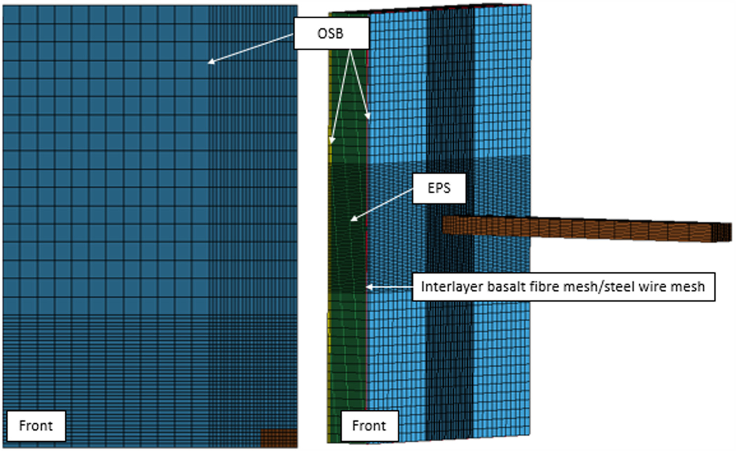
Numerical model (L) quarter model (front view); (R) reflected full model (angled view).
Element types and boundary conditions
The OSB skin and EPS foam are modelled using constant stress single integration node solid elements. The steel wire mesh and the basalt fibre mesh are modelled using Hughes-Liu with cross section integration beam element. The timber debris is modelled using eight-node solid elements. In the tests, all specimens were clamped onto the support frame using G-clamps along the boundary of the panel as described above. The panel boundary is assumed to be fully fixed. The keyword of *BOUNDARY SPC SET is used in the numerical model to simulate the fully fixed boundary condition. It should be noted that this simplification in modelling the boundary conditions does not significantly affect the simulation results because, as observed in the tests, all the panels experienced only local responses and damage.
Material models
The numerical model was built based on the calibrated model in the previous study (Meng et al., 2016a). The material models *MAT 24, *MAT 163, *MAT 143 and *MAT 20 in LS-DYNA are used to model the mesh layer, EPS foam, OSB skin and timber debris, respectively.
As reported in Cruzado et al. (2013), steel wire mesh exhibits elastic plastic behaviour, which can be simulated using *MAT 24 (*MAT PIECEWISE LINEAR PLASTICITY) in LS-DYNA. The elastic-plastic material model *MAT 24 has been widely used to simulate the reinforcement in the concrete structure (Chen et al., 2014a). Basalt fibre cloth was modelled by shell elements using *MAT 54 (i.e. *MAT ENHANCED COMPOSITE DAMAGE) in the previous study (Meng et al., 2016a). However, the *MAT 54 is not applicable to beam element in LS-DYNA. In this study, the basalt fibre mesh is modelled with *MAT 24 since the basalt fibre exhibits approximately linear elastic behaviour before its failure. The failure criterion for basalt fibre mesh is defined by the tensile strength (i.e. 4800 MPa) and failure strain (i.e. 0.01) and the failure criterion of steel wire mesh is defined by failure strain (i.e. 0.1). The material properties of the steel wire mesh and basalt fibre mesh used in the numerical models are listed in Table 2.
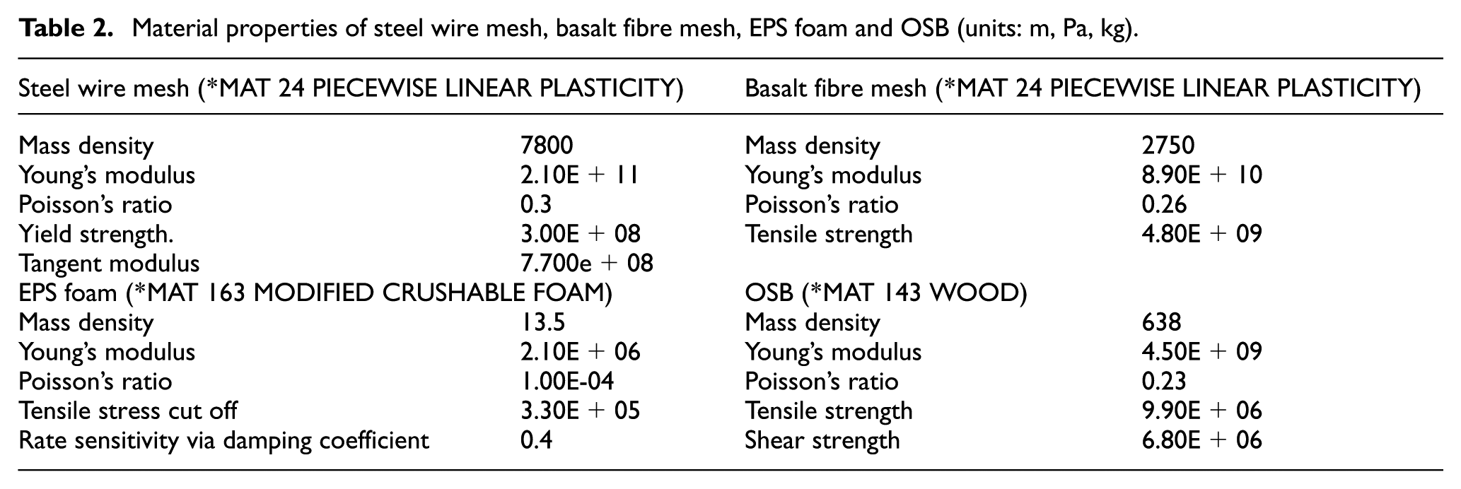
Material properties of steel wire mesh, basalt fibre mesh, EPS foam and OSB (units: m, Pa, kg).
A few material models could be used to simulate the foam material including *MAT 57 LOW DENSITY FOAM, *MAT 63 CRUSHABLE FOAM and *MAT 83 FU CHANG recommend by Croop et al. (2009). Chen et al. (Chen and Hao, 2014) studied the EPS material properties in compression and tension through static and dynamic tests. It was reported that EPS foam was a strain rate sensitive material. The material model of *MAT 163 considering strain rate effect was used for the calibrated EPS material model in the previous studies (Chen et al., 2015; Meng et al., 2016a). *MAT ADD EROSION and hourglass function are applied onto the EPS solid elements to eliminate the possible negative volume. Based on the calibrated OSB material model in the previous studies (Meng et al., 2016a), *MAT 143 WOOD is used to simulate the OSB material in this study. The OSB and EPS material parameters are also given in Table 2. The material model named *MAT 20 RIGID is used to simulate timber projectile as no damage or mass loss of the timber projectile was observed in the tests. The density and Young’s modulus of the timber are defined as 888 kg/m3 and 220 GPa, respectively.
Contact algorithm
Four types of contact algorithm are used to simulate the contact in the numerical models of steel wire mesh–strengthened SIP and basalt fibre mesh–strengthened SIP. *ERODING SINGLE SURFACE is used to define the contact between the projectile and the strengthened panel. *CONTACT ERODING SURFACE TO SURFACE is applied between each contact surface, such as the contact between the EPS foam core and OSB panel. *NODES TO SURFACE is used to model the contact for impact involving the layer of steel wire mesh and the layer of basalt fibre mesh. In the previous study (Meng et al., 2016a), debonding was found between the strengthening layer and the skin layer after projectile impact. Slight debonding was also observed between the wire mesh and the OSB layer in the test. *TIEBREAK NODES TO SURFACE is deployed in the model to simulate the bonding between the steel wire/ basalt fibre mesh and the OSB layer, as well as between the steel wire/basalt fibre mesh and the EPS foam core. The tensile strength of 6.3 MPa and shear strength of 5.7 MPa are used to define the failure of this contact.
Comparisons between test results and numerical results
The testing results of two specimens (i.e. specimen A/B) subjected to four hits in total are used to verify the accuracy of the finite element models. The specimen A is strengthened with steel wire mesh (∅0.64 mm, 6.5 × 6.5 mm spacing) as interlayer and the specimen B is strengthened with coated basalt fibre mesh (10 × 10 mm spacing, ∅1 mm) as interlayer. It should be noted that both panels experienced localised punching shear failure under projectile impacts. The indentation did not affect the subsequent test because a different location was impacted. In the numerical model, each impact is modelled as individual event to strike the specimen. The numerical results are compared with the testing results in terms of damage mode and the residual velocity of the projectile after impact, which are given in Table 3.
Comparisons between testing results and numerical results.
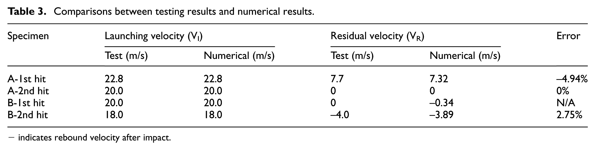
− indicates rebound velocity after impact.
Specimen A
The specimen A was subjected to the first projectile impact at the velocity of 22.8 m/s. As shown in Figure 7, the specimen A experienced typical punching shear failure and the projectile penetrated through the panel. The damage mode can be well captured by the numerical simulation, that is, shear failure of the steel wire mesh at the impact location, and new debris generated after the impact. The predicted residual velocity for the first impact is 7.32 m/s, which is 4.94% lower than the experimental result. The second impact on the specimen A was carried out with a lower velocity of 20 m/s. The projectile penetrated and stayed on the panel with localised punching shear failure. The numerical results well agree with the testing results of the specimen A.
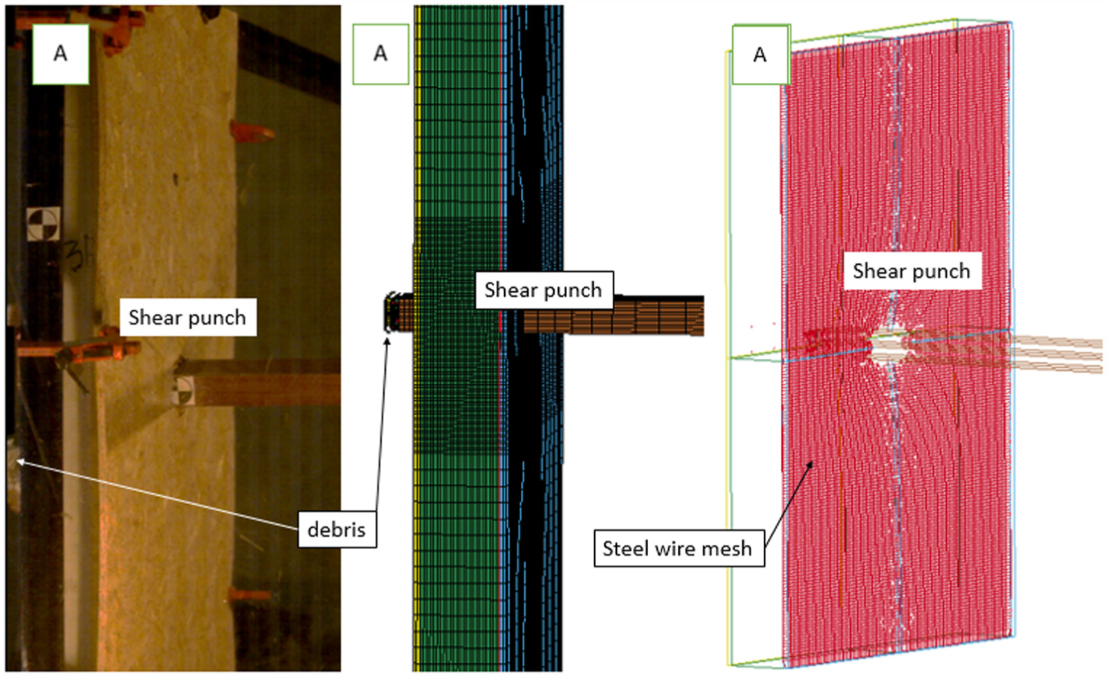
Comparisons of damage mode of specimen A (first impact at 22.8 m/s); (L) test; (M) numerical; (R) numerical (the layer of steel wire mesh).
Specimen B
The specimen B was also subjected to two projectile impacts at the velocities of 20 and 18 m/s, respectively. As shown in Figure 8, a clear localised punching shear failure was observed in experimental test and numerical simulation when the specimen was subjected to 20 m/s projectile impact. The projectile at the first hit penetrated and stayed on the panel in the test while the projectile rebounded with a velocity of 0.34 m/s in the numerical simulation, indicating the numerical simulation slightly over predict impact resistance capacity of the panel. The second projectile impact at the launching velocity of 18 m/s rebounded in both test and numerical simulation. As given in Table 1, the rebound velocity from the test is 4 m/s and the numerical result is 3.89 m/s, with an error of 2.75%. These results indicate that the numerical model can give good predictions of the panel responses to the projectile impact.
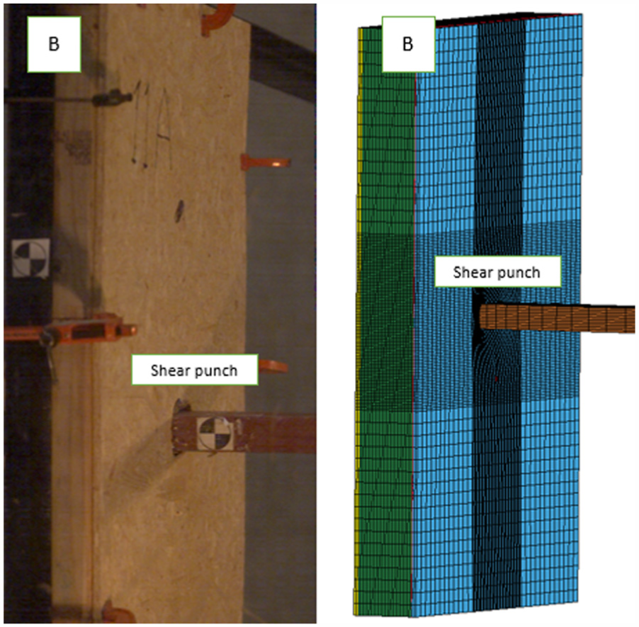
Comparisons of damage mode of specimen B (first impact at 20 m/s); (L) test; (R) numerical.
The above comparisons demonstrate that the developed numerical model can reliably simulate the panel responses subjected to projectile impacts. These numerical models can be used to perform parametric simulations to study the effectiveness of strengthening measures on the impact resistance capacities of OSB SIPs.
Conclusion
In this study, experimental investigations have been conducted to study the effectiveness of using the steel wire mesh and basalt fibre mesh to strengthen OSB skin SIP to resist windborne debris impact. A total of seven strengthened SIP specimens were tested. It was found that the damage modes included indentation and punching shear failure. The application of steel wire mesh in this study was found less effective than basalt fibre mesh in enhancing the impact resistance capacity of the SIP. Coating the basalt fibre mesh with a thin layer of epoxy was found having adverse effect on the impact resistance of the panel. Placing the wire mesh layer on the front OSB surface was found more effective than placing the strengthening layer between the OSB skin and EPS core. While the wire mesh has advantages of light weight and cheap, using wire mesh to strengthen the SIP only marginally increases the impact resistance of the panel. Increasing the mesh strength and density has obvious effect in enhancing the performance, but the cost also increases. Therefore, a balance needs to be sought in practice based on detailed analysis. Two numerical models, that is, steel wire mesh interlayer–strengthened SIP and adhesive-coated basalt fibre mesh–strengthened SIP subjected to debris impact were developed. The accuracy of the numerical models has been verified with test data. The validated model can be utilised to analyse the impact resistant performance of the panel strengthened with basalt fibre mesh and steel wire mesh of different strength and different dimension in design practice to find the optimal strengthening solutions.
Footnotes
Acknowledgements
The authors acknowledge the financial support from Australian Commonwealth Scientific and Industrial Research Organization (CSIRO) through the project ‘Climate Adaptation Engineering for Extreme Events Cluster (CAEx)’. The first author acknowledges the financial support from International postgraduate research scholarship (IPRS) and Australian Postgraduate Award (APA) at Curtin University.
Declaration of Conflicting Interests
The author(s) declared no potential conflicts of interest with respect to the research, authorship and/or publication of this article.
Funding
The author(s) received no financial support for the research, authorship, and/or publication of this article.