
Abstract
The increasing interest in timber as a sustainable construction material has led to the development of a new type of structures referred to as ‘hybrid fibre-reinforced polymer–timber thin-walled structures’. In these structures, thin layers of fibre-reinforced polymer are combined with timber veneers to create high-performance, lightweight and easy-to-construct structural members. This new type of structural members harnesses the orthotropic properties of both timber and fibre-reinforced polymer by appropriately orientating material fibre directions for optimal composite properties as well as efficient thin-walled cross-sectional shapes. Hybrid fibre-reinforced polymer–timber thin-walled members can be used in many applications such as load-bearing walls, roofs, floor panels and bridge decks. This article describes several novel hybrid fibre-reinforced polymer–timber structural member forms and presents results from a preliminary experimental investigation into the compressive behaviour of hybrid fibre-reinforced polymer–timber wall panels. A comparison of behaviour between a hybrid fibre-reinforced polymer–timber wall panel and a pure timber wall panel is presented to show that the hybrid fibre-reinforced polymer–timber system significantly outperforms the pure timber system in terms of both load resistance and axial strain at failure.
Introduction
Fibre-reinforced polymer (FRP) composites have found increasing applications in infrastructure in recent years (Hollaway and Teng, 2008; Keller, 2001). This has mainly been due to the many advantages FRP possesses over traditional construction materials, including high strength-to-weight ratios, excellent corrosion resistance and a reduced construction effort. Over the past two decades, the main focus of the use of FRP in infrastructure has been on strengthening/retrofitting existing structures with FRP. In recent years, more attention has been paid to the use of FRP in new construction (e.g. Fernando et al. 2016; Teng et al., 2007; Zhao et al., 2016). Structural use of FRP in new construction can be divided into two categories: all-composite and hybrid structural members.
All-composite structures are predominantly used as lightweight structures (e.g. Keller, 2001), where pultruded, filament-wound and hand-laminated FRP profiles similar to thin-walled steel profiles are typically used (e.g. I or hollow sections). Due to factors such as the relatively low compressive resistance of FRP, the material cost of an all-FRP structure is generally high. In the civil engineering context, the advantages of FRP are often better exploited in hybrid structural members that combine the complementary properties of the constituent materials for optimum member performance. FRP–concrete hybrid systems have thus been a major focus of existing research as the high tensile strength of FRP is a natural complement to the high compressive strength of concrete. Examples of efficient FRP–concrete systems include double-skin tubular columns (Teng et al., 2007) and beams (Zhao et al., 2016) employing filament-wound FRP confining tubes with fibres oriented close to the hoop direction.
The structural use of FRP with timber has predominantly been concerned with the strengthening/retrofit of existing timber structures (e.g. Kropf and Meierhofer, 2000; Theakston, 1965). A small number of studies have examined FRP-reinforced timber elements for new construction (Fernando et al., 2016; Moulin et al., 1990; Raftery and Harte, 2011). It has been demonstrated that the use of a small amount of FRP can significantly enhance the performance of low-quality wood (Fernando et al., 2016). Recent advances in engineered timber products have led to the development of veneer-based composite (VBC) sections (Gilbert et al., 2014a, 2014b). VBC sections include thin-walled sections made of cross-laminated veneers (Gilbert et al., 2014b) and compact sections made of veneers with the grain orientation being in the axial direction of the member (Gilbert et al., 2014a). To maximize the buckling strength of VBC thin-walled members, efficient cross-sectional shapes similar to those of thin-walled cold-formed steel sections were used. VBC thin-walled sections possess two obvious advantages over their compact counterparts: (a) the former have a higher load-carrying capacity than the latter for a given amount of material and (b) the former do not suffer from weak transverse (to the grain direction) properties associated with the latter where the veneer grain directions are the same. VBC thin-walled sections are, however, difficult to manufacture as bending of the veneers in the grain direction requires additional effort to prevent the veneer from cracking.
Against the above background, a new type of structures, referred to as ‘hybrid FRP–timber (HFT) thin-walled structures’, has recently been proposed by the first two authors as an improvement to VBC thin-walled structures, and the first studies on the topic have been presented at conferences (Fernando et al., 2015; Hansen et al., 2016; Mainey et al., 2015). This article describes several forms of novel HFT structural members and presents the results from a preliminary experimental investigation into the behaviour of HFT wall panels.
HFT thin-walled structures
HFT thin-walled structures are formed by combining thin FRP layers with timber veneers. A simple compression moulding technique could be used to manufacture HFT sections. A series of example structural sections are shown in Figure 1.

Compression moulded HFT section concepts (arrow heads indicate the FRP fibre and the timber grain directions): (a) hat section, (b) C-section, (c) rectangular hollow section and (d) circular hollow section.
In HFT sections, the grain orientation of the veneers is parallel to the longitudinal axis while the FRP fibre orientation is predominantly perpendicular to the longitudinal axis. Manufacture of HFT sections by compression moulding (Todd et al., 1993) can be easily achieved using the veneer’s natural tendency to roll towards one side; they can be easily pressed into half-shapes around a mandrel with the veneer grain oriented in the longitudinal direction. This grain orientation means weak timber properties in the transverse direction, so FRP layers with fibres oriented in the transverse direction are adhesively bonded to enhance the material properties in this direction. In particular, the bonded FRP layers are expected to significantly enhance resistance to local buckling failure, which is typically the critical failure mode of VBC thin-walled sections (Gilbert et al., 2014b; Mainey et al., 2015). Additional FRP layers with fibres orientated in the longitudinal direction (or in other desired directions) may be employed to further enhance the performance of HFT members. FRP layers may be bonded either to the surfaces or between the veneer layers or both, depending on the particular strength/aesthetic design considerations. Once the veneers and the FRP layers are bonded together around the mandrel, pressure is applied to maintain the shape until the adhesive is fully cured. The half-shapes formed this way can be used as hat or C-sections (Figure 1(a) and (b)) directly, or can be combined through an adhesively bonded external FRP wrap to form hollow or I sections (Figure 1(c) and (d)). For hollow sections, the external FRP layer used to bond the two half-shapes provides the additional advantage of confinement to the section. Further details of the fabrication process can be found in Fernando et al. (2015).
The newly proposed HFT sections in fact take advantage of two existing novel technologies, namely, the use of FRP to reinforce low-quality timber products (Buell and Saadatmanesh, 2005; Fernando et al., 2016) and veneer-based timber sections made from hardwood thinnings (Gilbert et al., 2014a, 2014b). The HFT system presented in this article overcomes the major disadvantages of existing VBC sections as the transverse veneer layers in VBC sections are eliminated and the timber grains are so oriented that only low-energy bending in the veneer’s natural rolling direction is needed; the FRP layers are also used to facilitate the folding process and provide the transverse resistance. In addition, HFT sections can also be manufactured in three-dimensional (3D) complex geometries, which create ample possibilities for geometric optimization to obtain the best structural performance.
Preliminary experiments
Specimens
To demonstrate the effectiveness of HFT sections, a load-bearing sheathed HFT wall panel was fabricated using the compression moulding technique and tested at the Structures Laboratory of the University of Queensland (UQ). The fabrication process of a sheathed HFT panel is shown in Figure 2(a) and the final product is shown in Figure 2(b). It was manufactured with two 4.5-mm-thick external plywood boards (composed of three 1.5-mm-thick veneers). Each board was reinforced on its outside surface with a glass FRP (GFRP) layer made of a 1027-g/m2 unidirectional fibre sheet. The inside hat sections were manufactured from two 1.5-mm-thick softwood veneers and two GFRP layers made of 1027-g/m2 unidirectional fibre sheets, with orthogonal grain and fibre directions as described previously. The wall panel had the following dimensions: depth = 90 mm, width = 400 mm and length = 2000 mm. For comparison, a pure timber panel of the same dimensions (except for a reduced depth due to the elimination of GFRP) was made. It is obvious that in both HFT and pure timber sections, adhesive layers are present to bond the veneers together although this presence is not reflected in their names.
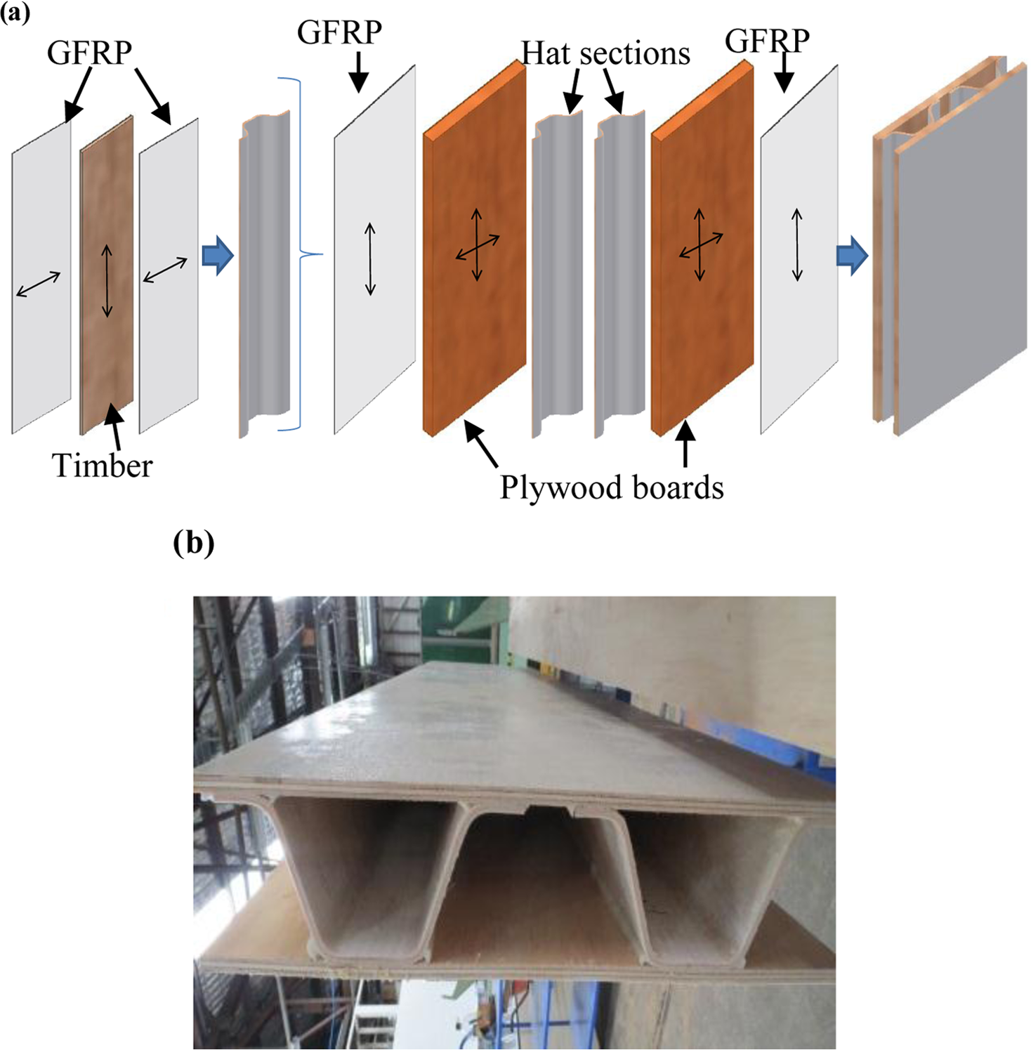
Sheathed FRP–timber wall panel: (a) fabrication process and (b) finished product.
Instrumentation and test set-up
Strain gauges were attached to both faces of the wall panels (i.e. faces A and B) at quarter and mid-height positions along lines L-L and R-R as indicated in Figure 3(a) to measure axial strains. The test specimens were loaded monotonically in axial compression until failure in a 1-MN capacity MTS testing machine. A loading plate and a support plate, both with a shallow rectangular grove, were used at the top and the bottom of the specimen as shown in Figure 3(b). A rectangular grove was used to avoid any horizontal slip at the top or bottom of the wall panel. A loading plate was fixed to the loading head of the MTS machine, while a bottom plate was fixed to the base of the MTS loading frame. The testing rig used for wall panel tests is shown in Figure 3(b). A 5-kN load was applied and then removed as the preloading step before the commencement of the formal testing process, during which the load and the axial shortening measurements were taken directly from the loading machine.
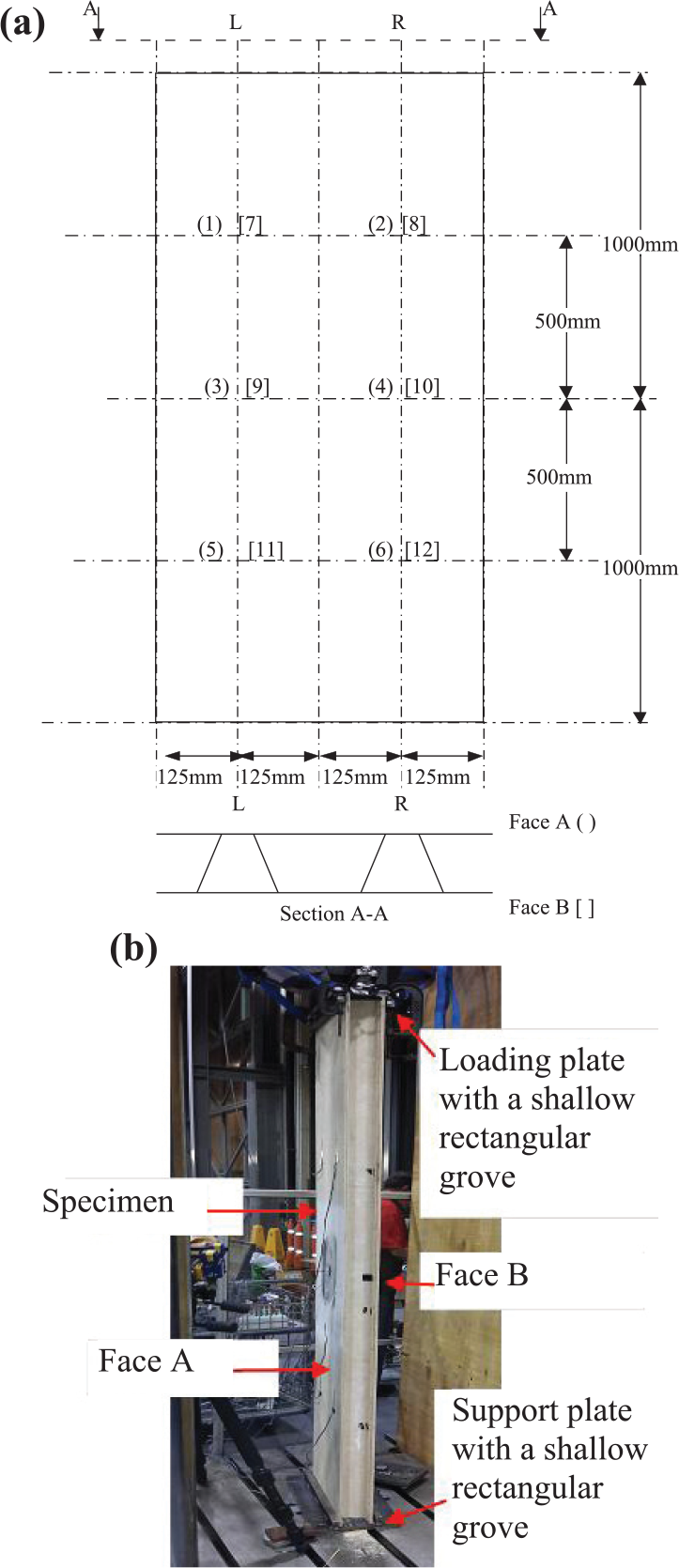
Instrumentation and test set-up: (a) strain gauge locations and (b) test rig.
Results and discussions
The specimens after failure and the load–axial shortening curves of the HFT and the pure timber wall panels are shown in Figure 4. The pure timber specimen failed due to the buckling of the wall panel, which was followed by the rupture of the hat section webs (Figure 4(a)). The HFT wall panel failed due to the buckling of the wall panel followed by the crushing of face B board of the wall panel (Figure 4(b)). The lateral displacements of both panels were towards face A of the panels. The HFT wall panel showed significant enhancement in axial stiffness, load-carrying capacity and deformation at failure over the pure timber wall panel (Figure 4(c)). The ultimate load reached by the pure timber wall panel was 106 kN, while that of the HFT wall panel was 203 kN. While the load-carrying capacity of the HFT wall panel is 91% higher than that of the pure timber wall panel, the material cost of the former is only around 40% higher than the latter based on rough estimates of costs in Queensland, Australia, implying significant cost savings.

Experimental behaviour of wall panels: (a) failure of pure timber wall panel, (b) failure of HFT wall panel and (c) load–axial shortening curves for both wall panels.
The axial strain distributions of faces A and B down lines L-L and R-R of the pure timber and the HFT wall panels are given in Figures 5 and 6, respectively. The face B strain gauge readings of locations ‘[7]’ and ‘[8]’ (Figure 3(a)) in the pure timber panel were not recorded due to a technical fault. Inspection of the strains in Figures 5(a) and 6(a) shows that at low loads, the strain distributions along L-L and R-R are uniform and the differences of strain readings between faces A and B are relatively small, which indicates relatively small lateral deformation of the face boards. For the pure timber panel under a load of 100 kN, the strain readings of face A are significantly different from those of face B (Figure 5(b)). At 100 kN load, the strain readings of face A also show significant variations down the height (Figure 5(b)). These observations can be attributed to the development of buckling deformation of the face boards. For the HFT wall panel under a load of 100 kN, the strain values (Figure 6(b)) are much smaller with reduced variations along L-L and R-R and reduced differences between faces A and B compared to those of the pure timber panel. The strain readings as well as the load–axial shortening curves (Figure 4(c)) indicate that the HFT panel had a substantially higher axial stiffness than that of the pure timber panel. At the ultimate load, the maximum strain value of the HFT panel (Figure 6(c)) is much higher than that of the pure timber panel (Figure 5(c)). This indicates that the addition of FRP enhanced not only the ultimate load but also the compressive strain at failure of the wall panel. At failure, the HFT panel also showed significant lateral deformation, which is obvious from the variations in strain readings along lines L-L and R-R and the differences in strain readings between faces A and B in Figure 6(c).
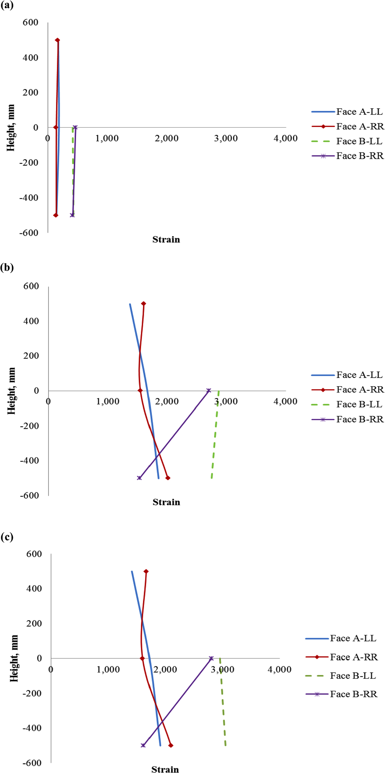
Axial strain distributions on faces A and B along lines L-L and R-R for pure timber wall panels: (a) 20 kN, (b) 100 kN and (c) 106 kN (ultimate load).
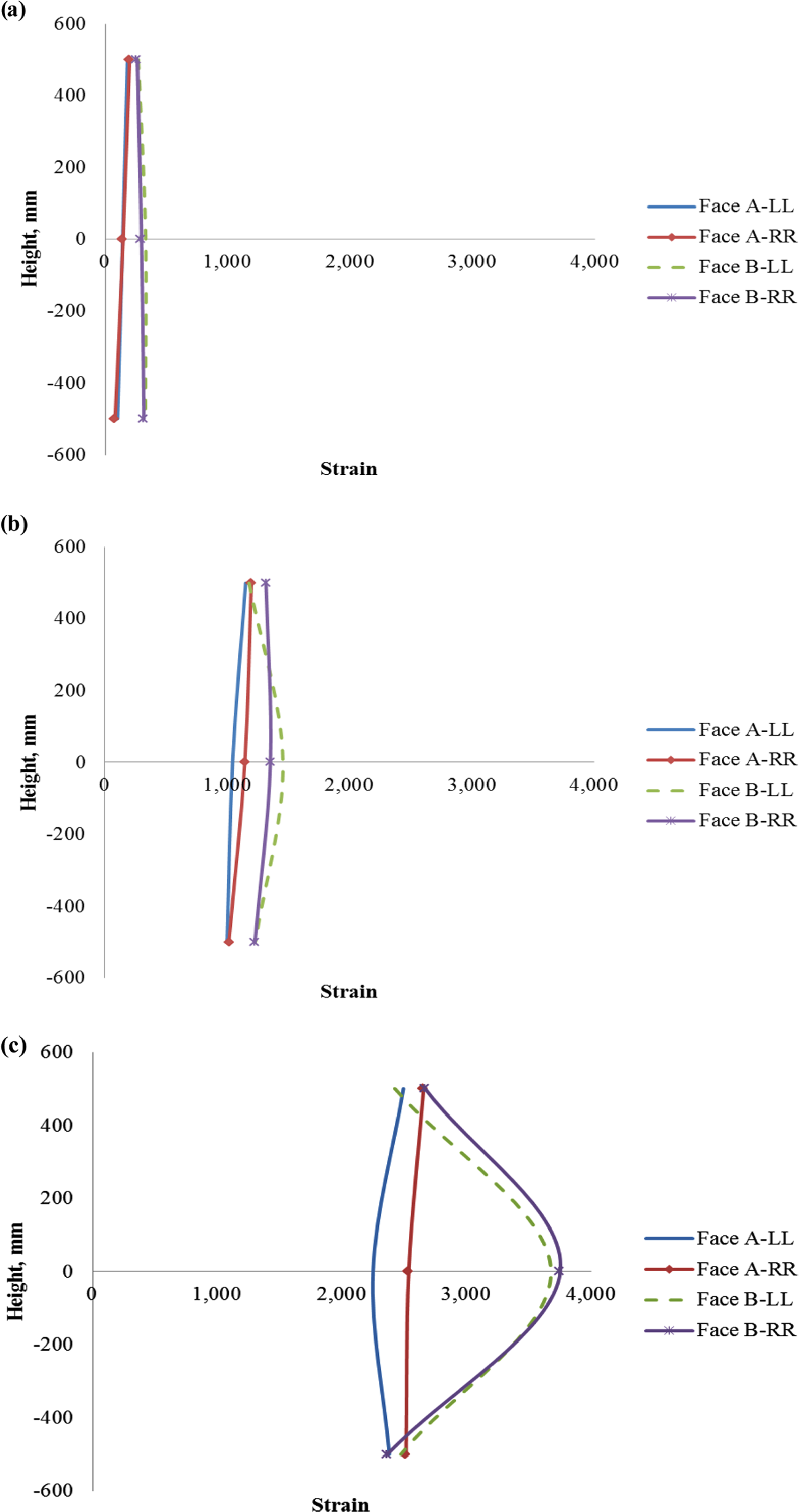
Axial strain distributions on faces A and B along lines L-L and R-R for HFT wall panels: (a) 20 kN, (b) 100 kN and (c) 203 kN (ultimate load).
Comparison with the sheathed cold-formed steel wall studs
Vieira and Schafer (2010) carried out a series of axial compression tests on sheathed wall studs. Their tests consisted of 1.6- and 2.4-m-long wall panels made of 362S162-68 (SSMA/ASTM nomenclature) cold-formed steel studs with either two 11.1-mm-thick oriented strand boards or 12.7-mm-thick Gypsum sheathing. The axial load-carrying capacity ranged between 80 and 100 kN per single stud while the load capacity per unit weight ranged between 2.78 and 10.9 kN/kg. The HFT wall panel presented in this study achieved an axial load-carrying capacity of 101.5 kN per stud, leading to a load capacity per unit weight of 13.84 kN/kg. Therefore, it is clear that while the axial load-carrying capacity of HFT wall panels is comparable to that of existing sheathed cold-formed steel stud wall systems, for the same load-carrying capacity, HFT wall panels are lighter than their sheathed steel stud wall counterparts.
Concluding remarks
This article has presented a new FRP–timber hybrid system called ‘hybrid FRP–timber (HFT) thin-walled structures’. HFT thin-walled structures are formed by combining thin FRP layers with timber veneers to create high-performance, lightweight and easy-to-construct structural members. These new products could be used in many applications such as load-bearing walls, roof structures, floor panels and bridge decks. The HFT system combines the orthotropic properties of timber and FRP in a complementary manner for highly efficient structural performance by orientating the fibre direction in the weak cross-grain direction of the timber veneer. These HFT sections can be manufactured using the simple compression moulding technique.
The HFT thin-walled sections proposed in this article are superior to the existing thin-walled timber sections both in terms of manufacturing effort and transverse material properties. In addition, HFT sections can also be manufactured in 3D complex geometries, thus allowing geometrical optimization to be realized for the best structural performance. To demonstrate the effectiveness of HFT thin-walled structures, a compression-moulded HFT wall panel and a pure timber wall panel were manufactured and tested under axial compression. The HFT wall panel significantly outperformed the pure timber wall panel in terms of both axial load-carrying capacity and ultimate deformation. In addition to the reduced volume of timber for the same load-carrying capacity, HFT structures are also expected to offer a significant economic advantage due to their ability to utilize low-quality timber and a relatively simple manufacturing process. A comparison of HFT wall panels with a typical sheathed cold-formed steel stud wall system revealed that while HFT wall panels could match the axial load-carrying capacities of steel stud wall systems, HFT wall systems can outperform the steel stud wall systems in terms of axial load-carrying capacity per unit weight.
Footnotes
Acknowledgements
The authors are grateful to Dr Henri Bailleres and Mr Rob McGavin of the Department of Agriculture and Fisheries Salisbury Research Centre for manufacturing the test specimens. The authors are also grateful for the financial support received from the Australian Research Council under the Discovery Early Career Researcher Award scheme to the first author (DE150101512).
Declaration of Conflicting Interests
The author(s) declared no potential conflicts of interest with respect to the research, authorship and/or publication of this article.
Funding
The author(s) disclosed receipt of the following financial support for the research, authorship, and/or publication of this article: The authors are grateful for the financial support received from the Australian Research Council under the Discovery Early Career Researcher Award scheme to the first author (DE150101512).