
Abstract
This article presents a new form of fibre-reinforced polymer-concrete-steel hybrid columns and demonstrates some of its expected advantages using results from an experimental study. These columns consist of a concrete-filled fibre-reinforced polymer tube that is internally reinforced with a high-strength steel tube and are referred to as hybrid double-tube concrete columns. The three components in hybrid double-tube concrete columns (i.e. the external fibre-reinforced polymer tube, the concrete infill and the internal high-strength steel tube) are combined in an optimal manner to deliver excellent short- and long-term performance. The experimental study included axial compression tests on eight hybrid double-tube concrete columns with a glass fibre–reinforced polymer external tube covering different glass fibre–reinforced polymer tube thicknesses and diameters as well as different high-strength steel tube diameters. The experimental results show that in hybrid double-tube concrete columns, the concrete is well confined by both the fibre-reinforced polymer tube and the high-strength steel tube, and the buckling of the high-strength steel tube is suppressed so that its high material strength can be effectively utilized, leading to excellent column performance. Due to the high yield stress of high-strength steel, the hoop stress developed to confine the core concrete is much higher than can be derived from a normal-strength steel tube, giving the use of high-strength steel in double-tube concrete columns an additional advantage.
Keywords
Introduction
High-strength steel (HSS) may be defined as steel with yield stresses of about 450 MPa and above. A major limiting factor for the structural use of HSS is the greater susceptibility of HSS members to buckling failure compared to their normal-strength counterparts. Therefore, when HSS with a yield stress around and above 700 MPa is used, the high material strength of HSS cannot be effectively utilized when loaded in compression, and the ductility of structural members can be greatly compromised. Against this background, a new column form has recently been proposed at The Hong Kong Polytechnic University (Teng and Yu, 2015). The new column form consists of a HSS tube inside a (normally concentric) fibre-reinforced polymer (FRP) tube, with the space inside the two tubes filled with normal-strength or high-strength concrete (Figure 1(a)). In addition to serving as the permanent formwork, the FRP tube is typically provided with fibres oriented close to the hoop direction to act as a confining tube that provides confinement to the concrete and shear resistance to the column. The HSS tube provides the ductile longitudinal steel reinforcement for the column and additional confinement to the core concrete inside the HSS tube. These columns, referred to as hybrid double-tube concrete columns (hybrid DTCCs or simply DTCCs) herein, have the following advantages over conventional concrete-encased HSS columns: (1) the confined concrete ensures the full utilization of the high material strength and ductility of HSS; (2) the use of a steel tube instead of a typical open section (Yu et al., 2016) leads to the enhanced confinement to the core concrete; (3) the FRP tube together with the ring concrete (the concrete between the FRP and the steel tube) protects the steel tube against corrosion; and (4) temporary formwork and steel reinforcing bars are both completely eliminated, thus simplifying the construction process. Indeed, the brittle responses of all three components (for HSS this is due to buckling) in a DTCC are suppressed by their interaction, resulting in a high-performance column that is highly resistant to both severe loadings (e.g. seismic loadings) and serve environments (e.g. marine environments).

Cross sections of (a) hybrid DTCCs and (b) hybrid DSTCs.
DTCCs may be seen as a variation of hybrid FRP-concrete-steel double-skin tubular columns (DSTCs) which consist an annular layer of concrete sandwiched between an outer FRP tube and an inner steel tube (Figure 1(b)). When DSTCs were first proposed, the filling of the inner void of a DSTC with concrete was already mentioned as a possibility to enhance column performance (Teng et al., 2007), and the effect of such filling on the seismic performance of a DSTC was studied by Zhang et al. (2015). Indeed, DTCCs are an attractive alternative to DSTCs when the column size needs to be minimized (e.g. maximize the usable floor area). DTCCs with a normal-strength steel tube have received some attention in the studies conducted by Ozbakkaloglu’s group (Fanggi and Ozbakkaloglu, 2015; Ozbakkaloglu, 2015; Ozbakkaloglu et al., 2016; Ozbakkaloglu and Fanggi 2013, 2015). However, none of these existing studies have examined the use of a HSS tube in DTCCs, although DTCCs are particularly attractive for use with a HSS tube. This is because the high susceptibility to local buckling of a thin HSS tube can be completely suppressed in a DTCC; in addition, as a HSS tube has not yielded when the axial stress of concrete is close to its unconfined concrete strength (when the dilation of concrete increases rapidly), it provides very effective confinement to the core concrete as an elastic tube during this stage of loading. This article, therefore, presents the results of the first series of axial compression tests on stub DTCCs with a HSS tube to demonstrate their excellent performance. The experimental setup and procedure are first described, followed by the presentation and interpretation of test results.
Experimental programme
Test specimens
In total, eight 600-mm-high hybrid DTCC specimens (Table 1) were tested, covering variations of the inner diameter (D) and actual (i.e. measured) thickness of the glass fibre–reinforced polymer (GFRP) tube and the outer diameter of the steel tube (ds). All the HSS tubes had the same thickness of 6 mm. Two concrete-filled steel tubes (CFSTs) and three hollow HSS tubes (HSTs) were also tested for comparison purposes. The results of the CFST specimens are, however, not discussed in the article as they had a significantly higher concrete strength than the DTCC specimens, making comparisons cumbersome. The DTCCs are named with the following parts: the letter ‘D’ to denote a DTCC, the number of layers in the GFRP tube, the inner diameter of the GFRP tube in mm, the outer diameter of the steel tube in mm and the identifier for nominally identical specimens.
Details of DTCC specimens.
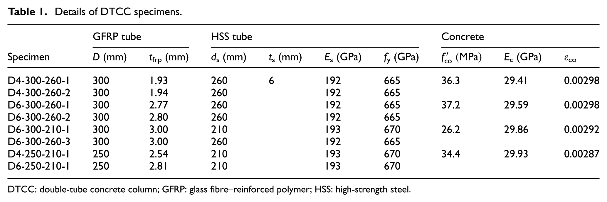
DTCC: double-tube concrete column; GFRP: glass fibre–reinforced polymer; HSS: high-strength steel.
The HSS tubes used in this study were cold-rolled and electric-resistance welded from HSS plates. The GFRP tubes were manufactured by filament winding with fibres at ±80° to the longitudinal axis. The DTCC specimens were carefully prepared to ensure flat ends and concentricity between the two tubes. A 50-mm-wide carbon fibre–reinforced polymer (CFRP) strip was wrapped at each end of a DTCC specimen to avoid premature local failure there.
Material properties
GFRP tubes
Filament-wound GFRP tubes of two thicknesses (or types) were used in the tests: those with four layers (or plies) and six layers of fibres, respectively, with each layer having a nominal thickness of 0.42 mm based on the weight of fibres according to the manufacturer. The novel curved coupon test, which was recently proposed by the authors’ group (Teng et al., in preparation), was used to obtain the elastic moduli of the GFRP tubes in the hoop direction. In the curved coupon test, a curved coupon cut from a circular GFRP tube is directly pulled at the two ends, and the instrumentation of the curved coupon was generally in accordance with ASTM D3039/D3039M:2002 (2002). Six curved coupons, each with a width of 35 mm and a gauge length of 150 mm, were tested to determine the elastic modulus for each type of GFRP tubes. The elastic modulus values for individual coupons were obtained based on the actual thickness ranged from 35.6 to 37.3 GPa except one specimen, which had a significantly larger value of 39.8 GPa and was excluded in calculating the average values. As the measured thicknesses differed significantly for tubes of the same nominal thickness, it was expected that the elastic modulus values would also differ accordingly when calculated on the basis of measured thickness. However, the experimental values of elastic modulus for all coupons were very close to each other, which seems to suggest that the fibre volume per layer was not constant. The average hoop elastic moduli based on the actual thickness so obtained from the curved coupon tests are 36.3 and 36.2 GPa for the six-ply tubes and the four-ply tubes, respectively. The average Poisson’s ratio in the hoop direction from two four-ply curved coupons is 0.31.
Axial compression tests on short GFRP tubes (rings) were also conducted following the Chinese standard GB/T5350-2005:2005 (2005) to obtain the axial elastic modulus of GFRP tubes. For half of the ring specimens, strain gauges were attached to both the outer and the inner surfaces to evaluate the influence of bending. In general, the strain readings from the inner surface are smaller than those from the outer surface due to outward bending of the GFRP tube, but the differences are relatively small compared to the absolute values of the strain readings and are ignored in this study. The axial stress–strain curves were basically linear until the final stage, and the elastic modulus values (Efrp,a) were obtained from the strain data between 1000 and 3000 micro-strains following ASTM D3039/D3039M:2002 (2002). The average elastic moduli in the axial direction for the six-ply and four-ply GFRP tubes were 10.3 and 11.5 GPa, respectively, and the corresponding Poisson’s ratios are 0.133 and 0.121, respectively.
HSS tubes
In this study, circular HSS tubes of Chinese steel grade Q690 (with a nominal yield stress of 690 MPa) were employed in the tests. Two HSS tubes (one with a diameter of 260 mm and one with a diameter of 210 mm) were used in the tensile tests in accordance with BS 18:1987 (1987), with five coupons for each tube cut from areas away from the weld. The average values of elastic modulus, yield stress and Poisson’s ratio were found to be 192 GPa, 665 MPa and 0.26 for the HSS tube with a diameter of 260 mm, and 193 GPa, 670 MPa and 0.27 for the HSS tube with a diameter of 210 mm. The yield stresses from these tests were later found to be underestimates as an initial tensile force was introduced into the coupon tests but this initial tensile force was initialized out of the recorded test data. Three Q690 HSTs having the same height as the DTCC specimens (i.e. 600 mm) were also tested to determine their mechanical response under axial compression. Strain gauges and linear variable displacement transducers (LVDTs) were installed on HSTs with the same layout as that in the DTCC specimens (see Figure 2). The compression test results are given in Table 2. The average ultimate stress of HST-260-1 and HST-260-2 is 733 MPa, while the stresses from the corresponding coupon tests at the same axial strain level are around 700 MPa, confirming the underestimation of the tensile coupon tests. Specimen HST-210 after compression test is shown in Figure 3, and an obvious local buckle is seen near one end.
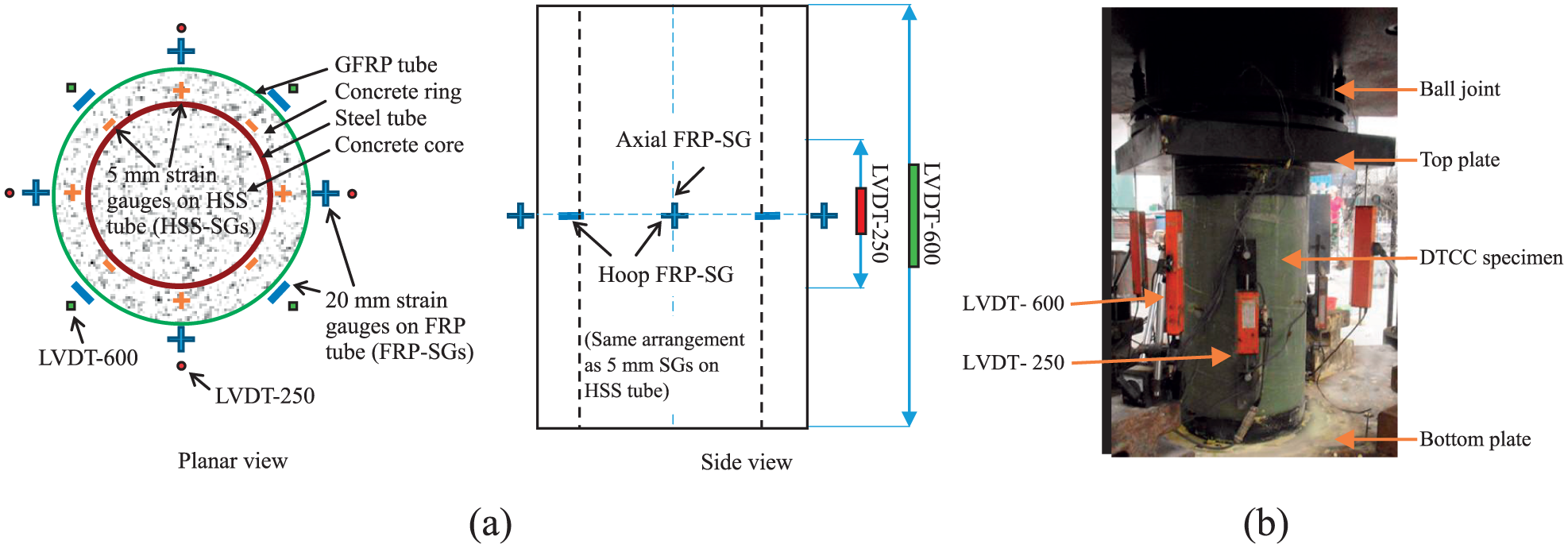
Experimental setup and instrumentation for DTCCs: (a) layout of strain gauges and LVDTs and (b) experimental setup.
Key test results of Q690 hollow steel tubes.

LVDT: linear variable displacement transducer.

Hollow steel tube after compression test (diameter ds = 210 mm).
Concrete
The concrete of the DTCC specimens was cast in four batches as shown in Table 1. Concrete cylinder tests were conducted for each batch of concrete to determine the material properties. As the eight DTCCs presented in this article were part of a larger experimental programme that included DTCCs tested under cyclic loading, the testing of each batch of specimens took about 10 days. For each batch of concrete, nine cylinders were tested at three times during the testing period to measure the strength growth of concrete, but comparison of the cylinder tests showed insignificant changes in material properties. The elastic modulus
Experimental setup
The experimental setup is presented in Figure 2. Twelve strain gauges (SGs) (four in the axial direction and eight in the hoop direction), all with a gauge length of 20 mm, were installed on the outer surface of the FRP tube (FRP-SGs) of each specimen; they were evenly distributed around the circumference as shown in Figure 2(a). Another 12 strain gauges with a gauge length of 5 mm were installed on the outer surface of the HSS tube of each specimen (HSS-SGs), following the same layout as that of the FRP-SGs. In addition, eight LVDTs were installed on each specimen: four to measure axial shortenings over the full-length of the specimen (LVDTs-600) and another four to measure axial shortenings over the 250-mm mid-height region (LVDTs-250) (Figure 2(a)). The in-filled concrete of all the specimens was cured for at least 28 days before the testing of DTCC specimens. Both ends of the DTCC specimens were sanded prior to the application of a thin layer of high-strength gypsum, and all the DTCC specimens in this study were loaded on the entire cross section. The column tests were all conducted using a 1000-t machine with displacement control at a rate of 0.5 mm per minute.
Experimental results and discussion
Failure process of DTCCs
The failure process of all the DTCC specimens was dominated by the hoop tensile rupture of the external FRP tube near the mid-height after significant cracking on the FRP tube generally in the fibre directions (e.g. specimen D6-300-260-2 in Figure 4(a)), and the final failure was accompanied with loud noises. The test of specimen D6-300-260-1 was terminated by the machine automatically before the rupture of FRP tube, when the load was close to the capacity of the testing machine. After the test, the FRP tube of each specimen was removed to expose the ring concrete, which was found to have experienced crushing near the mid-height (Figure 4(b)). All the HSS tubes of the DTCCs were taken out for examination, and no significant buckling deformation was observed (e.g. Figure 4(c)), which suggests that the FRP tube together with the concrete provided effective restraint to the HSS tube against local buckling.
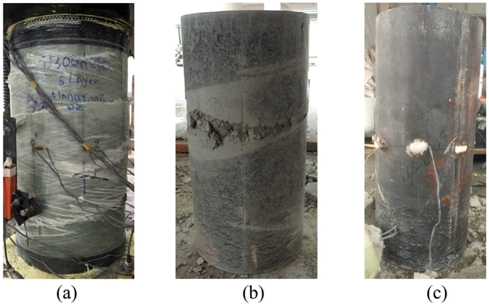
Specimen D6-300-260-2 after test: (a) specimen after test, (b) ring concrete and (c) HSS tube.
Load–strain behaviour of DTCCs
During each test, the key data of the specimen, including the axial loads P, the axial strains
Key test results of DTCC specimens.
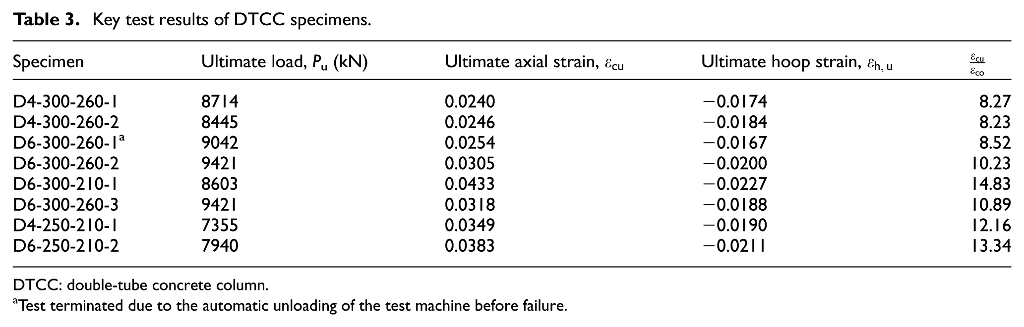
DTCC: double-tube concrete column.
Test terminated due to the automatic unloading of the test machine before failure.
The axial load–strain curves of all the specimens are shown in Figure 5, which are seen to be bilinear with a monotonically ascending second branch, indicating excellent deformability and ductility. The curves of specimens D6-300-260-1 or D6-300-260-2, with a thicker FRP tube, have a slightly steeper and longer second branch than those of D4-300-260-1 or D6-300-260-2. The same observation can be made about specimens D4-250-210-1 and D6-250-210-1 (Figure 5(b)). Specimen D6-300-260-3 had the same section as D6-300-260-1 and D6-300-260-2 but a significantly lower concrete strength, but the three D6-300-260 specimens still showed similar behaviour, indicating that the column behaviour, due to confinement, is not sensitive to such a change in concrete strength. Figure 5(b) also shows that an increase in the diameter of the HSS tube from 210 mm in specimen D6-300-210-1 to 260 mm in specimen D6-300-260-3 substantially enhances the ultimate load of DTCC, which is however accompanied by a significant decrease in the ultimate strain from 0.0433 to 0.0318. A comparison of the two specimens with a 210 mm HSS tube (i.e. specimens D4-250-210-1 and D6-250-210-1) shows that as the FRP tube becomes thinner, the ultimate load and the ultimate axial strain both decrease accordingly (Figure 5(b)).
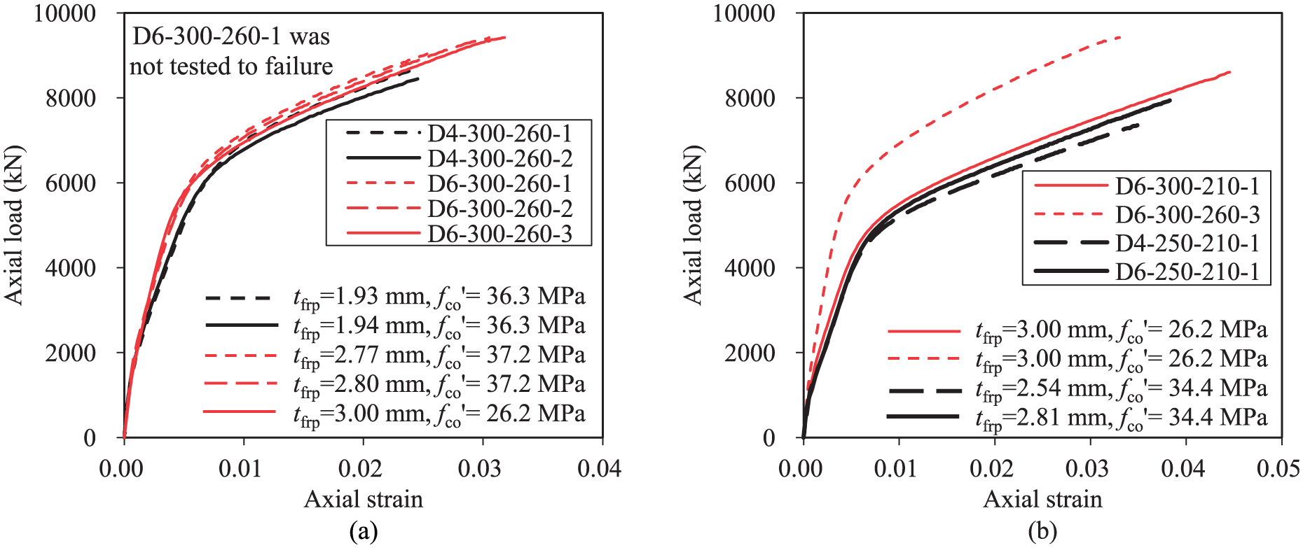
Axial load–strain curves.
Axial strain compatibility between the HSS tube and the FRP tube
Figure 6 presents comparisons of average axial strains from the axial FRP-SGs, the axial HSS-SGs or the LVDTs (i.e. LVDTs-250 and LVDTs-600) for specimens D4-300-260-1 and D6-300-260-3, respectively. The axial strains from FRP-SGs, LVDTs-600 and LVDTs-250 are in close agreement, which is also true for all eight specimens. Figure 6(a) shows that the average axial strains from HSS-SGs are smaller than those from other axial strain measurements during the initial stage, but the trend is reversed during the later stage, indicating that some slips existed between the HSS tube and the ring concrete. The same phenomenon of trend reversing was found in all other DTCC specimens with a four-ply FRP tube. It may be concluded that a sufficiently stiff FRP tube is needed to ensure that axial deformation of the HSS tube is in full synchrony with that of the ring concrete during the entire loading process as otherwise some bending deformation of the HSS tube or slips between the HSS tube and the concrete can be expected in DTCCs.

Axial strains from different measurements: (a) D4-300-260-1 and (b) D6-300-260-3.
Lateral dilation behaviour of DTCCs
The lateral dilation behaviour of DTCCs can be characterized by the axial strain–hoop strain curves (i.e. dilation curves). For each DTCC specimens, two dilation curves, one obtained from the FRP tube and one obtained from the HSS tube, can be compared to see if their dilation responses are similar. The dilation curves for the same two specimens as discussed above are shown in Figure 7, and they were derived as follows: the hoop strains were averaged from the readings of hoop FRP-SGs (curve ‘FRP’) and hoop HSS-SGs (curve ‘HSS’), respectively, while the corresponding axial strains were averaged from LVDTs-250 and axial HSS-SGs, respectively. A gap is seen to develop between the two dilation curves for specimen D4-300-260-1 as the axial strain increases (Figure 7(a)), suggesting that the FRP tube and the HSS tube experienced different lateral dilations and the concrete ring was subjected to non-uniform confinement. The dilation behaviour of most of the other DTCC specimens is similar although the difference between the two dilations curves is smaller than that seen in Figure 7(a). Figure 7(b) shows a different situation: with a stronger GFRP tube and weaker concrete, the dilation behaviour becomes more uniform, indicating that the ring concrete is under almost uniform confinement.

Hoop strain–axial strain curves in a DTCC: (a) D4-300-260-1 and (b) D6-300-260-3.
Development of stresses in the HSS tube
Figure 8 shows how the biaxial stress state varies in the HSS tube in a DTCC for each of the same two DTCC specimens. The stress increments in the HSS tube for given strain increments were found using the average strains on the HSS tube and constitutive law of HSS which is assumed to be an elastic–plastic material with strain hardening and governed by the J2 flow theory (Chen and Han, 2007). These stresses were determined in an incremental manner: measured axial and hoop strain increments averaged from the strain gauges were used to find stress increments and thus the total stresses. It is important to note that a significant hoop tensile stress developed in the HSS tube in both specimens before the HSS reached yielding, but this stress started to reduce over a substantial range of axial strain after yielding, before it started to increase again at a much lower rate (Figure 8). The much higher yield strain of HSS led to a substantially larger confining stress to the core concrete than a normal-strength steel tube. Furthermore, the axial stresses in the HSS tube indicate that the high material strength of the HSS was fully utilized, leading to very ductile axial response without any detectable effect of local buckling. It can be deduced that steels of even higher strength (e.g. over 1000 MPa) can be fully utilized in such DTCCs if a sufficiently stiff FRP confining tube is present.

Stresses in the HSS tube of a DTCC: (a) D4-300-260-1 and (b) D6-300-260-3.
Mechanisms of beneficial interaction
In Figure 9, the axial load–strain curves of the same two representative DTCC specimens are each shown against five other axial load–strain curves: (1) a curve from specimen HST-260-1 (‘HST alone’), (2) a curve from specimen HST-260-1 with the post-buckling response replaced by a curve parallel to the hardening curve of a representative HSS tensile coupon test (‘HSS coupon’), (3) a curve for the FRP-confined concrete (FCC) alone predicted Jiang and Teng’s (2007) model but with the FRP tube approximated as an FRP wrap with the axial stiffness ignored (‘FCC alone’), (4) the sum of (1) and (3) (Sum-HST) and (5) the sum of (2) and (3) (Sum-coupon). It should be noted that in making predictions for Figure 9(a), the axial strain differences between the HSS tube and the FRP tube were taken into account as otherwise the predicted initial stiffness will be significantly larger than the test result. The axial resistance of the FRP tube (estimated to be around 500 kN at the maximum) is ignored as it is small and it is probably mostly lost at higher axial strains where extensive hoop cracking has developed. As the three hollow steel tube tests were terminated at an axial strain lower than the ultimate axial strain of DTCCs, the axial load–strain curve of the steel tube alone beyond this strain value was extrapolated from the experimental curve of specimen HST-260-1 via an exponential extension to enable direct comparisons. The extended portion of the axial load–strain curve of the steel tube alone is clearly indicated in Figure 9. In making the predictions for the FCC for each DTCC, the effect of Poisson’s ratio on the hoop strain in the FRP tube, which is likely to have disappeared after extensive cracking in the FRP tube, is ignored, so the FRP tube was treated as a confining tube with stiffness only in the hoop direction. In Figure 9, the predicted curves for each DTCC terminate at the experimental ultimate axial strain of the DTCC for ease of comparison.

Components of axial load resistance in a DTCC: (a) D4-300-260-1 and (b) D6-300-260-3.
It is evident from Figure 9 that the curve of a DTCC specimen is much higher than the corresponding curve of Sum-HST in the post-buckling stage of hollow steel tube, suggesting that the performance of a DTCC specimen is far superior to what could be expected if there were no interaction between the steel tube and the concrete due to the suppression of local buckling of the HSS tube in a DTCC. At failure by the hoop tensile rupture of the FRP tube, the load resisted by the DTCC exceeds the sum of HST and FCC by an average of 38.6% for the two identical D4-300-260-1/2 specimens and an average of 42.8% for the two identical D6-300-260-1/2 specimens.
Moreover, even if the effect of local buckling of HSS tube is eliminated, the combined resistance of the HSS tube and the FCC (Sum-coupon) is still significantly lower than the test result, especially for specimens with a six-ply FRP tube (Figure 9). This underestimation suggests that the interaction between HSS tube and concrete is highly beneficial to the load-carrying capacity of DTCCs. A significant hoop stress in the HSS tube has two consequences: it reduces the axial stress that can be carried by the HSS tube but increases the axial stress can be carried by the FCC. The beneficial effect of interaction arises because the axial load resistance from the latter is significantly larger than that from the former.
Conclusion
This article has presented a new form of hybrid columns made of FRP, HSS and concrete and the first series of tests on such columns to demonstrate their excellent performance. The new column form, referred to as DTCCs, consists of a HSS tube inside an FRP tube, with all the space within the two tubes filled with concrete. Obviously, the column section configuration can vary depending on needs: the HSS tube may be eccentrically placed to the FRP tube and the shapes of the two tubes do not have to be circular. This study has been concerned with the basic configuration having two concentrically located circular tubes.
Based on the results and discussion presented in this article, the following conclusions can be drawn for these hybrid DTCCs with a sufficiently stiff FRP tube that ensures a monotonically ascending second branch for the confined concrete in DTCCs:
Hybrid DTCCs with a HSS tube possess a bilinear axial load–strain curve, displaying excellent ductility. Failure of DTCCs is by the rupture of FRP tube due to hoop tension.
Local buckling of the HSS tube can be fully suppressed, so the HSS tube exhibits excellent ductility without any detectable effect of local buckling.
The high material strength of HSS is fully utilized by the development of both tensile stresses in the hoop direction and compressive stresses in the axial direction. Due to the high yield stress of HSS, the hoop stress developed to confine the core concrete is much higher than can be derived from a normal-strength steel tube.
A DTCC can be viewed as the insertion of an HSS tube in a concrete-filled FRP tube, but the ultimate load of a DTCC specimen is much larger (i.e. by at least 37% for the present DTCC specimens) than the combined axial resistance of the HST and the concrete-filled FRP tube, illustrating the great benefit of interaction between the HSS tube and the confined concrete.
The ultimate load of a DTCC specimen can even be much larger than the combined axial resistance of the HST without the effect of buckling and the concrete-filled FRP tube. In a DTCC, some of the HSS material capacity is used to confine the core concrete, and the increase in the axial load resistance derived from the confining action of the HSS tube far exceeds the resulting reduction in axial load resistance of the HSS tube.
Footnotes
Acknowledgements
The authors are grateful to Drs Wei Qiu and Guan Lin for their helpful comments during the preparation of the manuscript.
Declaration of Conflicting Interests
The author(s) declared no potential conflicts of interest with respect to the research, authorship and/or publication of this article.
Funding
The author(s) disclosed receipt of the following financial support for the research, authorship and/or publication of this article: This work was supported by the Hong Kong Research Grants Council (Project Reference Number: PolyU 152153/14E) and The Hong Kong Polytechnic University (Project Account Code: G-SB02).