
Abstract
This article contains original works of testing and numerical validation on section bending resistance of new innovative built-up thin-walled metal Hybrid Double-I-Box Beam sections when subjected to local buckling. The cross section of Hybrid Double-I-Box Beam section is distinctive, which has advantages of both an ‘I’ section and a closed-box section. A total of 24 sections in three series that includes 8 homogeneous sections and 16 hybrid sections were tested under four-point bending. The varying parameters considered in the test specimens were as follows: first, hybrid parameter ratio, that is, yield strengths of flange steel to web steel (Φh = fyf/fyw); second, the ratio of breadth to the overall depth (B/D) of the section; and third, the flange thickness (tf). The moment-resisting capacity of these built-up sections are high due to the presence of more material at the flanges. The closed box-web portion provides higher torsional rigidity. From the test results, it was found that the hybrid sections have higher bending resistance capacity than the homogeneous sections, so technically gains more strength to weight. The increase in B/D ratio gained the increase in both major and minor axis bending resistance. The intermediate flange stiffener which alters the flange plate slenderness (λpf) had a significant effect on the local buckling resistance of the flange plate. Verification of numerical models followed by a parametric study was undertaken using ABAQUS finite element analysis software. The test results obtained were compared with the predicted design moment of resistance (Mc,Rd) as per Eurocode design standards EN 1993-1-3: 2006-Design of Steel Structures for Cold-Formed Steel Members and Sheeting and the adequacy is confirmed.
Keywords
Introduction
The structural consideration for using thin-walled cold-formed steel (CFS) is due to the growing demand for high strength to low weight of the structural member of significance, to serve the intended purpose. Nowadays, applications of built-up CFS sections are growing in popularity in North America, Europe and Canada and also in many developing countries. The CFS sheets can be formed into any required geometrical shape and it can be used either as a single section or fastened together into an assembly. There are many grades from low tensile to high tensile structural steel sheets that are manufactured and they are available in the market. A hybrid girder is a beam that has different grades of steel in flanges and webs. In this study, it is implemented such that the flanges have higher strength than the web. Eurocode 3-1-3 mentions the term hybrid girders and gives a limitation that the ratio of basic yield strength of the flanges to the yield strength of the webs should not exceed 2.
In the present investigation, built-up CFS Double-I-Box Beam (DIBB) section consists of four parts assembled into a single unit. The flange is a plain channel with a single intermediate stiffener. The web is in form of a lipped channel section. The channels are fastened together using bolted connections (M6-10.9 grade hexagonal head bolts). In the homogeneous DIBB sections, both webs and flanges are made of same grade of low tensile steel plates. And in the Hybrid Double-I-Box Beam (HDIBB) sections, webs are made of low tensile steel plates and the flanges are made up of either medium tensile or high tensile steel plates. In the new DIBBs and HDIBBs, the average shape factor is 1.17, that is, equivalent to an ‘I’ section and also it has a closed box-web portion which offers higher resistance to lateral-torsional buckling. The slenderness of plate elements forming the various parts of the HDIBB sections are classified according to EN 1993-1-3 (2006), and EN 1993-1-1 (2005) as Non-Compact/Class-3 sections and Slender/Class-4 sections.
Research background
Current design standards do not deal with the design of built-up closed-form CFS members, so there is a need for more research to know the structural behaviour of these sections. Some of the previous literatures which are taken as references in relevance to the present investigation have been briefed below.
Wang and Young (2017) performed a numerical investigation on CFS built-up section beams with perforated webs. They found that the influence of web holes on the beam strengths was more significant for beams with built-up closed sections than beams with built-up open sections. Li et al. (2016) conducted four-point bending tests and investigated the in-plane behaviour of cold-formed, thin-walled built-up box beams, which consists of nested C and U sections. They found that at mid-span of the cross section, the components in built-up box beams can resist the bending moment integrally. It was also concluded that the moment capacity of built-up box beams bending about strong axis is suggested to be taken as 90% of the capacity summation of individual components. Tondini and Morbioli (2015) did experimental and numerical study on cold-formed laterally restrained steel rectangular hollow flanges beams (RHFBs) to investigate their flexural capacity. They found that the flexural behaviour of RHFB specimens was influenced by variation in yield strength between the tubes and the web. Local buckling and plastic behaviour was induced in the web. It was also reported that the insertion of an intermediate stiffener in the external plates of the hollow flanges was beneficial for increasing the local buckling critical load of the plate. Wang and Young (2015) performed finite element analysis (FEA) to investigate the bending strength of built-up box sections used in residential and commercial construction in North America. They concluded that the built-up closed-form cold-formed sections do possess higher torsional rigidity and the design equations predicted by modified DSM in AISI 2012 code was overconservative for closed-form sections. Xu et al. (2009) conducted FEA to investigate the bending strength of built-up box sections used in residential and commercial construction. It was concluded that it is appropriate that for normal loading conditions, the flexural strength of CFS built-up box section is considered as the algebraic sum of nominal flexural strengths of the individual parts as predicted in the design aids. And for eccentric loading, the basic assumption was found unsatisfactory. It recommends a modification factor of 0.9 to be applied for eccentric loading. Shokouhian and Shi (2015) concluded that hybrid sections had higher strength compared to homogeneous sections, and the advantage of ‘I’ section is that it offers more bending resistance for less cross-sectional area. It can also support high longitudinal shear stress. Laím et al. (2013) did a research study on experimental and numerical investigation into the behaviour of CFS and concluded that compared to open mono-symmetric sections built-up closed-form sections have more strength to weight. They also concluded that open sections fail due to lateral-torsional buckling failures, whereas closed sections failed due to distortional buckling. Zhou and Shi (2011) did research on built-up I-beams and found that the grade of steel, flange slenderness ratio and effective width-to-thickness ratio of compression flanges considerably affect the flexural strength capacity of the beams. Veljkovic and Johansson (2004) stated that high-strength steel (HSS) sections are used when there is a structural demand. Whenever the depth of web is restricted, then HSS is very effective and essential. From the literature, it is clear that there were only few research works done on hybrid and closed-form built-up sections. The wide-ranging application of hybrid girders and built-up sections in the construction industry would require more research and also necessitates inclusion of design rules in codes or handbooks, and this research was intended to support in that aspect.
In this research, experiments were conducted on local buckling and yielding capacities of short-span DIBBs and HDIBBs under four-point bending. The non-linear FEA was performed using ABAQUS software, and the numerical results were verified and validated against the test results. Parametric studies were performed for ideal finite element (FE) HDIBBs models made of structural materials recommended in EN 1993-1-3. A series of conclusions based on the experimental tests and parametric studies were summarized. The fabricated test specimens and the cross-section form of HDIBB sections with varying B/D ratios are shown in Figure 1.
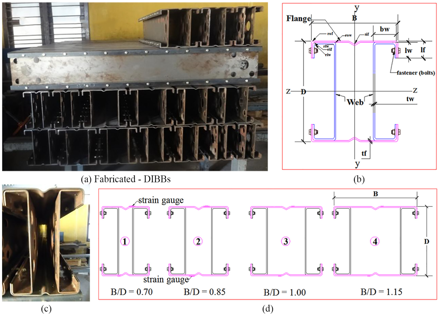
Hybrid Double-I-Box Beam (HDIBB) sections: (a) Fabricated- HDIBB sections, (b) Parts of a HDIBBS section, (c) Actual cross-section and (d) Varying B/D ratios.
Experimental investigation
The experimental tests on built-up CFS HDIBB sections were conducted in the Advanced Structural Engineering Laboratory of Easwari Engineering College in Chennai, India. The unique test set-up was specially fabricated to conduct four-point bending tests on short-span beams.
Test specimens
Three series of tests with different Φh = fyf/fyw ratios were conducted. Each series consists of eight specimens with varying B/D ratios and two different thicknesses of the flange plates (tf).
Series 1 comprises thin-walled homogeneous DIBB sections. In these built-up sections, both the flanges and the webs were fabricated of same-grade low tensile strength steel sheets (i.e. LT-LT). Series 2 and Series 3 comprise HDIBB sections in which the flanges are made of medium tensile or high tensile strength steel sheets and webs are made up of low tensile strength steel sheets (i.e. MT-LT and HT-LT). The thickness of the webs (tw) is 2.5 mm for all the specimens, whereas the thickness of the flanges (tf) varies as 2.5 and 3.0 mm which are designated as A and B in the specimen id, respectively. The B/D ratio (0.70, 0.85, 1.00 and 1.15) of each beam is specified at the end of the nomenclature of the specimens.
The beam dimensions were precisely measured using a digital vernier calliper and the thickness of sheet was taken as specified by the manufacturer. The outer radius (rof) of corners is equal to twice the thickness (2tp) for flanges. The flange channel consists of an intermediate stiffener (sif) that has a radius equal to three times the thickness of flange plate (3tf). The outer web corner radius (row) is equal to inner flange corner radius (rif). Table 1 presents the mass, measured dimensions, B/D ratio, hybrid parameter, flange plate slenderness, section properties, torsion constant and shape factor of the prepared specimens.
Measured dimensions and section properties of DIBB and HDIBB sections.
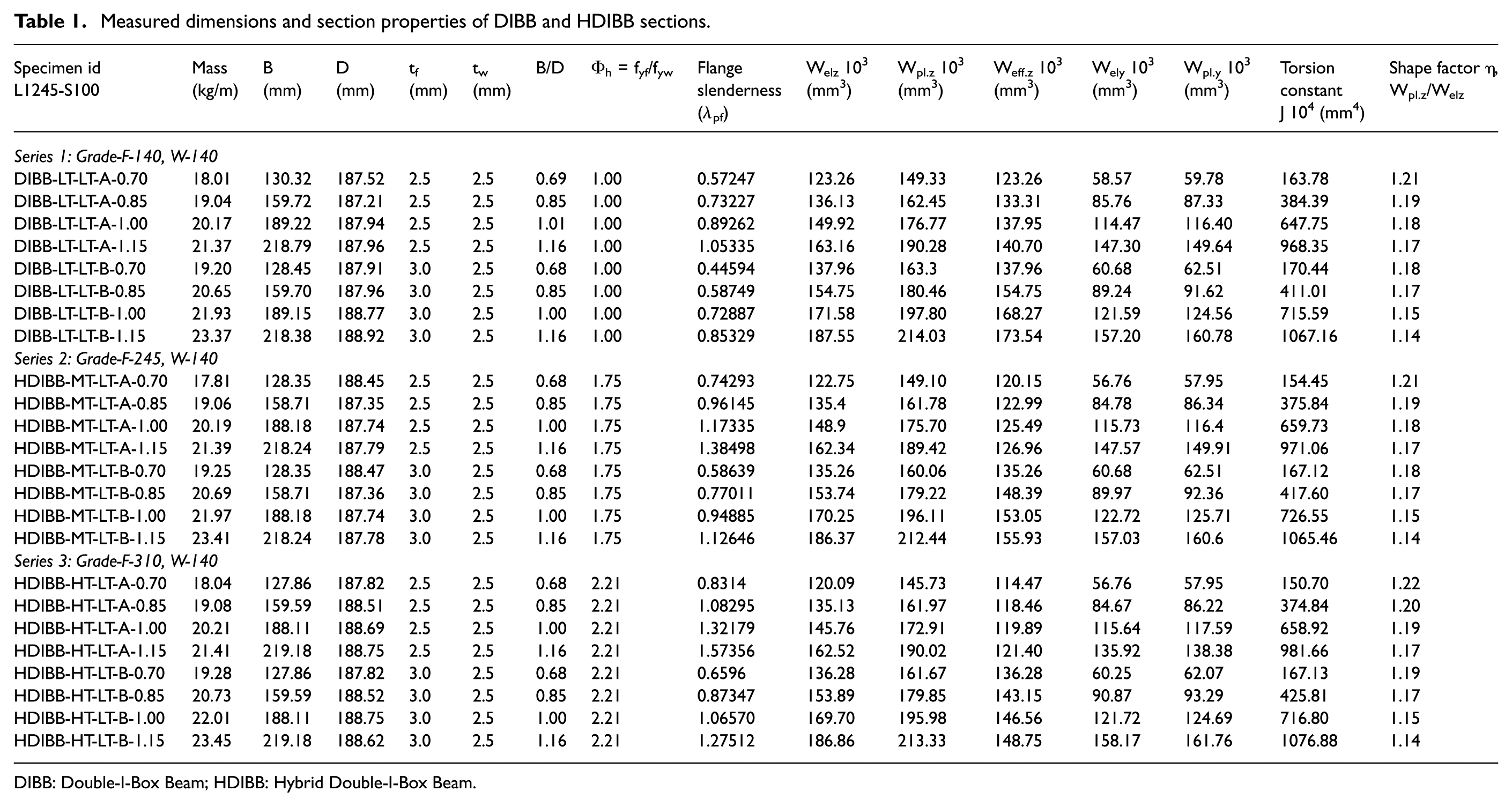
DIBB: Double-I-Box Beam; HDIBB: Hybrid Double-I-Box Beam.
Mechanical properties
In the built-up hybrid beams, various grades of materials are used, so it is essential to obtain their accurate stress–strain relationship and their basic mechanical properties. A total of 26 coupons were tested to determine the mechanical properties of the different grades of steel used in forming these sections. From the stress–strain curves and properties, we can predict the section moment capacities of the built-up sections.
All the tensile coupons are prepared and tested according to EN ISO 6982-1 (2009) International standards in displacement control method. The uniform cross head displacement rate applied is 0.01 mm/s. The tests were performed using Zwick/Roell Z100 kN Electro-mechanical testing machine. The coupons were extracted from plain steel sheets and also from the press-braked channels including all grades and thicknesses. The larger the size of the coupons (parallel length and width), the greater the precision. It was easier to cut and extract large size flat coupons from sheets. While cutting coupons from the flanges and webs of formed profiles, it was tuff to machine and extract large size flat coupons, hence smaller size coupons were cut-out for that reason. The sizing of coupons is within the recommended limits in the standards (EN ISO 6982-1 (2009)) as shown in Table 2. The width (b0 = 50 mm for sheet cut coupons and b0 = 30 mm for coupons cut from channels) was proportionate to the gripped end widths (b = 30 mm for sheet cut coupons and b = 15 mm for coupons cut from channels).
Sizing of tensile coupons (as per EN ISO 6982-1, 2009).
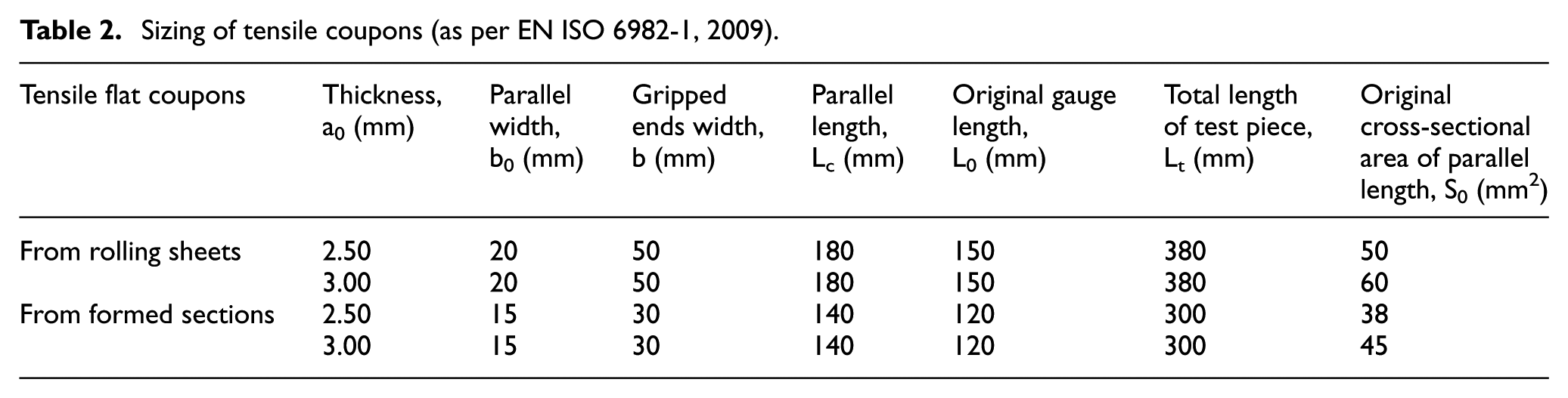
Figure 2 shows the preparations of coupons and the tensile testing process. Table 3 summarizes the tensile coupons test results of steel used. Figure 3 shows the graphical representation of engineering stress–strain relationship of various grade steel coupons cut from the channels. Tensile test results show that the measured stresses at yield point (fy) and ultimate (fu) exceeds the nominal basic yield stresses (fyb) and basic ultimate stresses (fu) as specified by EN 3-1-3 (i.e. fyb/fub are Grade-140/270 MPa, Grade-245/380 MPa and Grade-310/450 MPa) for Cold-Rolled Low Tensile (CRLT), Hot-Rolled Medium Tensile (HRMT) and Hot-Rolled High Tensile (HRHT) classes of steel sheets, respectively. The properties differed depending on the thickness, portion of the longitudinal cut of coupons from the elements and the amount of cold work done during press-braking operation in the fabrication of channels.

Coupons preparation and tensile testing: (a) Tensile Coupons, (b) Measuring, (c) During testing and (d) Failure of a coupon.
Mechanical properties of steel materials used in HDIBB sections.
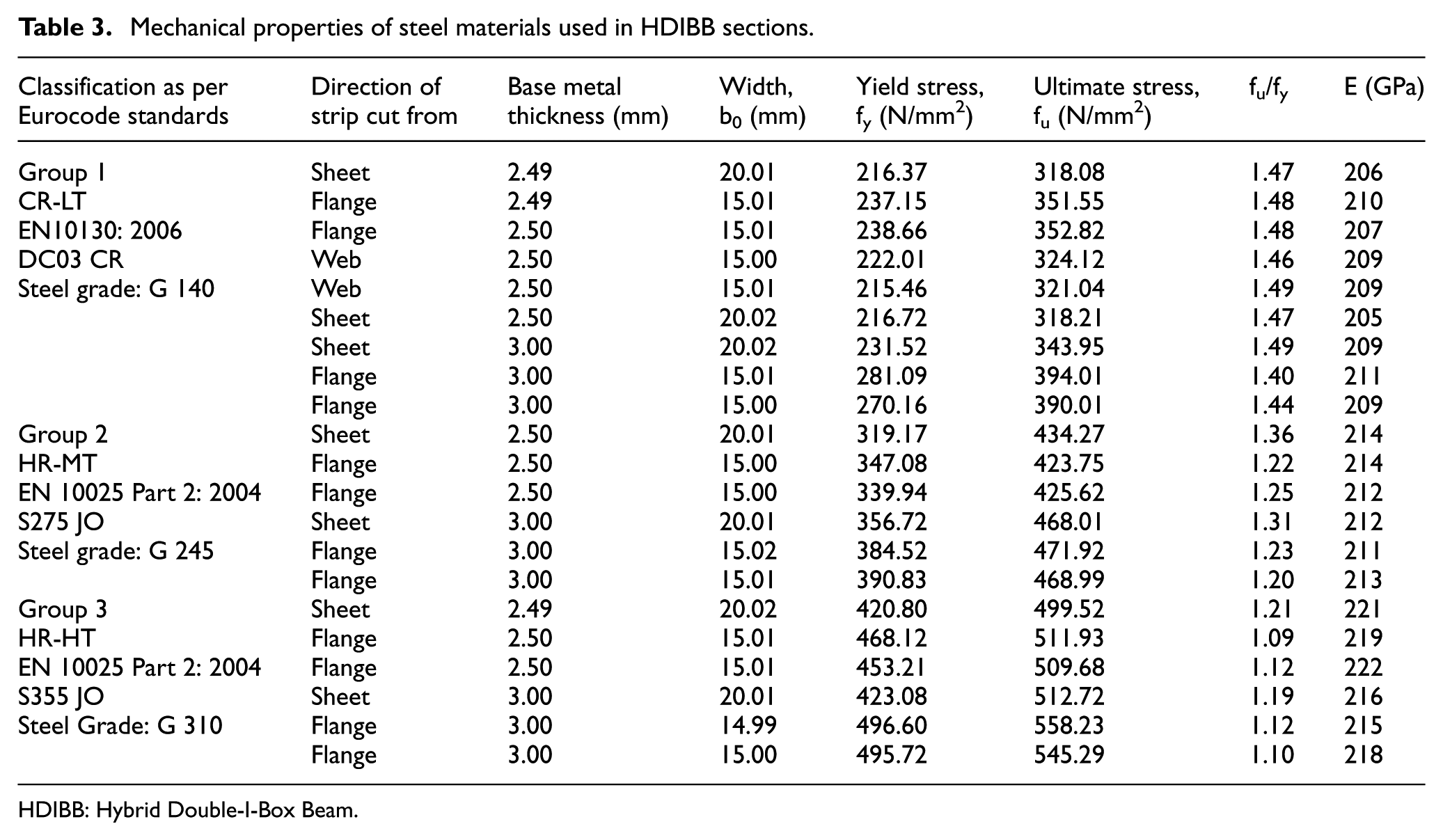
HDIBB: Hybrid Double-I-Box Beam.

Stress–strain curves for different grades of tensile coupons extracted from various parts of the sections.
The fu/fy ratio indicates the ductility in terms of elongation percentage over total gauge length which is 47%, 32% and 20% for low tensile, medium tensile and high tensile steel coupons, respectively. Cold-rolled low tensile steel coupons exhibited gradual stress–strain response. There was no well-defined yield point, hence 0.2% proof stress was taken as fy; large elongation and necking of specimens before failure was observed while testing, this shows high ductility behaviour in CRLT steel coupons. The hot-rolled medium and high tensile steel coupons exhibited sharp responses, hence their yield stresses were taken from the well-defined yield points.
The best-fit Young’s modulus (E) was obtained from the test. The differences in E values ranging from 207 to 222 GPa are because of the various grades of steel. Ranging from lower grade to higher grade, the E value improved, whereas the ductility reduced. The ratio of ultimate strength to yield strength of structural steel products as recommended by EN 3.1.1 clause 3.2.2 is >1.10. In the present investigation, all the materials satisfied the required norms.
Test set-up and procedure
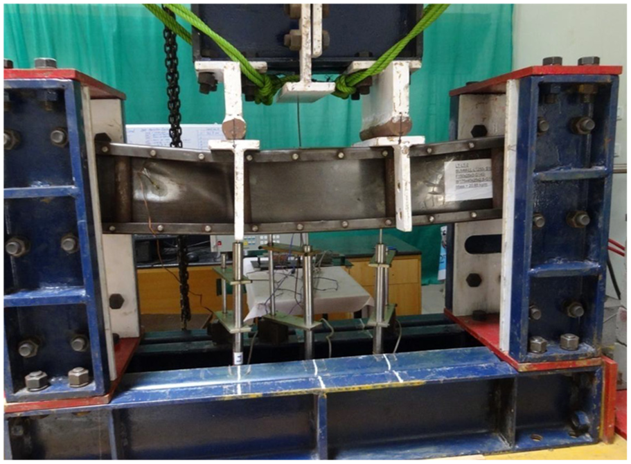
The section bending resistance of DIBBs and HDIBBs were determined based on four-point bending tests (i.e. two-point loading at one-third span with simply supported end conditions). Figures 4 and 5 show the schematic line diagram of the set-up and the actual test set-up in the laboratory. The simply supported condition was adopted such that, one end is pinned while the other end has a roller that facilitates translation movement when beam deflects during testing. The support conditions are illustrated in Figure 6(i). Loading arrangement was specially designed for this test programme. Two round bar stiffeners are provided at one-third span on either side of the beam under loading points to avoid the premature failure due to web crippling and to achieve the pure bending in the constant moment zone. Stiffener plates are provided to the webs at the ends of the specimens. These plates act as a reinforcement that avoids tearing of plates during transverse loading (Acharya et al., 2013).
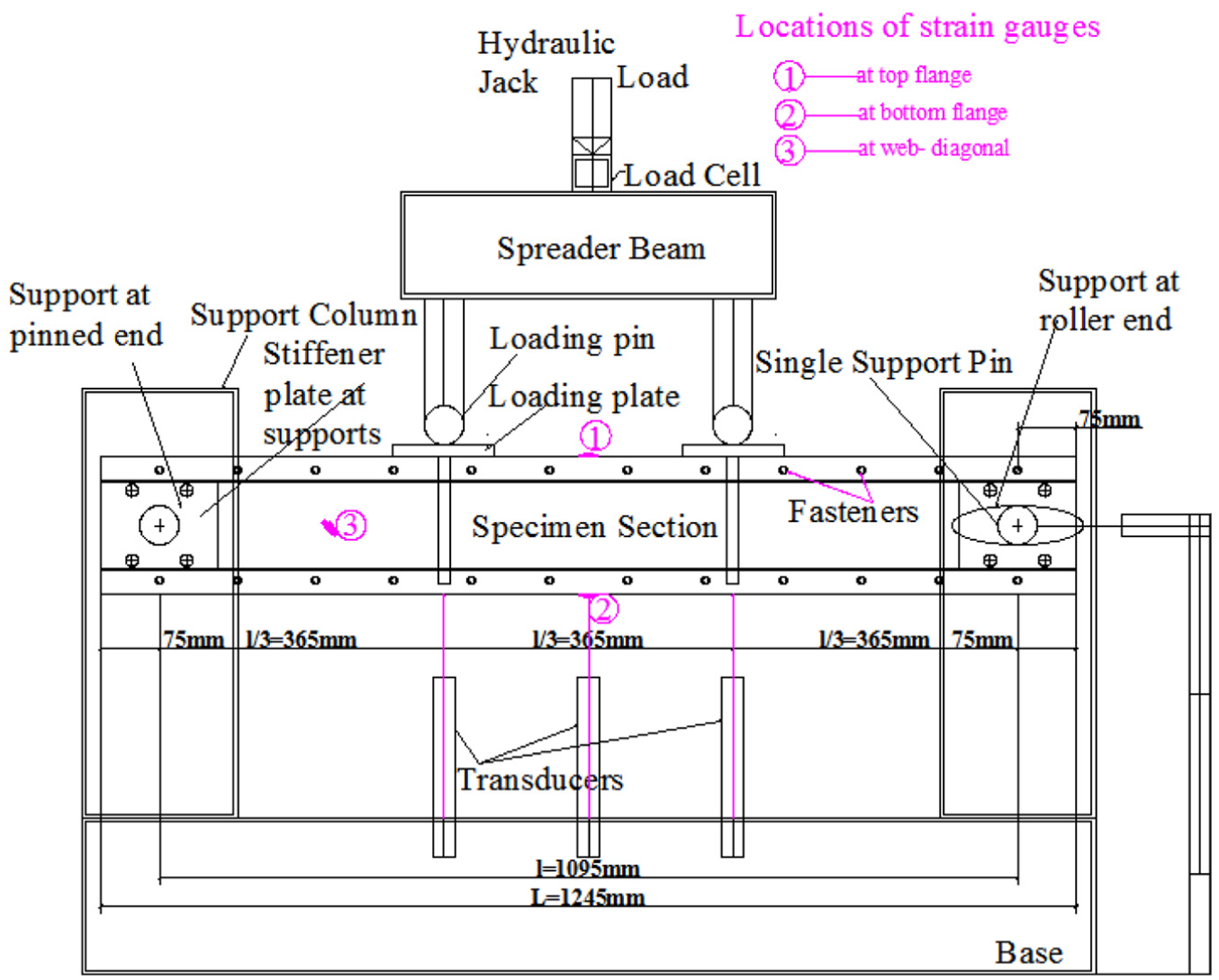
Line diagram of the test set-up.
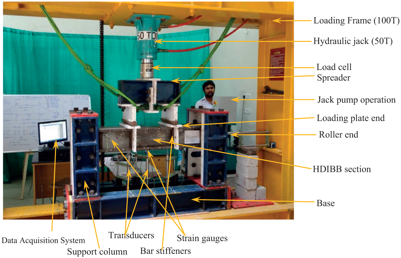
Actual test set-up in laboratory.
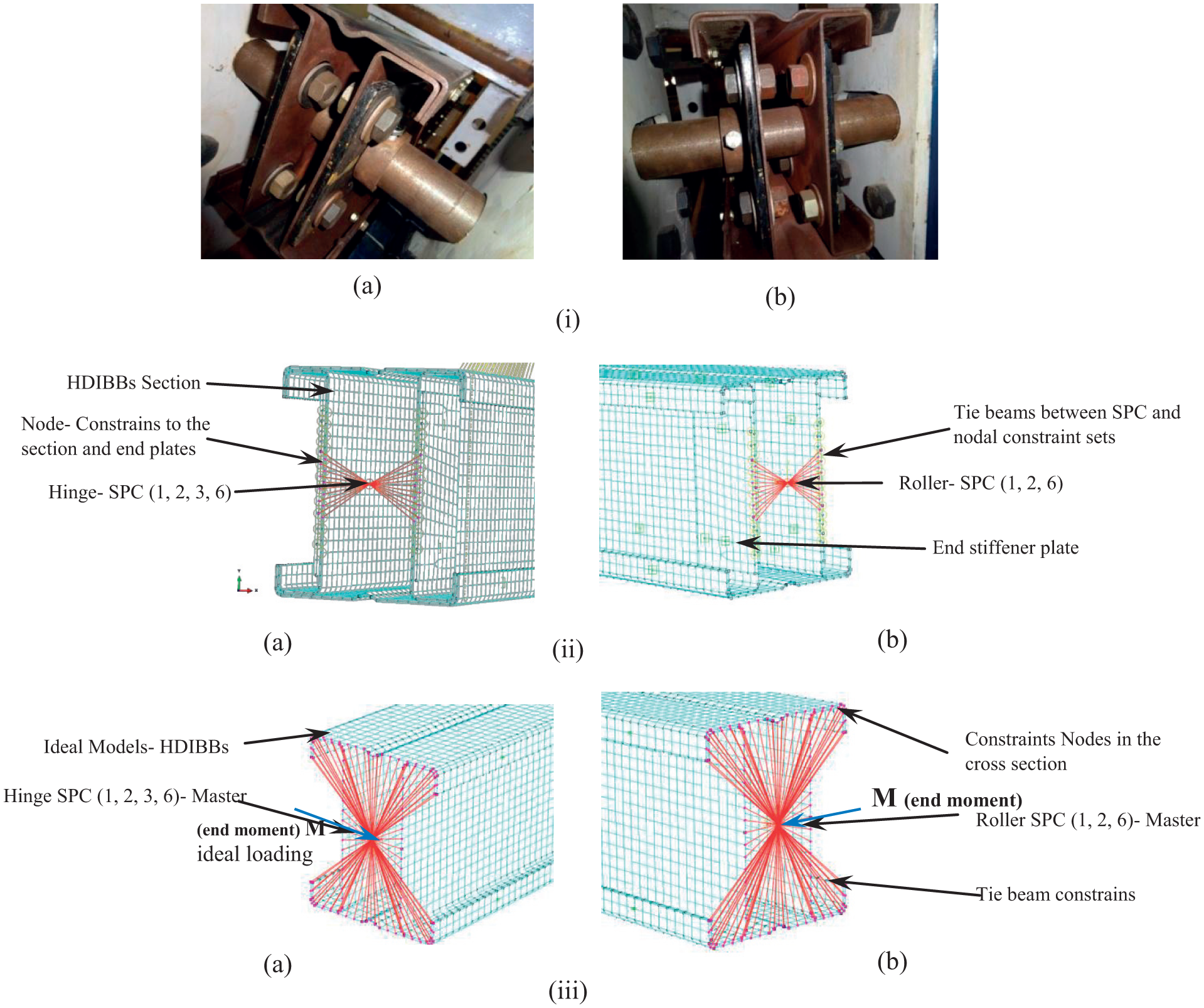
Support conditions: (i) actual support conditions – (a) hinge and (b) roller; (ii) experimental FE model boundary conditions – (a) hinge and (b) roller; (iii) ideal parametric FE model boundary conditions – (a) hinge and (b) roller.
The length of the beam for section moment capacity tests were chosen such that one-third portion from the support on either sides of the specimen is the shear zone and the middle one-third zone (365 mm) is the constant moment zone. End bearing of 75 mm was provided on either side of the support pins. The fasteners were evenly spaced at 100 mm c/c (S-100) located on the lips on the sections. Total length, L = 1245 mm, the effective span, l = 1095 mm and l/3 = 365 mm. Loading plates were used at the points of line loading on top of the flanges to avoid unexpected failure due to stress concentration over the flange plates (Kwon and Seo, 2012).
The four-point bending tests were conducted in a convenient 100-ton capacity loading frame. The 50-ton capacity hydraulic ram and pump used to apply the load and a load cell is attached to measure load. The vertical deflections under the specimens were measured using three linear variable displacement transducers (LVDTs): one LVDT was located at mid-span and two LVDTs are located at loading points, beneath the test specimen. The bending strains were measured using 5 mm electrical resistance strain gauges located on the top and bottom flanges of the specimen at mid-span and one diagonal shear gauge was affixed in the web of the shear zone to measure the shear stress in the shear zone section (see Figure 5). A 16-channel data acquisition system compiled with a computer was used to record the load, strain and deflection data for all the tests conducted.
Experimental test results and discussion
The applied moment is calculated by multiplying the measured applied load by the distance between the support and the loading point. In these built-up sections, the web elements are always non-compact (NC) sections and the flanges are either slender (S) or non-compact. The overall assembled HDIBB section was classified as non-compact or slender based on the flange slenderness. All specimens failed by local buckling of top compression zone at mid-span of the sections. Flange local buckling (FLB) and flange-web local buckling (FWLB) were the main types of buckling in-homogeneous sections, whereas web local buckling (WLB) and web-flange local buckling (WFLB) were observed in hybrid sections. In hybrid sections having B/D ratio less than 1, with hybrid parameter Φh = fyf/fyw ratio less than 2.0 primarily failed due to web buckling (WLB) or combined web-flange buckling (WFLB). Sections having B/D ratio greater than or equal to 1, due to more slenderness in flange portion, and Φh = fyf/fyw ratio greater than 2 primarily failed due to FLB or combined FWLB. The lean sections had more vertical deflection than stocky sections in all three series of tests. The types of local buckling failures in HDIBB sections are tabulated in Table 4. Figure 7 shows the various modes of local buckling failure of actually tested beam specimens.
Section moment capacities based on EN 1993-1-3 compared with experimental and finite element analysis results.
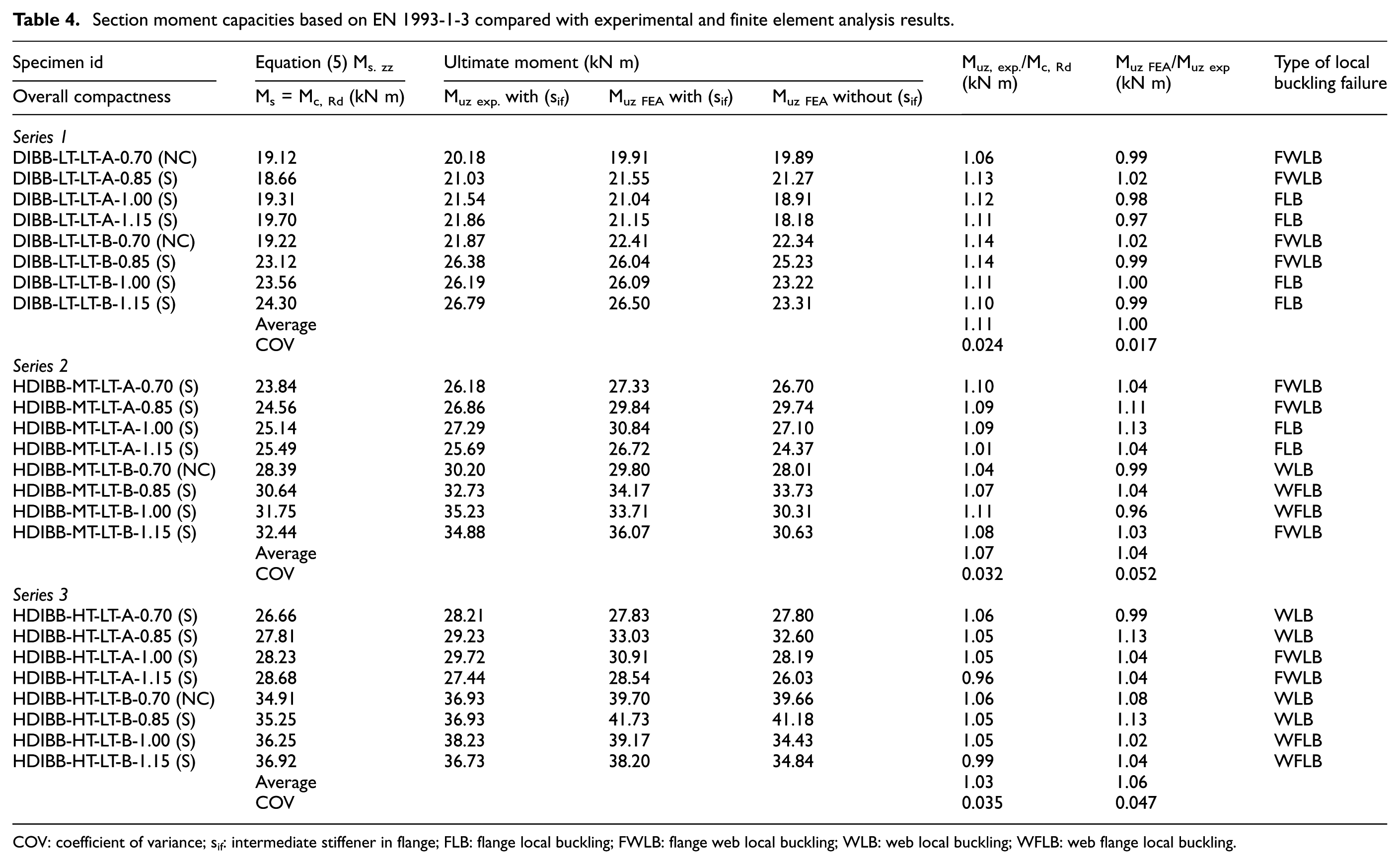
COV: coefficient of variance; sif: intermediate stiffener in flange; FLB: flange local buckling; FWLB: flange web local buckling; WLB: web local buckling; WFLB: web flange local buckling.
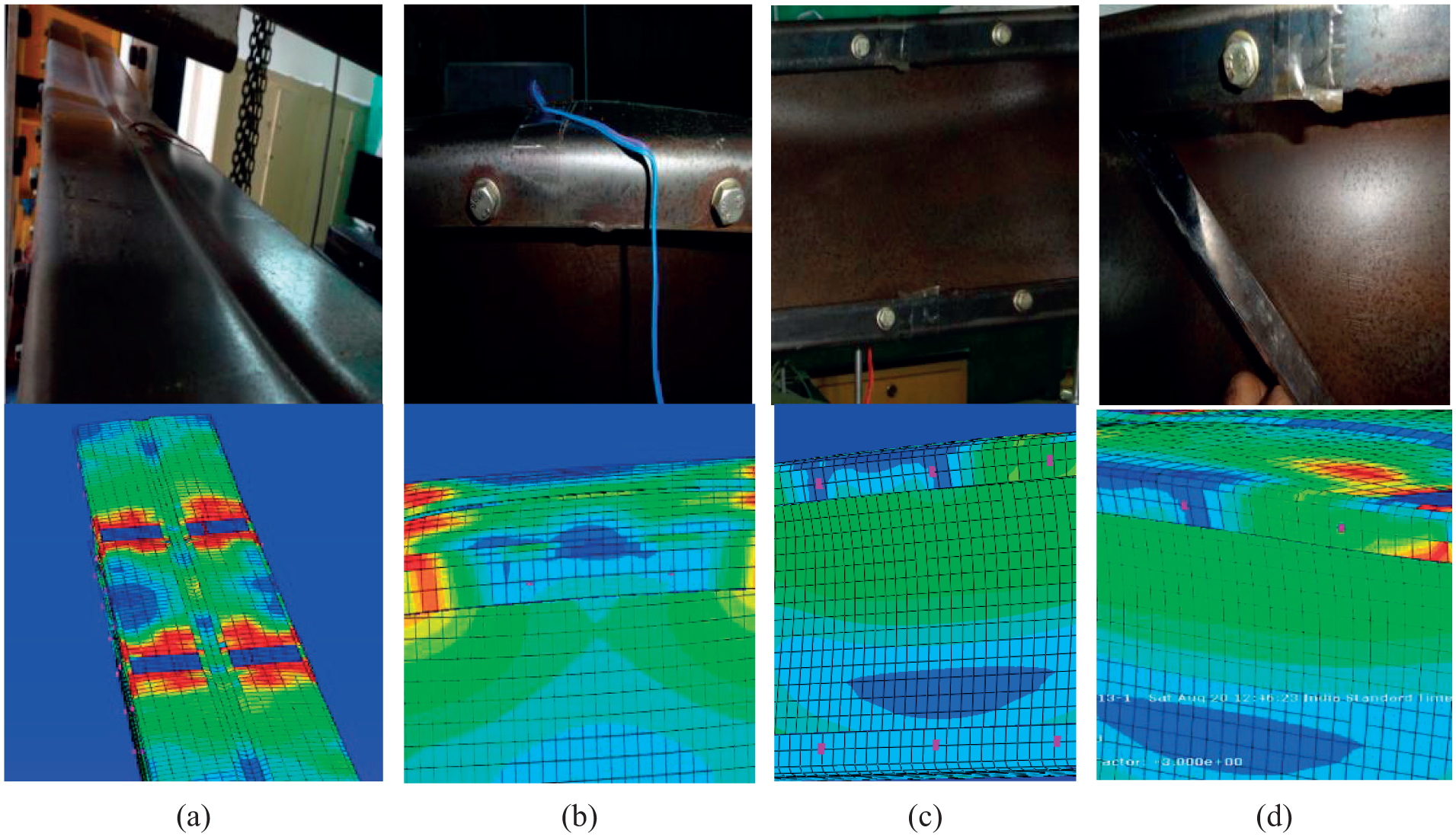
Failure types – tests and FEA: (a) flange-web buckling, (b) flange buckling, (c) web-flange buckling and (d) web buckling.
Typical moment versus vertical deflection plots for few HDIBB sections are illustrated in Figure 8. For homogeneous sections, the moment versus deflection curves included a large yield plateau, whereas in hybrid sections, there was less or no yield plateau. The longitudinal strains are as high as >2000 micro-strain in stocky HDIBBs to as low as <1000 micro-strain in lean DIBBs. The strain moment versus deflection graphs were plotted using longitudinal bending strains from top and bottom flanges. Strain calculated moment versus deflection plots show good agreement with applied load calculated moment versus deflection curves. Typical experimental moment versus longitudinal strain and web shear strain curves are presented in Figure 9.
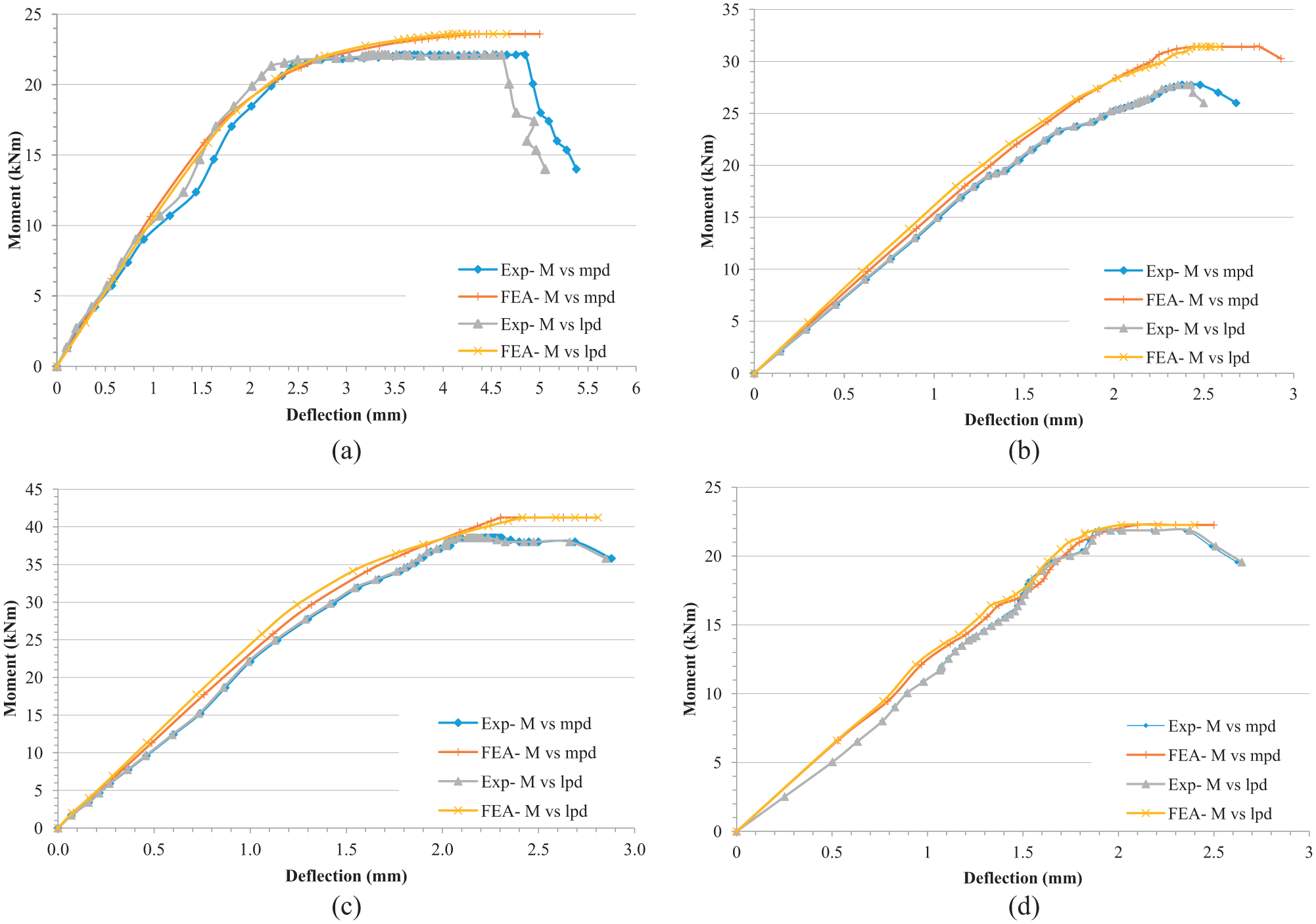
Moment versus deflection graphs of various HDIBB sections: (a) DIBB-LT-LT-B-0.70 NC, (b) HDIBB-MT-LT-A-0.85 S, (c) HDIBB-HT-LT-B-1.00 S and (d) DIBB-LT-LT-A-1.15 S.
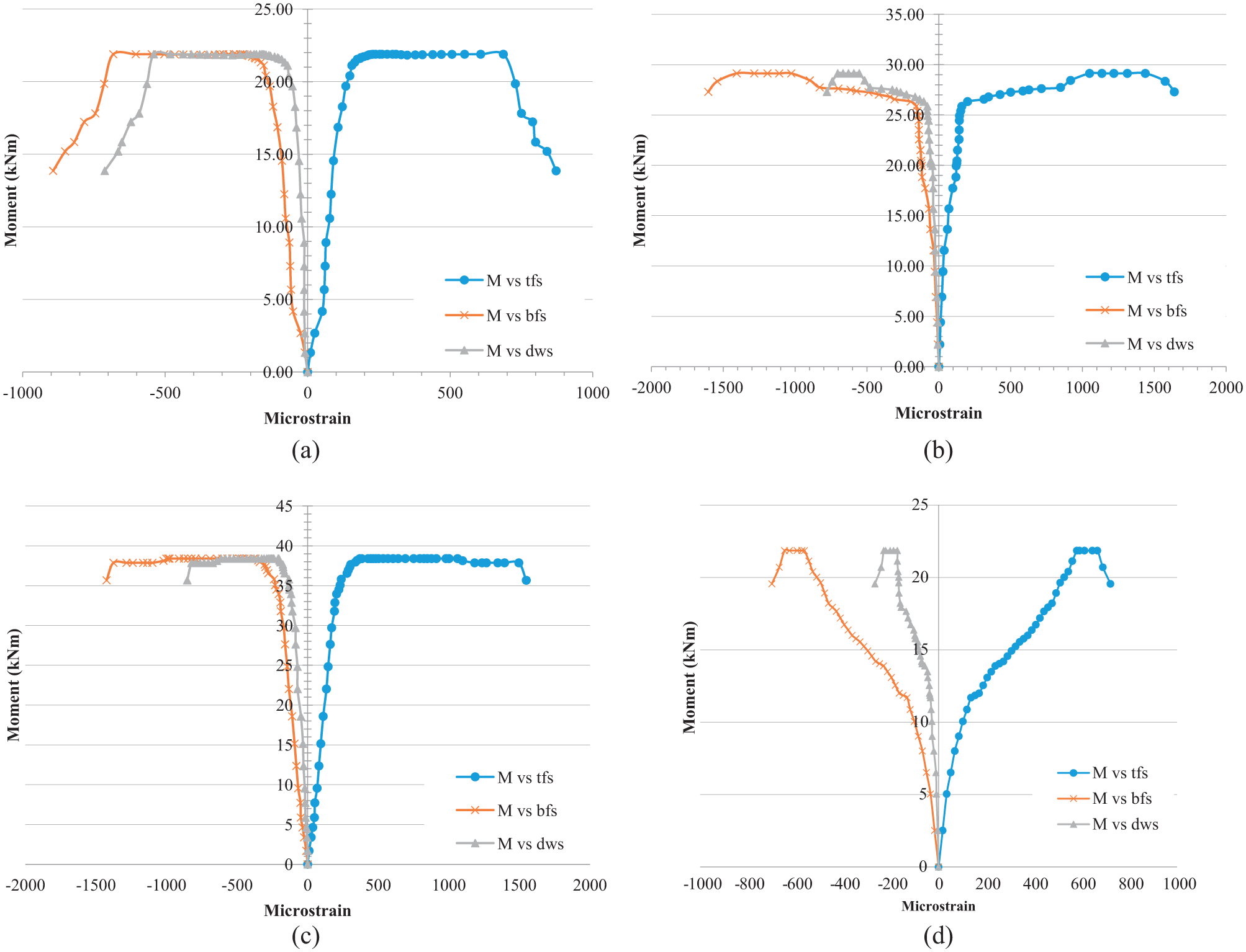
Moment versus strain graphs of various HDIBB sections: (a) DIBB-LT-LT-B-0.70 NC, (b) HDIBB-MT-LT-A-0.85 S, (c) HDIBB-HT-LT-B-1.00 S and (d) DIBB-LT-LT-A-1.15 S.
Additional observations were made in the test programme first, strain readings obtained from a diagonal strain in the web portion which was as high as >1000 micro-strain with a definite yield plateau in slender lean sections to as low as <400 micro-strain in wide stocky sections. Second, using LVDT, the maximum translational movement at roller support end was observed for all sections. Lean sections (B/D < 1.00) had more translational movement when compared with stocky sections (B/D ≥ 1.00) in all the series of tests.
Moment versus deflection plots show that the initial response of all DIBB and HDIBB sections was linear until first yield point was reached and after that, the non-linear behaviour was exhibited. From the bar charts shown in Figure 10, the moment capacity of lean A-0.70 (i.e. B/D = 0.70 and tf = 2.5 mm) homogeneous sections is as low as 20.18 kN m when compared with 28.21 kN m as that in hybrid sections of same weight. Similarly, moment capacity of wide (i.e. B/D = 1.2 and tf = 3.0 mm) homogeneous sections is as low as 26.79 kN m when compared to 36.73 kN m as that in high strength hybrid sections of same weight. Based on the test results, it was determined that with the increase in hybrid parameter ratio, Φh from 1 to 1.75 and 2.21, respectively, there is increase in section moment carrying capacity. The increase in the section capacity is such that first, 20%–30% increase in strength for B/D < 1.0; and second, 10%–15% increase for B/D > 1.0, correspondingly. The experimental section bending resistance for all the tests is tabulated in Table 4.

Bar charts showing experiment moment capacities of tested beams: (a) HDIBBs of flange thickness, tf = 2.5 mm and (b) HDIBBs of flange thickness, tf = 3.0 mm.
FEA
The FE programme ABAQUS is simulation software tool for modelling thin-walled structural elements incorporating both material and geometric imperfections. These computations were done in Advanced CAD Laboratory at Government College of Technology, Coimbatore, India.
Choice of element type
The primary aim of the investigation is to predict the moment capacity of short-span HDIBBs that exhibit local buckling under traverse loading. All the sections, the flanges, webs and end plates are modelled by thin shell S4R5 element in ABAQUS modelling element library. Multi-point constraints (MPCs) were used for modelling bolted connection fasteners; the C3D4R elements have been used to model end bearing stiffeners and the bar stiffeners.
Material properties, geometric imperfections and residual stresses
The material properties of various grades of steel obtained from the standard coupon tests were given as input to the experimental FE models. ABAQUS uses true stress and strain data, and hence the values of engineering stress and strain obtained from coupons tests were converted and used. The local geometric imperfection of the beam was taken as depth/150. The global geometric imperfection of the beam was taken as 1/1000th of the length of the beam. There was no temperature-induced stresses during manufacturing and fabricating, so the membrane residual stresses are neglected in this analysis. The flexural residual stresses are usually re-introduced in coupon tests and therefore have already been included using stress–strain curves from material tests (Niu et al., 2014). The effect of cold-forming at corners was also very less since press-brake cold-forming method was adopted. Among the previously referred literature, it is a general practice to ignore the residual stresses and the increased yield stress at the corners in the FEA for CFS members while analysing the experimental FE models (Wang and Young, 2015).
However, for ideal FE parametric models, the residual stress distributions were considered as proposed in Schafer and Pekoz (1998) model for press-brake formed channels as shown in Figure 11(a). The proposed residual stress models adopted in the present research for ideal model FEA is as shown in Figure 11(b). For the connector sections, the strength of bolts as specified by the manufacturer was given as input in ABAQUS fastener properties. In-depth research on the fastener characteristics is beyond the scope of this research.
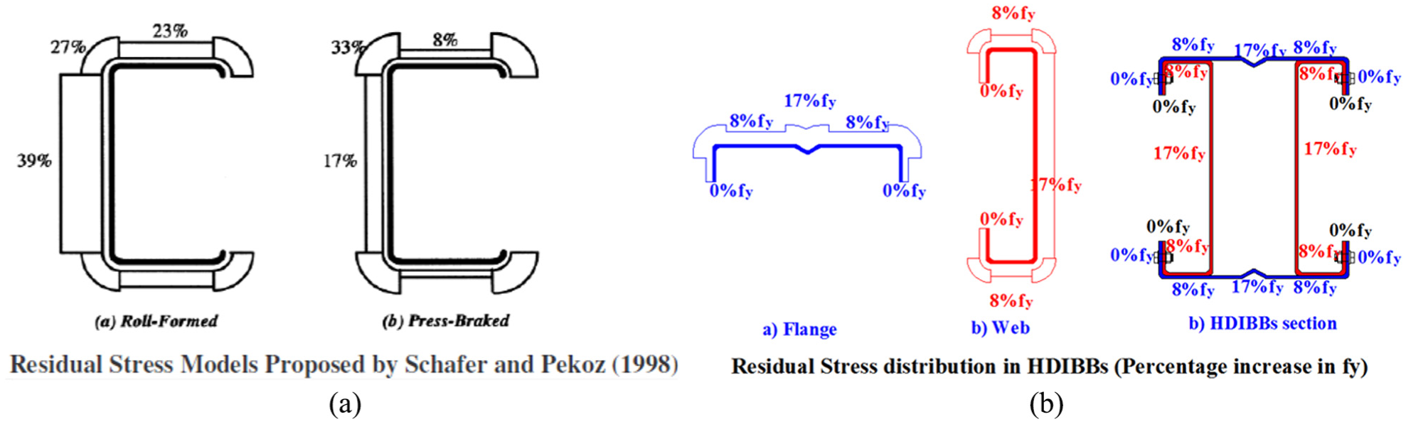
Residual stress models adopted in this research: (a) Referred Model and (b) Proposed Model.
FE mesh
General hard surface contact was adopted to avoid contact problems in-between the layers, master-slave surfaces were created between the surfaces various instances in the assembly. Frictionless and hard contact was adopted. One major problem while meshing sections with contact faces is that there are penetrations of layers during analysis. From various trials, it was found that square mesh of size 10 mm × 10 mm can be adopted for modelling all parts of the assembled HDIBB sections to avoid any penetrations.
Boundary and loading conditions
Simply supported boundary conditions and load application were simulated to the maximum precision to reproduce the procedure adopted in experimental testing. In ABAQUS, the length of the beam was along z axis and the x-y axis plots the cross section. 1, 2 and 3 represent translations, whereas 4, 5 and 6 represent the rotations along x, y and z directions, respectively. At pinned end support, 1, 2, 3 and 6 were restrained, whereas in roller end support, 1, 2 and 6 were restrained with single-point constraints (SPCs) with rigid body tie node constraints to the specimen and the end plates. The support conditions adopted in experimental model FEA are as shown in Figure 6(ii). The two-point loads were distributed over a loading plate size area in FE model using MPC control points and tie nodes. Full model was always simulated so that the observations made in numerical methods can be compared with the original tests.
Analysis
In the FEA, two types of analyses were performed. First, linear perturbation bifurcation buckling analysis was performed to obtain the critical Eigen buckling modes, wherein the majority of the cases is either of the first two Eigen modes. The shape is incorporated in the second step of analysis along with the magnitudes of the imperfections. Second, the non-linear static analysis was performed using static Riks method with a load proportionality factor of 1.0 including the effects of large deformation and material yielding. The variable arc-length Riks method was adopted to solve instability problems associated with non-linear buckling of HDIBB sections.
Comparison between experimental test results and numerical results
Two types of FE models one with intermediate flange stiffener and another without intermediate flange stiffener were modelled and analysed to study the effect of intermediate stiffener. The results are tabulated in Table 4. Based on numerical results obtained, for lean sections, the flange stiffener had little effect on section bending resistance, whereas in slender wide flange bulky sections, the intermediate flange stiffener had significant effect on cross-section moment capacity. About 8%–10% increase in the section capacity. From Table 4, the mean ratio of experimental moment capacities and FEA moment capacities were 1.00, 1.04 and 1.06 with coefficient of variance (COV) 0.017, 0.052 and 0.047 for Φh varying as 1, 1.75 and 2.21, respectively. The difference in the ratio of Mexp.z/MFEA is very negligible. Figure 8 shows the typical comparison graphs of moment versus deflection of various DIBB and HDIBB sections obtained from experimental tests and non-linear (FEA) of experiment FE models. All the curves in Figure 8 closely fit with the experimental curves. Moreover, the Von-Mises stress behaviour shown in results odb., display in ABAQUS view port, resembles the exact buckling failure of the experimentally tested section. Typical buckling failures of non-linear FEA compared with the failures exhibited in real tested beams are shown in Figures 7 and 12. There is good agreement between experimental and numerical results, hence the FE model is verified and validated. The validated FE method was further extended to perform parametric studies.

Local buckling of an experimental finite element model (FWLB).
Parametric studies
The FE method developed to simulate and analyse the experimental models shows that the results are reliable. Parametric study has been performed in four series for ideal FE models fabricated using various steel grade materials recommended in EN 1993-1-3. Ideal thin-walled HDIBB sections have idealized dimensions ideal for support conditions and end moments are applied as loads for analysis (Wanniarachchi, 2005). The ideal support conditions are shown in Figure 6(iii) and the load cases are illustrated in Figure 13. Classical elastic-perfect plastic material model is used for all specimens. The length of beam sections adopted was 1000 mm for all the ideal models. The geometrical imperfections, fasteners detailing, mesh size and the analysis procedure adopted are similarly explained in experimental FE modelling. The proposed residual stress models adopted in this research for ideal model FEA is shown in Figure 11(b).
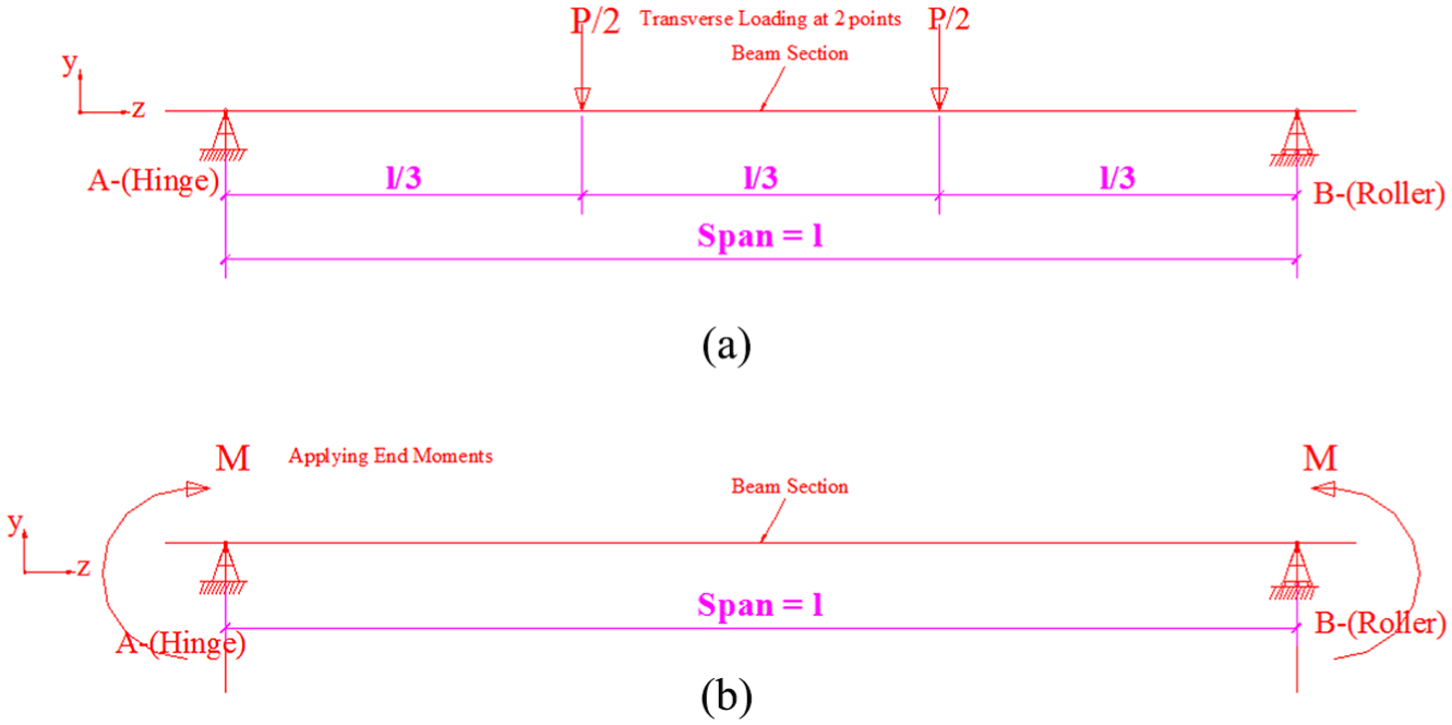
Loading cases for experimental and ideal finite element models: (a) experimental FE model – section moment capacity test and (b) parametric ideal FE model – section moment capacity test.
The basic yield strengths for different grades of steel materials used in parametric studies were (1) low tensile (LT) – 275 MPa; (2) medium tensile (MT) – 355 MPa; (3) average tensile (AT) – 420 MPa; and (4) high tensile (HT) – 460 MPa. For all the ideal beams, the webs (lipped channels) were made of low tensile steel plates. The flanges were made up of different high strength plates for different ideal hybrid models. Factors considered were as follows: first, the hybrid parameter ratio Φh = fyf/fyw that varies as 1.0, 1.3, 1.5 and 1.7. Second, the ratio of B/D that varies as 4/6, 5/6, 6/6 and 7/6. And third, flange thicknesses (tf) as 2.5 and 3.0 mm, accordingly. The results were compared with the predictions from EN 3-1-3 design standards for section bending resistance as shown in Table 5. Typical loading cases for experimental and ideal FE models are shown in Figure 13. FLB failure of an ideal model is illustrated in Figure 14.
Parametric studies of ideal model HDIBBs result.
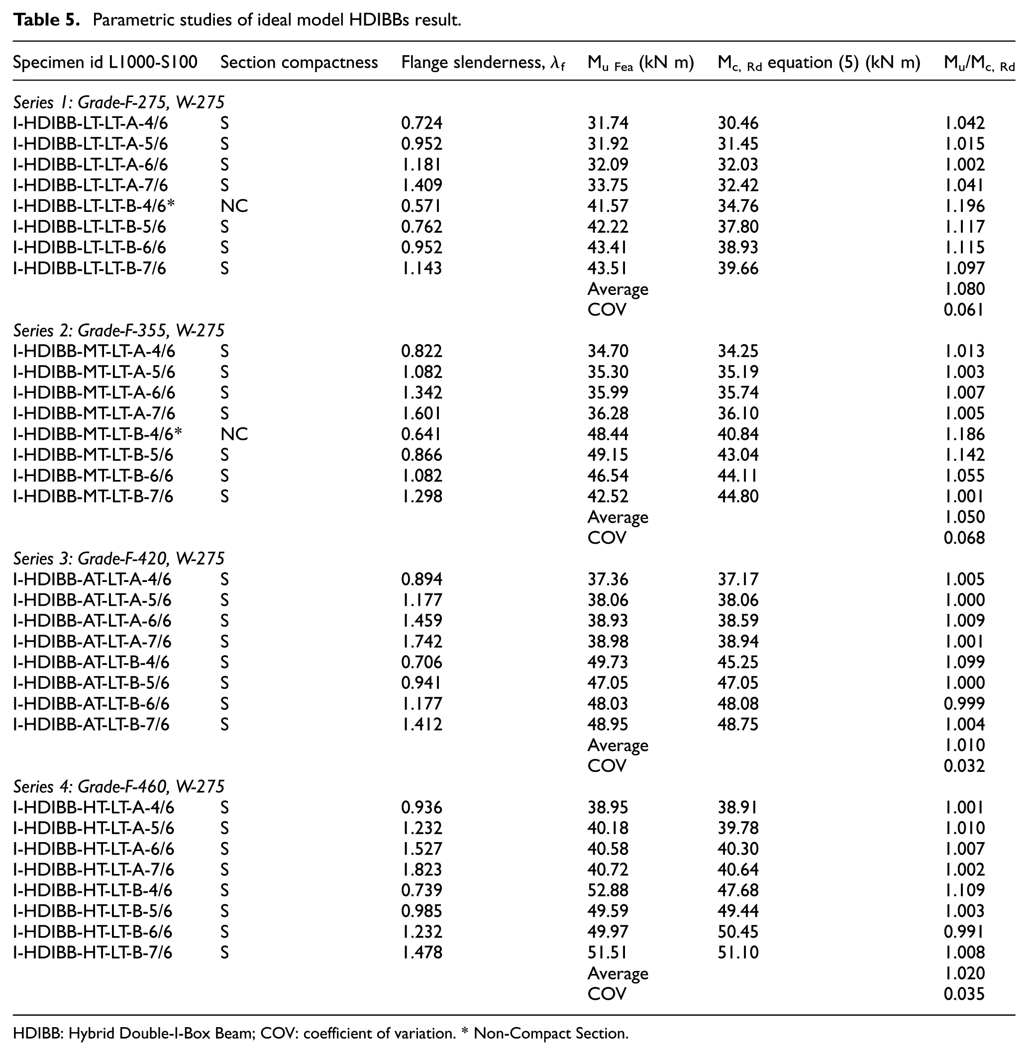
HDIBB: Hybrid Double-I-Box Beam; COV: coefficient of variation. * Non-Compact Section.
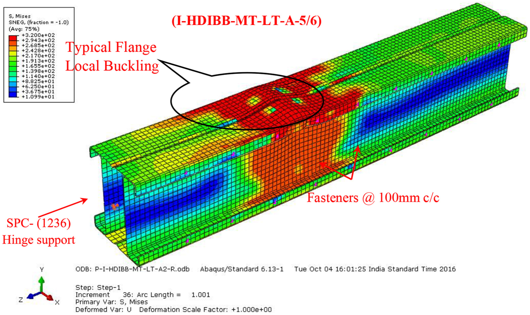
Flange local buckling failure of an ideal finite element model.
Comparison of experimental and FEA ultimate moments with current specifications
Design rules based on CFS structures standards EN 3-1-3
The section bending resistance (Ms) is based on initiation of yielding in the extreme compression fibre of the cross section according to EN 3-1-3. The effective widths (beff) of plate elements are accounted for calculation of effective section modulus (Weff) according to (equation (2)). The slenderness of the plate elements has a direct influence on reductions in the strength of the section subjected to local buckling. If the section is compact or non-compact section, then gross section modulus (Wel) and the section moment of resistance are calculated according to equation (3).
The design section moment capacity Mc,Rd is calculated based on Cl. 6.1.4.1 of EN 3-1-3

If

If

For double supported plate elements,
For out-stand elements,
For stiffened elements,
The effective breath of plate element (beff.) depends on the slenderness,
According to Eurocode 1993-1-5:2006. Cl. 4.4
For internal elements
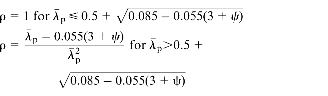
For out-stand elements

According to Eurocode 1993-1-3,
From tables 4.1 and 4.2 of EN 1993-1-5 (2006),
The transition from the cross section class 3 to class 4 is of special importance showing b/t limits with
Design calculations and proposed modifications
HDIBB sections have different grades of materials, so the calculation of effective design section moment capacity can be split up into two parts given in equation (4)

where
The calculations were made with centre line dimensions with sharp edges. The influence of rounded corners is not considered as per Cl.5.1 of EN 1993-1-3 since the internal radius,
Moment capacities of HDIBB sections based on Eurocode 1993-1-3: 2006.
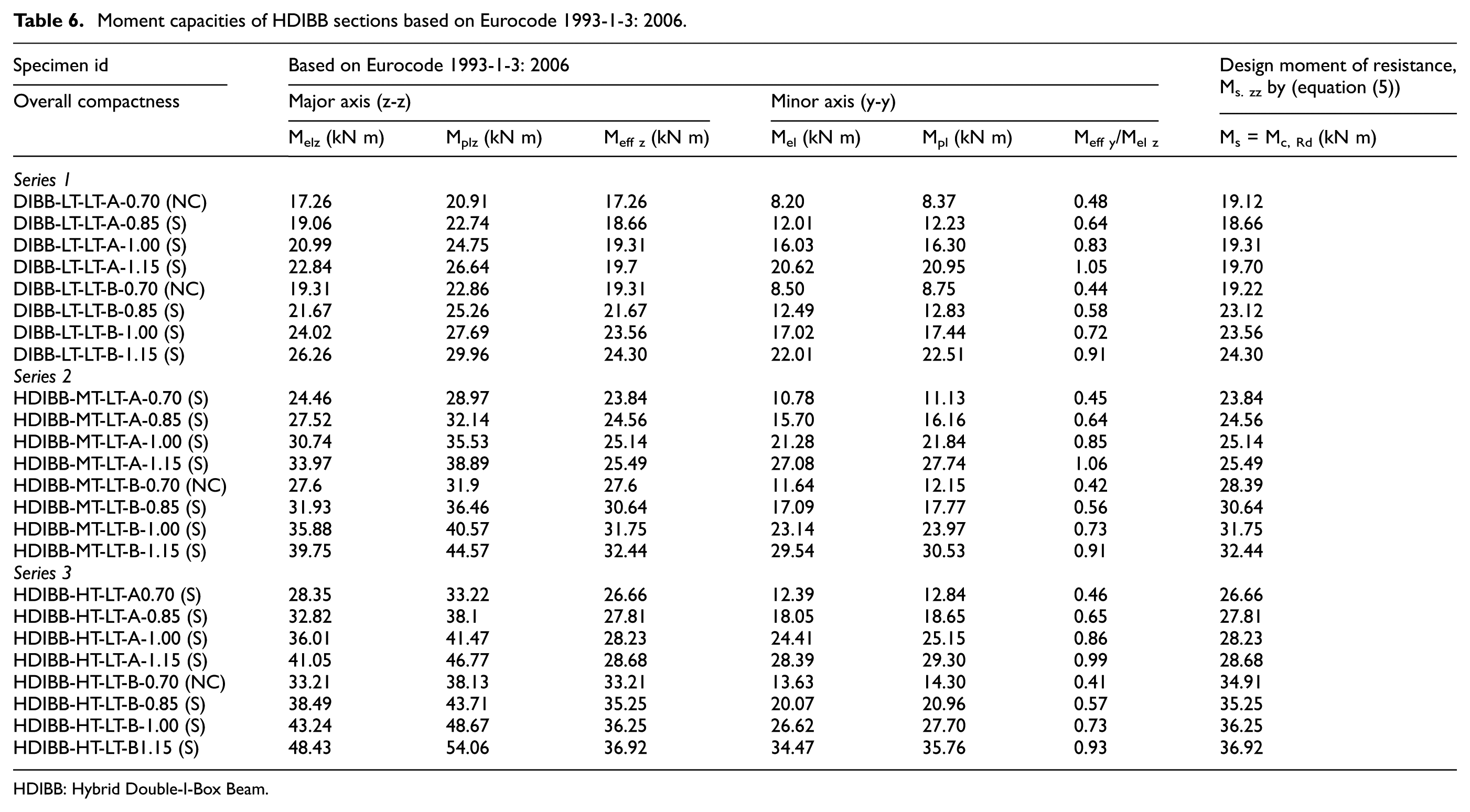
HDIBB: Hybrid Double-I-Box Beam.
Results and discussion
A total of 24 bending tests that include 8 homogeneous sections and 16 hybrid sections were carried out in the experimental study. All specimens failed by local buckling of top compression zone at mid-span of the sections (see Figure 15). Typical moment versus vertical deflections and longitudinal strain graphs from few of these tests were illustrated. Four interactions of local buckling failure modes were identified, namely: (1) FLB, (2) FWLB, (3) WLB and (4) WFLB. The hybrid parameter was greater than 2 and there was an increase in strength, but from the real coupons test results, it was evident that in the present investigation, the hybrid parameter was approximately equalled to 2. Built-up Double-I-Box closed-form sections have two axes of symmetry; therefore, there will be no change in neutral axis when the cross section is subjected to pure bending and this leads to an important simplification for thin-walled sections because additional bending moments created due to this shift of neutral axis does not take place in a closed-box section when compared to the open sections. Thus, the lateral-torsion buckling can be disregarded for box sections. There was no lateral movement or lateral deflection observed in any of the bending tests in both experimental and numerical studies (Figure 16).
Local buckling failure of actual beam LT-LT-A2 (FWLB).
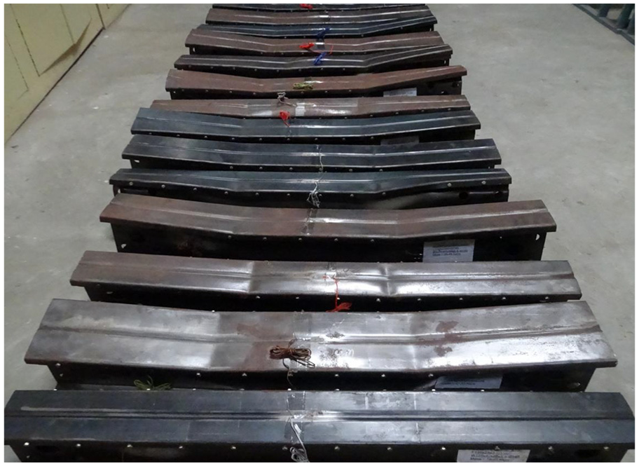
Experimentally tested HDIBB sections.
The primary aim of this study is to find the moment capacity of new Hybrid Double-I Box Beam sections and verify the feasibility with predicted moment capacity from the current CFS EN 1993-1-3 (2006). The experimental ultimate moment and non-linear FEA moment achieved by each test specimen is tabulated and compared with design moment of resistance capacity predictions by the code. First, for low strength homogeneous sections, the predicted results are slightly conservative. The code allows only the basic yield strength of the material to be used and does not allow the inelastic bending capacity. Hence, the ratio of ultimate to the predicted moment from code has mean value as high as 1.11 and COV as 0.024. Second, for medium strength and high strength hybrid sections, the predicted moment results are almost equal to the experimental results. There was less deviation in the ratio of ultimate to the predicted moment and has mean values of 1.07 and 1.04 with COV as 0.032 and 0.022, respectively.
Conclusion
An experimental and numerical investigation on section bending resistance capacity of built-up thin-walled homogeneous and Hybrid Double-I-Box Beam (DIBB and HDIBB) sections was performed and presented. Four different failure patterns of local buckling phenomenon occurred in the CFS built-up sections were captured in this study. Based on this study, the following conclusions were arrived:
The shape of the HDIBB sections is beneficial such that they have more material in the flanges far away from the horizontal-centroidal axis, so section modulus is increased, eventually, the bending strength is increased in major axis (z-z). The larger the size of the hollow box-web section, the flexural strength and torsion rigidity are increased in minor axis (y-y).
The hybrid sections consist of higher yield strength materials in their flanges that offer higher resistance to local flange buckling in the compression zone, eventually the section bending resistance is enhanced when compared to homogeneous sections, therefore technically gains more strength to weight.
The cross-sectional local buckling resistance of a HDIBB section is the arithmetical summation of moment capacity of individual parts assembled into a whole built-up section.
The provision of an intermediate flange stiffener had a significant effect in increasing the load-carrying capacity of wide flange built-up sections. The flange stiffener reduces the plate slenderness and increases the effective section for load distribution.
There exists good agreement between experimental and numerical results in terms of section moment capacities and respective failure modes. This demonstrates that the FE method adopted in this study is reliable.
The design section moment of resistance (Ms) of DIBBs and HDIBBs sections which are subjected only to local buckling failure, then the following equation is feasible and recommended, provided that the materials satisfy the Eurocode EN 1993-1-3 (2006) norms,
Footnotes
Acknowledgements
The authors also gratefully acknowledge Easwari Engineering College, Chennai, and Centre of Excellence of PSG College of Technology, Coimbatore, for providing the laboratory facilities.
Declaration of Conflicting Interests
The author(s) declared no potential conflicts of interest with respect to the research, authorship and/or publication of this article.
Funding
The author(s) disclosed receipt of the following financial support for the research, authorship and/or publication of this article: The authors would like to thank Government College of Technology, Coimbatore, for providing TEQIP-II funding to the first author (Reg. No. 1314169121) as a monthly stipend for first 2 years of the full-time PhD research programme. The authors would especially thank all the financial support from other sources.