



Abstract
Concrete-filled steel tubular structural members can be recognized as an effective mean to improve the mechanical behavior in terms of strength, stiffness, ductility, and energy dissipation for the initial recycle aggregate concrete deficiencies compared with natural aggregate concrete. A small-scale model of square concrete-filled steel tubular column–reinforced concrete beam frame realized employing 100% recycled coarse aggregates was tested under combined axial loads and cyclic reversed lateral flexure. The failure modes, plastic hinges sequence, hysteresis loop, skeleton curve, stiffness degeneration, energy dissipation capacity, and ductility of the frame were presented and analyzed in detail. The structural behavior of square concrete-filled steel tubular column–reinforced concrete beam frame with 100% recycled coarse aggregates was compared with circular concrete-filled steel tubular column–reinforced concrete beam frame made with 100% recycled coarse aggregates. A fiber-based program model for the nonlinear analysis of concrete-filled steel tubular column–reinforced concrete beam frames incorporating recycled coarse aggregates was developed using SeismoStruct, to highlight the effect of recycled coarse aggregate content on mechanical behavior of recycled aggregate concrete and the confinement effect provided by outer tubes on core concrete. The analysis results show that the numerical model can well simulate and predict the seismic behavior of concrete-filled steel tubular column–reinforced concrete beam frames with 100% recycled coarse aggregate content. Both experimental and numerical results demonstrate that concrete-filled steel tubular column–reinforced concrete beam frames with large content of recycled coarse aggregates have a receivable seismic performance, and it is feasible to apply and popularize recycled aggregate concrete into concrete-filled steel tubular structures in seismic regions.
Keywords
Introduction
Recycled aggregate concrete (RAC) has been recognized as a cleaner production in construction activities from the viewpoint of recycling and reuse of waste concrete (Tam et al., 2016). A lot of experimental investigations have demonstrated that it is feasible and sufficient to use RAC as a structural concrete in Civil Engineering, even though the initial deficiencies (e.g. micro cracks and adhered cement mortar) of RAC can reduce its mechanical behavior (e.g. lower strength, elastic modulus, energy dissipation, durability but larger peak strain, Poisson’s ratio, shrinkage and creep), compared with natural aggregate concrete (NAC, also known as normal concrete) (Ceia et al., 2016; Kou and Poon, 2012; Li, 2008; Liu et al., 2011; Lye et al., 2016; Matias et al., 2013; Rui et al., 2016; Thomas et al., 2013; Vieira et al., 2016; Zega and Maio, 2011).
With regard to popularizing RAC materials, many efforts were made to enhance the mechanical behavior of RAC structures. Actually, confined concrete structural members can be an effective solution to strengthen the imperfection of RAC. Based on this philosophy, Konno et al. (1997), Xiao et al. (2012), Chen et al. (2014b), Yang and Han (2006), Yang and Ma (2013), Shi et al. (2010), Wang et al. (2015), and Zhao et al. (2016) accomplished a mass of experimental researches to investigate the influence of recycled coarse aggregate (RCA) content on the compressive behavior of recycled aggregate concrete-filled steel tubular (RACFST) columns. From these tests, Chen et al. (2016) summarized the compressive strengths and proposed a strength prediction model of RACFST by considering the influence of RCA content. Moreover, a basic conclusion can be made from Chen et al. (2016): (1) for the pre-wetted RCAs, the compressive strength of RACFST can be reduced when increasing the RCA content; (2) for the non pre-wetted RCAs, the compressive strength of RACFST increases with an increase of RCA content.
In order to reveal the seismic failure mechanism of RACFST, Yang et al. (2009) first conducted the experimental work on the performance of RAC-filled square steel tubular columns by cyclic loading beam-tests. It should be pointed out that the RCAs used in Yang et al. (2009) were pre-wetted before fabricating the specimens. With respect to the no pre-wetted RCAs, Zhang et al. (2014) and Chen et al. (2017a, 2017b) tested 16 cantilever RACFST columns subjected to a constant load and cyclic bending loads. The cyclic load carrying capacities of RACFST affected by RCA content and pre-wetting are similar to the before-mentioned static compressive strengths of RACFST. In addition, Wu et al. (2012, 2013) performed cyclic tests on thin-walled steel tubular columns made from demolished concrete blocks or lumps with fresh concrete to investigate the effects of replacement percentages of the demolished concrete blocks and the thickness of steel tubes on their seismic behavior.
In spite of the extensive studies of RACFST members in the literature, the topics on the seismic behavior of concrete-filled steel tubular (CFST) column–RC beam frames realized employing 100% RCAs still have not been fully addressed, and only the test on circular CFST column–RC beam frame made with 100% RCAs was discussed by Chen et al. (2014c). Hence, the structural performance of another type of CFST column–RC beam frames using 100% RCAs, referring to square CFST column–RC beam frame with 100% RCA content, is not available in the literature and current design codes.
This paper firstly presents a test of a small scale model of square CFST column-RC beam frame realized using 100% RCAs in order to investigate its seismic behavior. The load–displacement curves, failure behavior, stiffness degeneration, energy dissipation capacity, and ductility of the test specimen were discussed in detail. Furthermore, the general behavior of square CFST column–RC beam frame with 100% RCAs was compared with circular CFST column–RC beam frame made with 100% RCAs reported in the existing literature. Finally, a computer program for the nonlinear analysis of CFST column–RC beam frames with 100% RCAs was developed to verify the rationality of this numerical model.
Experimental programme
Design of specimens
Materials
Ordinary Portland cement with a 28-day nominal compressive strength class of 42.5 MPa was used in this study. The fine aggregate used was river sands. The applied coarse aggregates were RCAs obtained from the waste concrete specimens in the Key Laboratory of Disaster Prevention and Structural Safety of China Ministry of Education. The physical properties of RACs are given in Table 1. According to Chinese Standard GB 50010-2010 (2010), steel bars of HPB235 (plain bar with diameter of 6 mm) and HRB335 (crescent ribbed bar with diameter of 14 mm) were adopted as the stirrups and longitudinal reinforcement in the beam, respectively; as for the square steel tube, the side length of outer tube and the wall thickness of steel plate were 150.9 and 5.0 mm, respectively. Table 2 shows the mechanical properties (yield strength fy, ultimate strength fu, elastic modulus Es, and yield strain εy) of the steel tube and reinforcement materials obtained from the material property tests.
Physical properties of NCA and RCA.

Mechanical properties of steels.

Mix proportions of RAC
100% RCAs replacing natural coarse aggregates (NCAs) were used with the aim to fully recycle and reuse the waste concrete. The target concrete strength for 28-day curing was set as around 50 MPa. Two steps were adopted to manufacture the beam-to-column frame: the first step is to infill the concrete into steel tubes and the second step is to place the concrete for the frame beam and basement beam. Hence, preparing the RAC in the frame was divided into two batches due to the sequence of fabricating the members of columns and beam. The mix proportions of the concrete as described in Table 3 were determined according to a foregoing investigation as reported by Chen et al. (2014c). It should be noted that the RCAs used in this test were not pre-wetted before casting the concrete.
Mix proportions of concrete (kg/m3).

NCA: natural coarse aggregate; RCA: recycled coarse aggregate.
r is the RCA content; W/C is the water-to-cement ratio; C is the cement; S is river sand.
Specimens details
In this test, one small-scale frame specimen was made with the RCA content equal to 100%, and the seismic design including the construction details was accomplished in accordance with Chinese Standard GB 50011-2010 (2010). The thickness of the clear concrete cover to the longitudinal reinforcements was 25 mm in the beam. The detailed dimensions of the specimen are illustrated in Figure 1, and the detail construction of beam–column connection in the frame is shown in Figure 2. It should be highlighted that CFST columns are usually used to support the heavy loads in high-rise buildings and large span bridges; following this idea, high axial load ratio (n) needs to be considered in this investigation. n is equal to N/(fcA), where N is the axial load, fc is the prism compressive strength of concrete with Chinese standard size of 150 × 150 × 300 mm3, and A is the cross-sectional area of column. The axial loads applied to the two columns were designed as the axial load ratio of 0.8. The average cubic compressive strengths (fcu) of the column and beam concrete (the side length of the standard cubic specimens = 150 mm) obtained on the same day of testing the frame were 53.8 and 47.3 MPa, respectively. In addition, the prism compressive strengths and elastic modulus (Ec) of RAC in the columns and beam were also measured, and their test results are listed in Table 4.

Specimen configuration and reinforcements.

Detail construction of beam–column connection: (a) plane view, (b) elevation view, and (c) spatial view.
Average value of mechanical properties of concrete.

Test and measuring devices
The specimen was tested under a low-frequency cyclic lateral load (see Figure 3). In order to simulate the actual situation in frame structures, axial loads were applied on the top of each of the two columns before the lateral loading test. After each of the vertical loads reached a stable value, the lateral force was applied by the actuator which is an electro-hydromantic servo test machine. The loading process included two main steps, namely a load-control step and a displacement-control step, which are depicted in Figure 4. In order to monitor the lateral displacement of the frame, one linear variable differential transducer (LVDT) was installed on the cross point of the centerlines of the frame column and the beam. The strains of longitudinal reinforcements, stirrups, and steel tubes were measured by strain gauges (see Figure 5).

Test set-up.

Loading history.

Arrangement of strain gauges: (a) layout of strain gauges on steel tubes and RAC beam and (b) layout of strain gauges on longitudinal reinforcements and stirrups.
General observations and failure mode
For the convenience of description, the push and pull loadings in the test are defined as the positive (+) and negative (–) directions, respectively. In the load-control stage, no cracks appeared on the surfaces of the beam until the lateral load reached ±60 kN. Then, transverse cracks were found in the top surface at the end of the beam in the frame, and the length of cracks was about 60 mm. Therefore, it can be concluded that the frame behaves linearly when the lateral load is less than ±60 kN. With the increasing of lateral load up to ±80 kN, more and more cracks appeared at the end as well as in the mid-span of the beam. Thereafter, when the lateral load increased to ±100 kN, the longitudinal reinforcements in the beam began to yield inferred from strain data, which symbolized the elastic–plastic stage of the specimens. It should be noted that no obvious changes were observed in the columns during the load-control loading process.
In the displacement-control stage, when the lateral displacement went up to 10 mm, the cracks in the frame were somewhat stable, and no new cracks appeared afterward. When the lateral displacement reached 20 mm, some new horizontal and diagonal cracks were observed in the beam ends, and no steel tube buckling appeared in the beam–column joints and at the column bases. With the increase of the lateral displacement up to 30 mm, the previous cracks developed longer and wider but no new cracks formed. With the growth of the cycles, the before-mentioned cracks became progressively and the local buckling appeared at the column bases slightly, but the frame did not collapse in the end. The failure of the frame started with the peeling off of concrete cover at the ends of the beam (see Figure 6(a)), which is very similar to the failure of frame reported by Chen et al. (c) (see Figure 6(b)). As a result, the typical failure characters can be summarized as “stronger joint followed by the stronger column and the weaker beam” (see Figure 7), and the sequence of plastic hinges in the specimen is shown in Figure 8.

The overall pictures of failure mode of the frames: (a) frame in this test and (b) frame reported by Chen et al. (2014c).

Detail failure patterns in the test frame: (a) joints, (b) column base, and (c) beam.

Sequence of plastic hinges of the test frame: (a) positive loading and (b) negative loading.
Test analysis
Hysteresis curve
Figure 9(a) shows the hysteresis curve, which illustrates the development of lateral load versus displacement on the top of the frame under reversed cyclic loads. The comparison of normalization hysteresis curves between square 100% RCA content CFST column–RC beam frame (in this test) and circular 100% RCA content CFST column–RC beam frame reported Chen et al. (2014c) are also presented in Figure 9(b), in which the relative strength is the ratio of the maximum load (Pu) to the yield load (Py), and the drift is the ratio of the top lateral displacement to the height of frame. It should be pointed out that Pu and Py are defined in section “Skeleton curve.” In this study, except the different sizes of column cross-sections, the frame composed of square columns has the same dimensions as the frame composed of circular columns. It can be seen from Figure 9 that when the lateral load was less than 40% of the maximum load, that is, at the stage of no local buckling, no cracks, or before cracking, the curves were approximately straight lines, and the decreasing of stiffness caused by the cyclic loading was somewhat insignificant. When the frames stepped into an elastic–plastic range, the degeneration of strength and stiffness occurred and increased due to the number of cycles and the deformation amplitude of a cycle, indicating that the damage accumulation in the frame grows. Furthermore, a clear comparison shows that the lateral strength and energy dissipation capacity of the circular CFST column–RC beam frame are larger than those of square CFST column–RC beam frame due to the loop encirclement of circular frame to square frame, which confirms that the confinement level offered by circular steel tubes is much higher when compared to square steel tubes under the same parametric conditions (Chen et al., 2014a, 2016).

Hysteretic curves: (a) load–displacement loops and (b) relative strength–drift loops.
Skeleton curve
Figure 10 shows the lateral load–displacement skeleton curve of the test frame. From Figure 11, it can be easily recognized that the yield point (Py, Δy), the ultimate point (Pu, Δu) as well as the failure point (Pf, Δf) can divide the whole loading process of skeleton curve plotted in Figure 10 into elastic, elastic–plastic, and failure phases. The yield point (Py, Δy) can be determined using the graphical method reported by Chen et al. (2014c), as shown in Figure 11. The ultimate load Pu is selected as the maximum load, and the failure displacement Δf is defined as the maximum displacement corresponding to the load not less than 0.85Pu. Table 5 lists the characteristic loads and the corresponding displacements derived from the skeleton curve.

Skeleton curve.

Characteristic points on load–displacement curve.
Summary of test results.

Stiffness degradation
The secant stiffness Ki is used to describe the stiffness degradation of the frame as shown in Figure 12, and the formula for calculating Ki can be found in Chinese Specification JGJ 101-96 (1997) as

where Pi and Δi are the maximum values of the load and the corresponding displacement under the ith cycle.
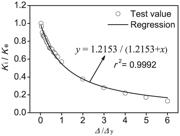
Stiffness degeneration.
It can be found from Figure 12 that the stiffness of test frame decreases obviously at the beginning stage of the loading. When cracks appear on the beam, the stiffness reduces to less than 50% of its initial value. After the frame behaves nonlinearly, the rate of stiffness degeneration begins to slow and no abrupt changes can be observed during the whole test.
A mathematical expression for describing the stiffness degradation can be obtained by regression analysis below

where y is Ki/Ke; x is Δ/Δy; Ke is the elastic stiffness, which is calculated by the initial load divided the displacement corresponding to the initial load in the load-control loading stage; a is the regression factor, which is equal to 1.2153.
Energy dissipation capacity
Equivalent damping ratios, that is, he =S(OBE+ODF)/(2π·S(DAB+BCD)), in which S(OBE+ODF) is the total area of the triangles of OBE and ODF, and S(DAB+BCD) is the area of the hysteresis loop of DABCD, for evaluating the energy dissipation capacity calculated from the load–displacement hysteretic loops are shown in Figure 13. Figure 14 gives the equivalent damping ratios versus the top lateral displacement corresponding to the test frame and the contrasting frame investigated by Chen et al. (2014c). As above-mentioned, in the displacement-controlled cycles, the frames in this test and reported by Chen et al. (2014c) were pushed and pulled at certain amplitude of displacement for three times. In order to establish a comparison basis, the equivalent damping ratios within the first cycle are adopted in Figure 14. It can found that regardless of RCA content, the energy dissipation capacity of circular CFST column–RC beam frame is generally larger than that of square CFST column–RC beam frame, which confirms that the hysteretic loop of 100% RCA content CFST circular column–RC beam frame envelopes that of 100% RCA content CFST square column–RC beam frame illustrated in Figure 9(b).

Energy dissipation capacity calculation diagram.

Energy dissipation capacity.
Ductility
Ductility is one of the most significant indices to evaluate the cyclic performance of a structure. The displacement ductility coefficient μ can be calculated as the ratio of failure displacement Δf to the yield displacement Δy. The displacement ductility coefficient of the test frame is listed in Table 5, and the μ value is close to 3.0. The displacement ductility coefficients of the frames plotted in Figure 15 indicate that ductility of 100% RCA content CFST column–RC beam frames is much better than that of RC frames, indicating that the confinement provided by outer tubes can offset the brittleness caused by RAC defects, and the outer tubes can also improve the ductility of RAC. In addition, the square 100% RCA content CFST column–RC beam frame has a larger μ value when compared to the circular 100% RCA content CFST column–RC beam frame, with respect to the same failure in these frames. The reason can be explained that the steel ratio (As/(As+Ac)) in the square cross-section in this study is higher than that in the circular cross-section reported by Chen et al. (2014c), and a higher steel ratio can have an effective role on contributing to the ductility of a structure.
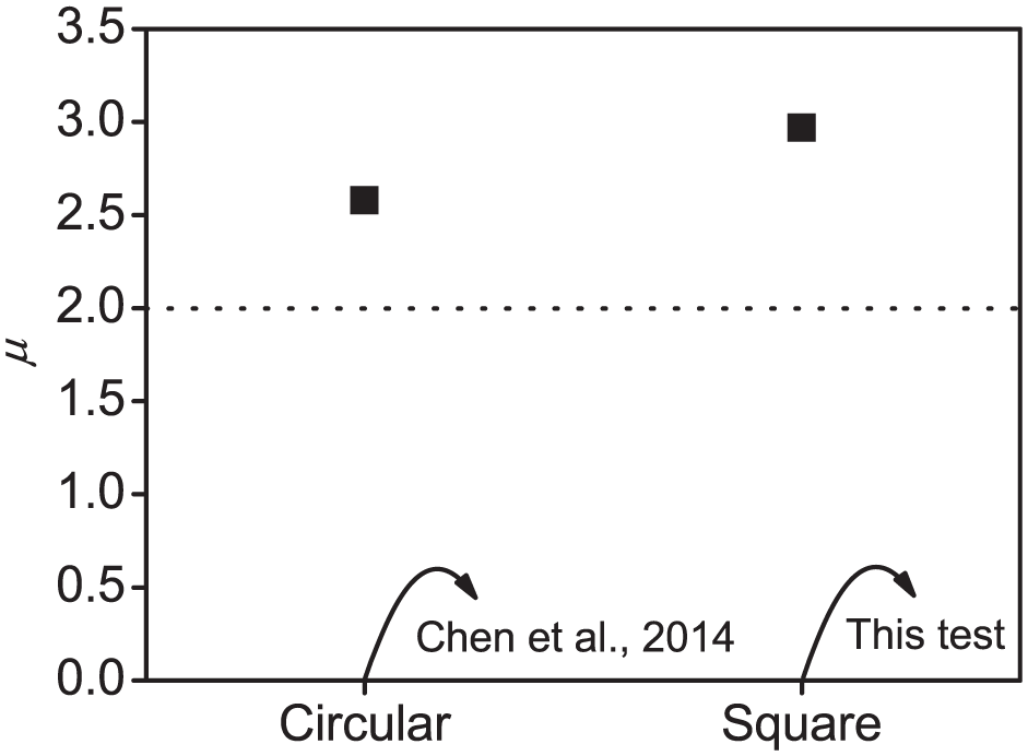
Ductility.
Numerical modeling and experimental verification
General statement
A fiber-based numerical model was developed to predict the seismic behavior of 100% RCA content CFST column–RC beam frames subjected to the constant axial load and the lateral cyclic lateral load. The modeling and nonlinear analyses of CFST columns and RC beams were programmed by employing the fiber element–based SeismoSoft (2014). The inelastic force-based plastic hinge frame element was used to model the CFST columns and RC beams. The uniaxial stress–strain relationships of RAC and structural steels were adopted to endow fiber stresses with fiber strains. The boundary conditions of the frame in SeismoStruct were in accordance with the experimental constraining conditions. All degrees of column base were fixed. The axial loads were applied on the cross-sections of two column tops, respectively, and the cyclic lateral loads were applied to the same point of acting the axial load of a column.
Stress–strain relationship of RAC
Concrete was modeled using the uniaxial nonlinear constant confinement model, initially programmed by Madas (1993), that follows the constitutive relationship proposed by Mander et al. (1998) and the cyclic rules proposed by Martinez-Rueda and Elnashai (1997). This concrete model is defined as “con-ma” in SeismoStruct, and its stress–strain relationship is shown in Figure 16(a). The constitutive relationship in “con-ma” is based on the confinement effect provided by the hoop reinforcement; however, the confinement level of piped concrete is larger than that of concrete restricted by the hoop reinforcement (Choi and Xiao, 2010; Uy, 2001; Xiao and Wu, 2000). As before-mentioned explanations, the confinement factor in “con-ma” should be adjusted in the way of the confinement effect provided by outer steel tubes. To this end, Han et al. (2005, 2007) proposed the calculation method of expressing the enhancement coefficient to consider the confinement factor in concrete-filled steel tube members. The confinement factor (kc) is expressed by


where

Stress–strain relationships of materials in SeismoStruct Software: (a) Mander’s nonlinear concrete model and (b) Monti–Nuti’s steel model.
Xiao et al. (2005) undertook the compressive tests on RAC and reported that the peak strain of concrete was significantly affected by the RCA content but the influence of RCA content on the ultimate strain of RAC can be negligible. Based on the test results, Xiao et al. (2005) suggested the following empirical expression to predict the peak strain of RAC

where

where
In addition, it should be noted that the tensile strength of RAC was neglected in the numerical model.
Stress–strain relationship of structural steel
Structural steel was modeled using the uniaxial steel model initially programmed by Monti et al. (1996), which is able to describe the post-elastic buckling behavior of structural steel under compression. It uses the Menegotto and Pinto (1973) stress–strain relationship together with the isotropic hardening rules proposed by Filippou et al. (1983) and the buckling rules proposed by Monti and Nuti (1992). An additional rule proposed by Fragiadakis et al. (2008) is also introduced, for higher numerical stability/accuracy under transient seismic loading. This steel model is defined as “stl-mm” in SeismoStruct, and its stress–strain relationship is shown in Figure 16(b).
Experimental verification and discussion
The geometric and material parameters of experimental frames were collected from the test information reported in Chen et al. (2014c) and this paper is to carry out the simulation of seismic behavior of CFST column–RC beam frames employing 100% RCA content. Figure 17 shows the lateral load–displacement hysteretic curves of circular and square frames obtained from the measurement and simulation, respectively. It can be observed from Figure 17 that there is a good agreement between numerical simulations and experimental measurements, and especially, the mean ratio of experimental ultimate load to simulation ultimate load (Pu,t/Pu,s) is 0.998, which means that it is acceptable to predict the seismic behavior of 100% RCA content CFST column–RC beam frames under cyclic lateral loads.

Comparison of hysteretic curves between experimental and numerical results.
Conclusion
This article discusses the experimental results of the seismic behavior of square CFST column–RC beam frame realized employing 100% RCAs. The results show that:
The frame failed at the end of beams then occurred slightly local buckling at the bottom of columns, which is characterized in a manner of “strongest joint, stronger column, and weaker beam.”
From the hysteresis loops, the load carrying capacity and energy dissipation capacity points of view, the seismic performance of the circular 100% RCA content CFST column–RC beam frame reported in the existing study are superior to that of the square 100% RCA content CFST column–RC beam frame, which confirms that confinement level offered by circular steel tubes is much higher when compared with square steel tubes under the same parametric conditions.
The displacement ductility coefficients among the test specimen in this test and the reported frame in the literature prove that the 100% RCA content CFST column–RC beam frames have a much better ductility when compared with the ductility of conventional RC frames.
A computer-assisted program model for the nonlinear analysis of 100% RCA content CFST column–RC beam frames was developed to emphasize the effect of RCA content on the behavior of RAC and the confinement effect provided by outer tubes on core concrete. And it was demonstrated that the developed numerical model can accurately simulate the seismic behavior of 100% RCA content CFST column–RC beam frames.
It can be concluded from this study that the CFST column–RC beam frames employing RCAs have remarkable seismic performance, and it is feasible to apply and popularize RAC into CFST structures in seismic regions.
Footnotes
Declaration of Conflicting Interests
The author(s) declared no potential conflicts of interest with respect to the research, authorship, and/or publication of this article.
Funding
The author(s) disclosed receipt of the following financial support for the research, authorship, and/or publication of this article: The research reported in this article was supported by National Natural Science Foundation of China (nos 51708289 and 51578163), Postdoctoral Science Foundation of China (no. 2017M611796), High Level Innovation Group and Outstanding Scholar Program Project of Guangxi High Education (no. [2017]38) and Opening Project of Guangxi Key Laboratory of Disaster Prevention and Structural Safety (no. 2016ZDK003).