
Abstract
In this article, experiments focusing at the influence of steel–concrete bond damage on the dynamic stiffness of cracked reinforced concrete beams are reported. In these experiments, the bond between concrete and reinforcing bar was damaged using appreciate flexural loads. The static stiffness of cracked reinforced concrete beam was assessed using the measured load–deflection response under cycles of loading and unloading, and the dynamic stiffness was analyzed using the measured natural frequencies with and without sustained loading. Average moment of inertia model (Castel et al. model) for cracked reinforced beams by taking into account the respective effect of bending cracks (primary cracks) and the steel–concrete bond damage (interfacial microcracks) was adopted to calculate the static load–deflection response and the natural frequencies of the tested beams. The experimental results and the comparison between measured and calculated natural frequencies show that localized steel–concrete bond damage does not influence remarkably the dynamic stiffness and the natural frequencies both with and without sustained loading applied. Castel et al. model can be used to calculate the dynamic stiffness of cracked reinforced concrete beam by neglecting the effect of interfacial microcracks.
Introduction
Considering the low tensile strength of concrete, cracking may appear in reinforced concrete structures due to in-service loading, early age restrained shrinkage, and so on. Cracking-induced damages lead to a reduction in the stiffness of reinforced concrete members, which influences both static behavior and dynamic response of the structures (Deng et al., 2014; Zhao et al., 2016).
The stiffness
For static loading, when the applied bending moment is larger than the cracking bending moment, primary cracks form in the tensile zone of the beam weakening the moment of inertia at the cracked section resulting in the reduction of the overall stiffness of the beam. Due to the bond between the reinforcing steel bars and the concrete, the tensile concrete between the primary cracks continue to carry a part of the tensile stress and, as a result, contribute to the stiffness of the beam. This phenomenon is known as tension stiffening. When the applied bending moment is increased further and becomes larger than the so-called cover-controlled cracking moment, microcracks develop at the interface between tensile reinforcements and concrete leading to a steel–concrete bond damage and reducing the tension stiffening effect (Wu and Gilbert, 2009). Castel and François (2011) experimentally observed steel–concrete interfacial microcracks under static loading and measured the reduction in static stiffness
Using Castel et al. model, Xu and Castel (2016) studied the effect of steel–concrete bond damage on the dynamic stiffness of cracked reinforced concrete beams under low-amplitude vibration. It was found that bond damage appears not to be relevant to the dynamic response. The level of stress in the steel was very low under low-amplitude vibration. As a result, the dynamic stiffness
In this article, experiments focusing at static and dynamic stiffness of cracked reinforced concrete beams are reported. A total of two cracking damage levels were considered: low and high. For low damaged level, only primary cracks were formed due to the applied bending moment. For heavy damage stage case, steel–concrete bond damage between the primary cracks was created. The static stiffness
Experiments
The experiment includes two reinforced concrete beams labeled B1 and B2. Both beams were priorly subjected to cycles of loading and unloading to create cracks and bond damage. Compared to previous study by the same authors (Xu and Castel, 2016), the natural frequency of the beams was measured under sustained loading instead of testing the beams unloaded. The sustained load applied was equal to the one used to create cracking and bond damage during the preliminary cycles of loading and unloading. Hence, the bond damage was expected to be sufficiently simulated during the dynamic test.
Test specimens
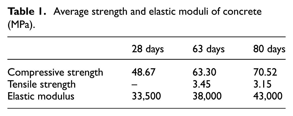
As shown in Figure 1, B1 and B2 had the same dimensions (length of 3500 mm and 400 × 300 mm2 rectangular cross section). The only difference between B1 and B2 is the tensile reinforcement. The main longitudinal reinforcing bars in B2 are ribbed bars of 16 mm diameter with a reinforcement ratio of 0.56%. B2 is a typical lightly reinforced concrete beam, for which the tension stiffening effect and the bond between steel and concrete play a more important role in the stiffness after cracking compared to the beams with high reinforcement ratio (Gilbert, 2007). The diameter of the tensile reinforcement of B1 is 18 mm, leading to a reinforcement ratio of 0.71%. The cover to the main reinforcing bars was 35 mm for both beams. The density of the beams was 2570 kg/m3. The compressive strength and elastic moduli of the concrete at 28, 63, and 80 days are given in Table 1. The average yield and ultimate stress of reinforcing bars were 450 and 620 MPa, respectively. The average elastic modulus of the reinforcing bars was 205.8 GPa. The beams were demolded 24 h after casting and moist cured until the load tests commenced. Beam B1 was tested at 63 days, and beam B2 was tested at 80 days.
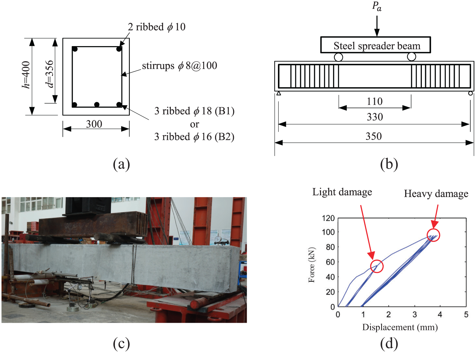
Static loading test: (a) cross section (mm), (b) loading arrangements, (c) loading setup, and (d) damage cases.
Average strength and elastic moduli of concrete (MPa).
Experimental program
The two pinned supports were set with a distance of 3300 mm for the static tests as shown in Figure 1. The experiments consisted of the static cycles of loading and unloading, the natural frequency test, and finally the failure loading. As shown in Figure 2, the experimental program was as follows:
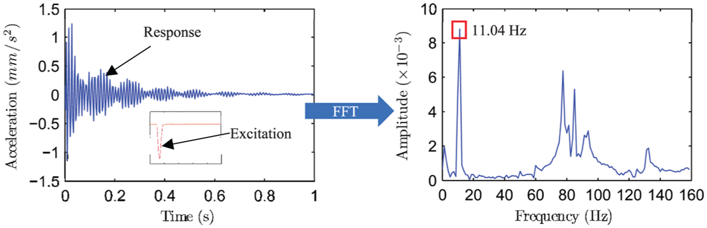
Step 1: Undamaged beams were supported by cables in a quasi-free–free configuration as shown in Figure 3(a). The supporting points were located at the bottom of the beam with the distance of 82.5 cm from the end of beam, which are the inflection points of the first bending mode. A point excitation was impacted at the top side at mid-span of the beam. The response of the beam was measured using an accelerometer located at the top of the beam as shown in Figure 3(a). Using fast Fourier transform (FFT), the natural frequency of the beam was calculated as shown in Figure 4.
Step 2: Both beams were loaded in four-point bending configuration using a hydraulic actuator as shown in Figure 1. For the lightly damaged level, the maximum applied load
Step 3—low damage: After completing the static cycles of loading and unloading, beams were subjected to a sustained load equivalent to 78 kN using two steel rails. By moving the steel rail along the span of the beam, the maximum applied moment could be precisely adjusted. To ensure no extra cracking or steel–concrete interface damage were created due to the additional mass added, only two levels of mid-span bending moments were adopted: 17.55 and 29.25 kN m corresponding to the two load cases named S1 and S2, respectively. In each load case, the natural frequency of the cracked reinforced concrete beam carrying the additional mass loading was measured as described in step 4.
Step 4: In this stage, a point excitation was impacted at the bottom side of the beam. The time histories of the impact excitations were recorded, and the response of the beam was measured using an accelerometer located at the top of the beam as shown in Figure 3(b). Using FFT, the natural frequency of the beam under static loads was calculated as shown in Figure 4.
Step 5—heavy damage: The beams were loaded further using the same setup described in step 2 to create the heavy damage. The maximum applied load
Step 6: Repeating the natural frequency test as described in steps 3 and 4. For the heavily damaged beams, the sustained applied bending moments were 40.95 and 52.65 kN m, corresponding to the load cases named S3 and S4, respectively. The bending moment in case S4 was very close to the maximum applied bending moment used to create the steel–concrete bond damage in step 5.
Step 7: Finally, the beams were loaded up to failure using the same four-point bending system as shown in Figure 1.
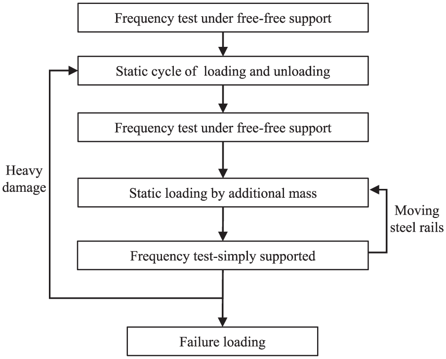
Experimental program.
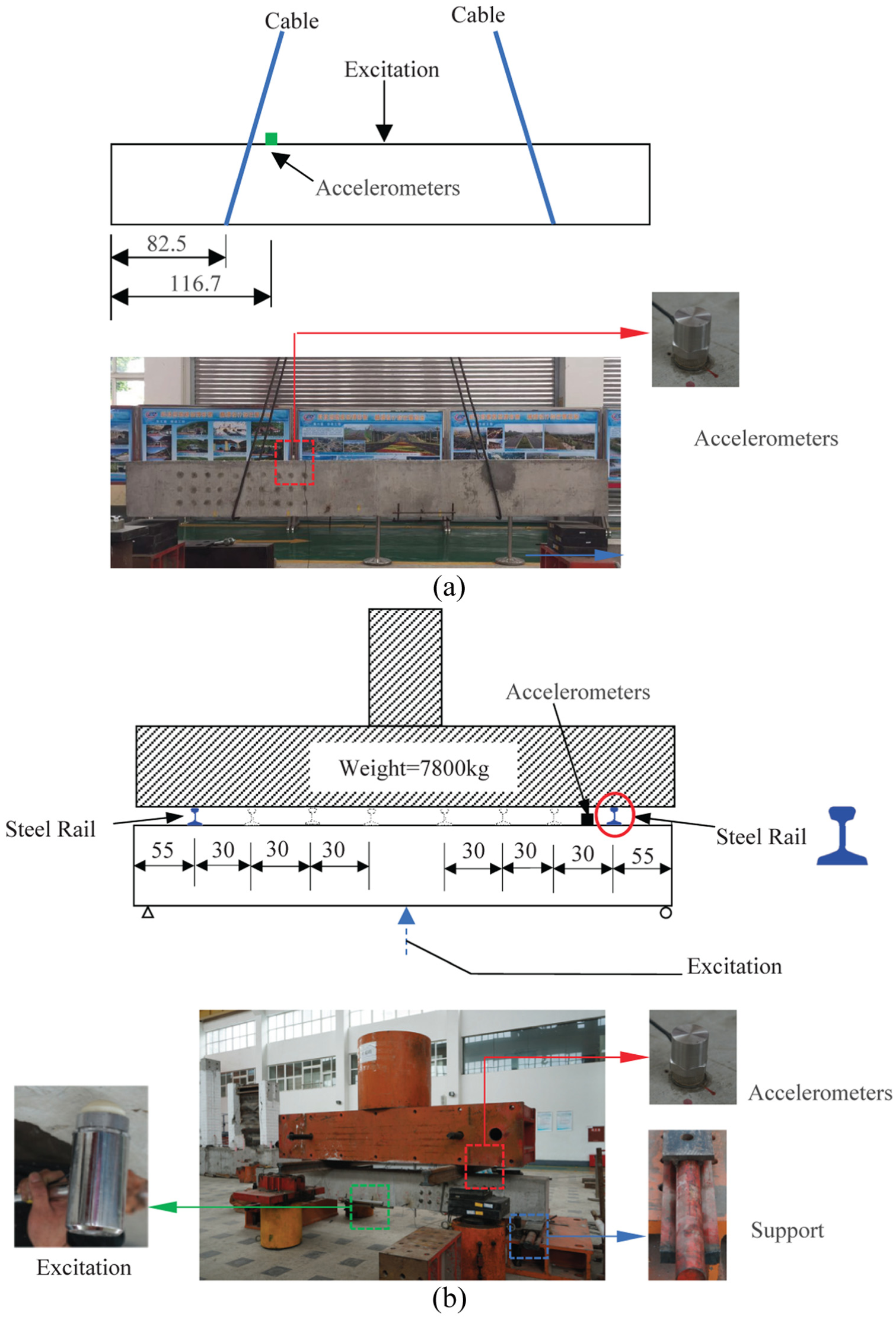
Natural frequency test on (a) the beam supported by cables and (b) the simply supported beam.
Natural frequency analysis.
Experimental results
Static cycles of loading and unloading
The load–deflection responses for two beams including the cycles and the failure are plotted in Figure 5. To show the response of the beams under the cycles of loading and unloading clearly, only the displacements up to 12 mm were plotted in Figure 5. The ultimate loads of B1 and B2 were 282 and 263 kN, respectively. For both beams, the cycle history was typical of in-service load levels (i.e. less than 50% of the ultimate load (Castel et al., 2014).
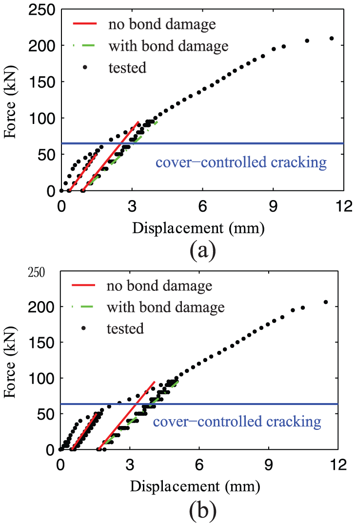
Load–deflection response under cycles of loading and unloading: (a) B1 and (b) B2.
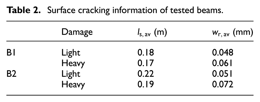
The cracking patterns of both B1 and B2 are illustrated in Figure 6. In Figure 6, the cracks of lightly and heavily damaged beams are plotted in solid lines and dotted lines, respectively. Additionally, the average spacing of the cracks
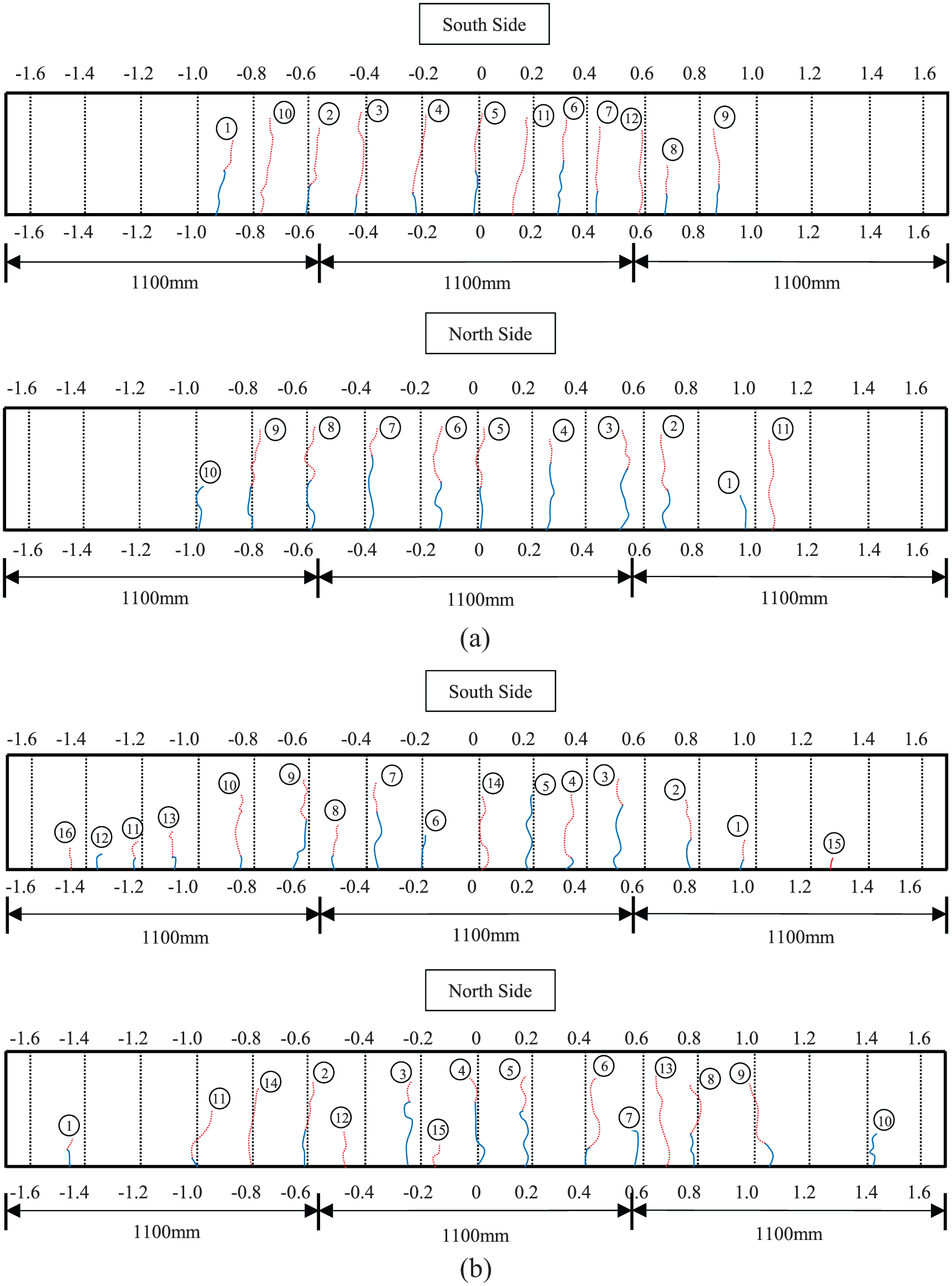
Surface cracking patterns of (a) beam B1 and (b) beam B2.
Surface cracking information of tested beams.
Natural frequency test
The natural frequencies measured for all loading levels and all beams are listed in Table 3. It can be seen that the frequencies of both beams are considerably decreasing after cracking with an average reduction of 32.42%. As shown in Figure 6, visible surface primary cracks were observed on the lightly damaged beams leading to the stiffness reduction. However, although more visible surface primary cracks were created and existing cracks propagated (Figure 6), only a marginal reduction in the natural frequency was observed between the lightly and heavily damaged beams in cases free–free supported, S1, and S2. The average reduction ratio was about 7.69%.
Experimental natural frequency of B1 and B2 (Hz).
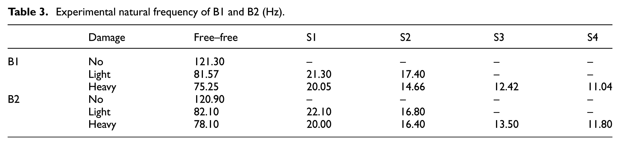
As shown in Table 3, the natural frequencies of both beams decreased from cases S1–S4. One of the main reasons is that the location of the attached mass vibrating with the beam was close to the mid-span. Another possible reason is the influence of the steel–concrete bond damage. Analysis of the results using Castel et al. (2014) model is presented in the next section, allowing to identify the influencing parameters leading to the reduction in both static and dynamic stiffness.
Modeling and discussion
Modeling the moment of inertia distribution
The distribution of stiffness along the beam
In this article, along the uncracked parts of the beam, the overall stiffness is assessed using the gross moment of inertia
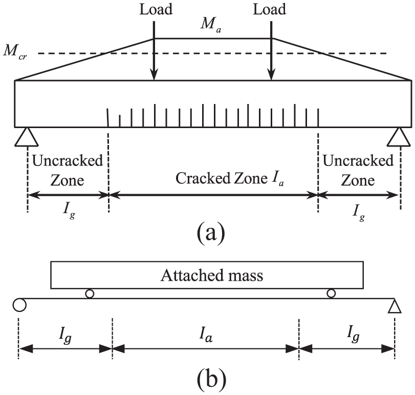
Simulation models: (a) assembling the moment of inertia and (b) vibration model with additional mass.
Castel et al. (2014) model is based on a linear steel–concrete bond between the cracks. The linear distribution of the bond stress
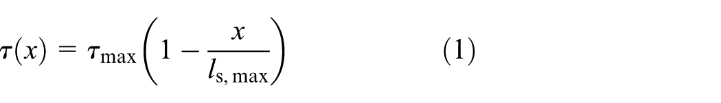
where
According to the equilibrium between the axial force and the shear force, the tensile steel and concrete strains can be written as


where

For excessive service loads, cover-controlled cracks occur at the steel–concrete interface leading to a bond damage (Wu and Gilbert, 2009). A scalar variable

The bending moment

where
When a beam is at the stabilized cracking stage, compared to the whole span of the beam,

where
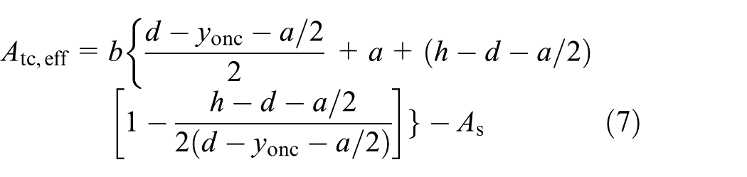
where
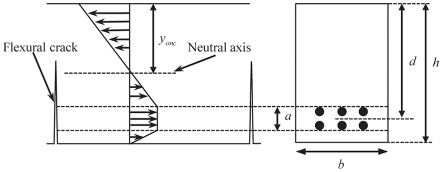
Stress distribution in the concrete in uncracked cross section.
Substituting equation (4) into equation (6) yields
where
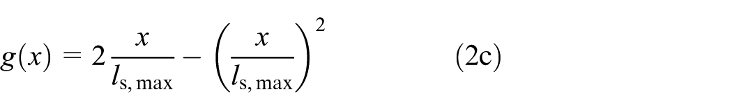
Assuming that the bending moment is constant along

Substituting equations (2), (5), and (8) into equation (9),
For a rectangular section, the depth to the neutral axis

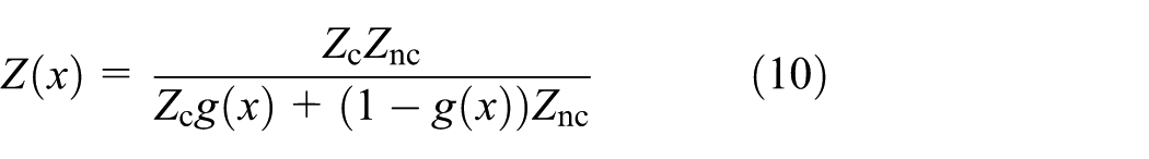
Using equation (11), the moment of inertia distribution
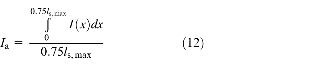
The analytical solution of equation (12) for the rectangle beam was proposed by Xu and Castel (2016). It can be seen that the variable
Bond damage variable
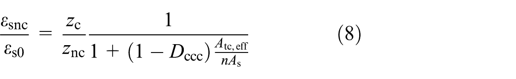
In Castel et al. (2014) model,
where

where
When
Static stiffness analysis
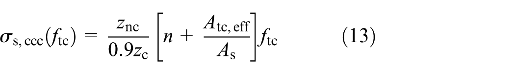
According to equation (5), the bending moment at the cracked cross section can be calculated as

Implementing equation (13) into equation (15), the bending moment
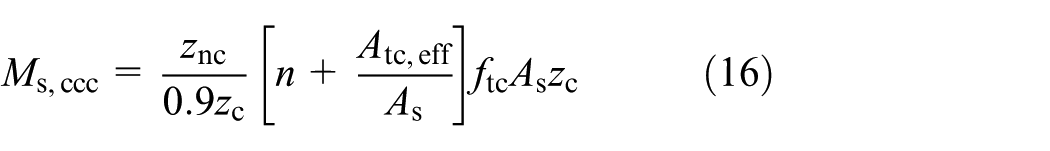
According to equation (16), the criteria for cover-controlled cracking of beams B1 and B2 are
As shown in Figure 5, for the light damage loading level, the maximum applied load (equal to 50 kN) is less than the cover-controlled cracking criteria for both beams. Meanwhile, for the heavy damage case, the maximum applied load (equal to 95 kN) is much larger than the cover-controlled cracking criteria for both beams. Hence, in the simulation, the steel–concrete bond damage had to be considered for the heavily damaged beam only. According to the model mentioned above, the distributions of the average moment of inertia were calculated and are plotted in Figure 9. For the sake of comparison, the calculated average moment of inertia distributions without considering the steel–concrete bond damage for the heavily damaged beam are plotted in Figure 9 as well. It can be seen in Figure 9(a) and (c) that the average moment of inertia for the cracked zone was reduced by approximately 60% due to cracking damage, compared to the gross moment of inertia
Distribution of the average moment of inertia
The distribution of the average moment of inertia is shown in Figure 7(a). The responses of beams B1 and B2 under static cycles of loading and unloading were simulated and plotted in Figure 5. The static stiffness of the beams were deduced from the load–deflection results and compared to the model predictions (Figure 10). A good agreement can be found between the experimental and simulated results using Castel et al. model in Figures 5 and 10 except if neglecting the steel–concrete bond damage in the heavily damaged cases (inertia
Comparison between measured and calculated static stiffness of the damaged beams (
Dynamic stiffness analysis
Free–free supports
The natural frequency of the damaged beams supported in quasi-free–free system were calculated using the average moment of inertia
Comparison between measured and calculated natural frequencies of the damaged beams in the quasi-free–free boundary configuration.
Simple supports with sustained loads
In the previous natural frequency test (free–free supports), the amplitude of the excitation and applied load were low. As a result, it was assumed that the interfacial microcracks were closed, and the bond deterioration was not relevant to the vibration response (Xu and Castel, 2016). In this test, similar amplitude of the excitation was applied to the beam. However, the natural frequencies were measured under sustained loading. The maximum sustained loading applied led to a bending moment
The simulation model shown in Figure 7(b) was adopted to calculate the natural frequency of the beams including the additional mass. The simulated results for the lightly damaged beam are plotted in Figure 12. The average error ratio is only about 4%.
Comparison between measured and calculated natural frequencies of the lightly damaged beams under sustained loading.
For heavily damaged beams, the natural frequencies were calculated using the average moment of inertia
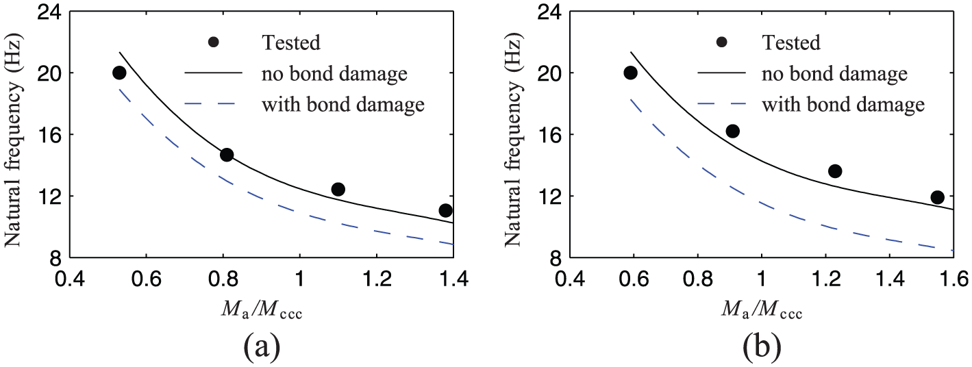
Comparison between measured and calculated natural frequencies of the heavily damaged beams under sustained loading: (a) B1 and (b) B2.
Conclusion
The presented work explored the influence of steel–concrete bond damage on the dynamic stiffness of cracked reinforced concrete beams in free vibration configuration using both experiment and analytical models and led to the following conclusions as follows:
The steel–concrete bond damage affects the static stiffness of the cracked reinforced concrete beam. In this experiment, compared to the cracked reinforced concrete beam without bond damage between primary cracks, the heavily loaded beam (with bond damage between primary cracks) showed up to 30% decrease in the static stiffness.
The measured natural frequencies of the nonloaded reinforced concrete beams decreased considerably after cracking compared to before cracking with an average reduction of 32.5%. However, only a marginal reduction was observed between the lightly (without bond damage) and heavily damaged (with bond damage) nonloaded beams.
The measured natural frequencies of the cracked reinforced concrete beam with sustained loading decreased along with the increment of the applied load due to the location of the attached mass and the propagation of the bending cracks along the beam.
The experimental results and the comparison between measured and calculated natural frequencies of the cracked beams showed that localized steel–concrete bond damage does not influence remarkably the dynamic stiffness and the natural frequency with or without sustained loading applied.
Castel et al. model can be used to calculate the dynamic stiffness of cracked reinforced concrete beam by neglecting the effect of interfacial microcracks induced bond loss.
Footnotes
Acknowledgements
T. Xu wishes to thank the Key Laboratory of High-Speed Railway Engineering, Ministry of Education, Southwest Jiaotong University, People’s Republic of China, for its support.
Declaration of Conflicting Interests
The author(s) declared no potential conflicts of interest with respect to the research, authorship, and/or publication of this article.
Funding
The author(s) disclosed receipt of the following financial support for the research, authorship, and/or publication of this article: This work was supported by National Key Research and Development Program of China (Grant Nos 2016YFC0802205 and 2016YFB1200401), National Natural Science Foundation of China (projects 51778535, 51778531, and 51778537), and Australian Research Council (projects DP110103028 and DP140100529).