
Abstract
Modern architecture has been challenging the obsolete assumptions of the current fire safety engineering approaches, most of which still rely on the standard fire curve and continue to focus on the fire resistance of isolated single members. It has been observed time and again that buildings designed to the code-required fire performance fail in fires where the fire behaviour is found beyond current understanding. To fill this gap in knowledge and practice and move a step forward towards more rational fire safety engineering approaches, an integrated modelling tool is proposed in this article which is devoted to the implementation of realistic and advanced fire models that can be used routinely in analyses accounting for heat transfer and thermo-mechanical behaviour. Two case studies are presented to demonstrate the tool utility in simulating a tall building subjected to vertically travelling fire and a low-rise building subjected to a localised fire.
Keywords
Introduction
Fire-related horrors continue to occur with alarming regularity such as the tragedy that befell the residents of Grenfell Tower in London on 14 June 2017 with up to 80 fatalities, followed soon after by 64 deaths in Portugal as a result of forest fires. That these tragedies continue to occur in relatively well-managed and affluent economies may suggest to the ordinary citizen that prevailing approaches to fire safety are deficient. Among professionals, it is has long been accepted that fire safety engineering based on the standard fire test is at best inadequate and unscientific and at worst catastrophic. In the opinion of the authors, the root cause of this problem in fire safety engineering is the total inadequacy of the current approaches of estimating expected fire hazard intensity which naturally leads to misleading assumptions, conclusions and engineering decisions. A consequence of the prevailing practice is to occasionally precipitate tragedies like the Grenfell Tower event. The current situation is likely to exacerbate considerably if things do not change, largely because the gap between the practice in fire safety engineering and modern architecture and structural engineering practices is threatening to grow into a chasm. More and more adventurous architecture with taller and taller buildings with vastly different internal spaces (compared to buildings of the past) are mushrooming as a result of rapid urbanisation in emerging high-population regions of the world creating much denser urban environments such as that of Hong Kong. In addition to the increased risk of life loss and property damage that naturally follows from denser packing of people and buildings, these trends are also fundamentally changing the nature of the fire hazard (Dai et al., 2017; Kotsovinos et al., 2013; Stern-Gottfried and Rein, 2012a) and past assumptions of small compartment flashover fires are becoming ever more obsolete. With the number of multiple floor fires in tall buildings increasing (Torero et al., 2014), the popular myth of fire safety engineering practice, that fires can be contained in the compartment of origin, is also dissipating. In addition to the new building boom, the pre-existing older buildings in many large cities are becoming death traps because of deteriorating structural integrity or inadequate fire resistance, such as the Plasco building collapse in Tehran in January 2017 (Hajiloo et al., 2017) killing 16 firefighters and 6 civilians.
Fire is not the only and probably not even the most severe threat to human habitation in urban environments; however, it accounts for a very large portion of losses and mitigation costs on society (Hall, 2014). Structural engineers are responsible for designing buildings and urban infrastructure for safety against a range of hazards, such as earthquake and high wind, both of which have a great deal of uncertainty associated with them in terms of hazard intensity or demand. The hazard intensity, structural response to the hazard and its capacity to meet the imposed demand safely with a predictable level of damage (ideally proportional to the magnitude of demand) are routinely estimated in practice using a wide range of analytical and computational tools available to the contemporary structural engineer. These concepts are thoroughly understood in the profession and appear in various forms in international codes and standards ensuring that all structures have adequate safety against the hazards of earthquakes and wind (at least where authorities are able to enforce compliance with standards). It has been proven time and again that buildings so constructed, such as in Hong Kong, California and Japan, ipso facto provide the required level of performance and hence safety against these two hazards. This unfortunately is not the case for the fire hazard, and unexpected and tragic consequences occur with regularity as mentioned above. Nothing illustrates this better than the horrific events of 11 September 2001 when multiple tall buildings collapsed in the aftermath of the terrorist attacks in New York. The studies carried out by official investigator NIST (2005) conclude that the buildings would have survived the aircraft impact without collapse had it not been for the fires that followed. The obvious question to ask as a corollary to this conclusion is that if any one of the two towers (WTC 1 and 2) had only been subjected to a large accidental fire (not a terribly extraordinary event, as discussed earlier), could it then also have collapsed. This scenario was investigated in a series of studies led by the second author and the result was the discovery of new collapse mechanisms in tall buildings subjected to multiple floor fires (Kotsovinos and Usmani, 2013; Lange et al., 2012; Usmani et al., 2003). Indeed, one of the buildings in New York (WTC 7) that did not suffer any aircraft impact (except from minor damage for falling debris) did collapse because of the fires started following the collapse of WTC 1 (NIST, 2008).
The discussion above naturally begs the question: So what is the alternative to current approaches of fire safety provision in buildings and other infrastructure? It is our contention that a rational framework for engineered fire safety can only be based on a range of idealised fire scenarios, including but not limited to compartment fires, localised fires, travelling fires, facade fires and similarly realistic fire scenarios for infrastructure such as bridges and tunnels. Once a suitable set of scenarios have been developed, a set must be agreed upon in advance based on the structural characteristics in consultation with all stakeholders to engineer safety. This by definition will be a performance-based engineering approach and should be the default approach, contrary to the current situation where prescriptive approaches are used by default and performance-based approaches are options to be exercised under exceptional circumstances when the use of prescriptive approaches is unjustifiable.
European practice is perhaps the most advanced in this respect where Eurocodes allow alternative means of providing fire safety (alternative to the prescriptive approach based on the standard fire test) and also provide physics-based demand models such as compartment fire models based on compartment geometry, fuel load and ventilation characteristics; localised fire models in a compartment when flashover is unlikely to occur; and simplified models for external flaming (where flames from a window impinge upon the external structure). The compartment fire models are based on a compartment size limited to 500 m2. In addition to the simplified models, Eurocode also allows the use of advanced models such as one- and two-zone models or computational fluid dynamics (CFD) simulations.
One of the main limitations that inhibit the use of performance-based approaches is the lack of computational tools that could allow more efficient and less labour-intensive analyses and simulations of structural members, systems and subsystems to a range of realistic fire scenarios. The authors have worked over many years to develop the capability of simulating the thermo-mechanical response of structures subjected to fire in the open source software framework OpenSees and this development work is freely available for all research and commercial use from University of California at Berkeley OpenSees website. The authors are extending their work by developing an OpenSees SifBuilder tool that would allow researchers to carry out a range of scenario-based structural responses to fire simulations conveniently and efficiently. The scenarios currently available are based on idealised fires that are spatially uniform (such as standard and parametric fires representing a post-flashover compartment) and spatially non-uniform (such as localised and travelling fires). This article will provide a description of the SifBuilder tool and demonstrate its utility in simulating structural response to a number of fire scenarios.
Development of OpenSees Thermal
In 1997, an open source software framework, Open System for Earthquake Engineering Simulation (OpenSees) was developed at the University of California, Berkeley (McKenna, 1997). It was initially designed to simulate non-linear response of structural frames under seismic excitations. OpenSees is written in C++ and has an object-oriented architecture, which enables structural engineers to focus on specific objects comprising structural models that have their own attributes and functions rather than just data. Major attributes such as elements, materials, analysis procedures and solution algorithms are designed as individual objects and they can be added into the framework freely by anyone anywhere. In 2009, OpenSees was adopted at the University of Edinburgh to further develop it to perform structural fire analysis (Usmani et al., 2012). Significant contributions in terms of heat transfer and thermo-mechanical classes have been made to the framework in developing the Thermal version of OpenSees, where a loose coupling method is adopted in order to separate the heat transfer analysis from the thermo-mechanical analysis. For the latter, temperature-dependent formulations have been incorporated for frame element and shell elements to account for the thermal effects (Jiang et al., 2015; Jiang and Usmani, 2013), while new temperature-dependant material models for steel and concrete based on Eurocodes (BS EN 1992-1-2, 2004; BS EN 1993-1-2, 2005) are also added to the material library.
OpenSees development for heat transfer analysis
In an event of fire, the thermal impact on structural members is calculated in heat transfer analyses. A heat transfer module has been added into OpenSees to provide such capability, which is able to run one-dimensional (1D) to three-dimensional (3D) heat transfer analyses. The basic architecture of the heat transfer module follows the original OpenSees convention, which stores the modelling objects (heat transfer nodes, elements and boundary conditions) in a HeatTransferDomain and performs calculation in HeatTransferAnalysis. Tool Command Language (Tcl) scripting commands have been equipped for the heat transfer analysis as well, which utilise a mesh tool to discretise the structural members or sections into heat transfer nodes and elements. Commonly used structural materials such as steel and concrete have been added into the material library, and the material library will be routinely updated for new research interests.
As illustrated in Figure 1, the heat transfer problem for a typical composite beam section can be solved in OpenSees by taking account the heat input from fire exposure, heat conduction through the section and heat loss to ambient air. The detailed manual of conducting a heat transfer analysis using Tcl can be found from the website: http://openseesforfire.github.io Usually, heat loss is addressed as heat exchange in the form of convection and radiation, while the fire exposure is modelled as heat flux boundary conditions that consist of convection, radiation and prescribed heat fluxes for heat flux–based fire models. The library of fire models is categorised as idealised uniform fires and non-uniform fires, which will be discussed in detail later in this article. Moreover, the output of heat transfer analysis is applied to fire-impacted elements in the form of thermal action when performing thermo-mechanical analyses.
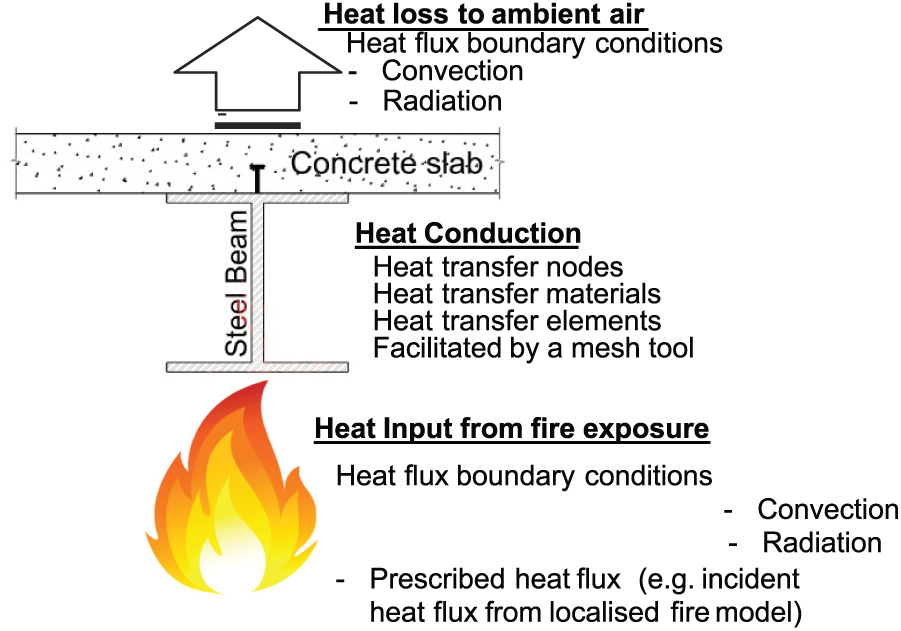
A typical heat transfer problem analysed by OpenSees Thermal.
OpenSees development for thermo-mechanical analysis
In order to model the global behaviour of structures, thermo-mechanical analyses should be performed with the aid of beam-column or frame elements for beams and columns and shell elements for slabs. For each type of thermo-mechanical element, a thermal action is incorporated to define the temperature profile at each time step, while the stiffness and resisting force matrices are formulated by integrating the section response or even further the material responses.
The class hierarchy of beam-column element implementation has been illustrated in Figure 2, where Material, SectionForceDeformation, Element and ElementalLoad are abstract classes (base classes) and also indicate the dependencies between these classes. Thermo-mechanical beam-column elements are derived from the base class Element and keep the general interface and data structure from the beam-column elements for ambient temperature use, such as forming the stiffness matrix and residual forces. The development shown in Figure 2 mainly spreads in the following areas:
The implementation of thermal action, which includes the longitudinal uniform thermal action for two-dimensional (2D)/3D beam-column elements and the non-uniform thermal action using a ThermalActionWrapper or NodalThermalAction;
The thermo-mechanical beam-column elements with displacement- and force-based formulations, which are also available in 2D and 3D;
The fibre-based section for 2D/3D frame element;
The uniaxial material models accounting for temperature-dependent properties, which include different material models for stainless steel, carbon steel and concrete material. Note that these uniaxial materials differ in terms of the the strain–stress relationships, such as idealised elastoplastic model, smooth transition model and Eurocode-suggested models.
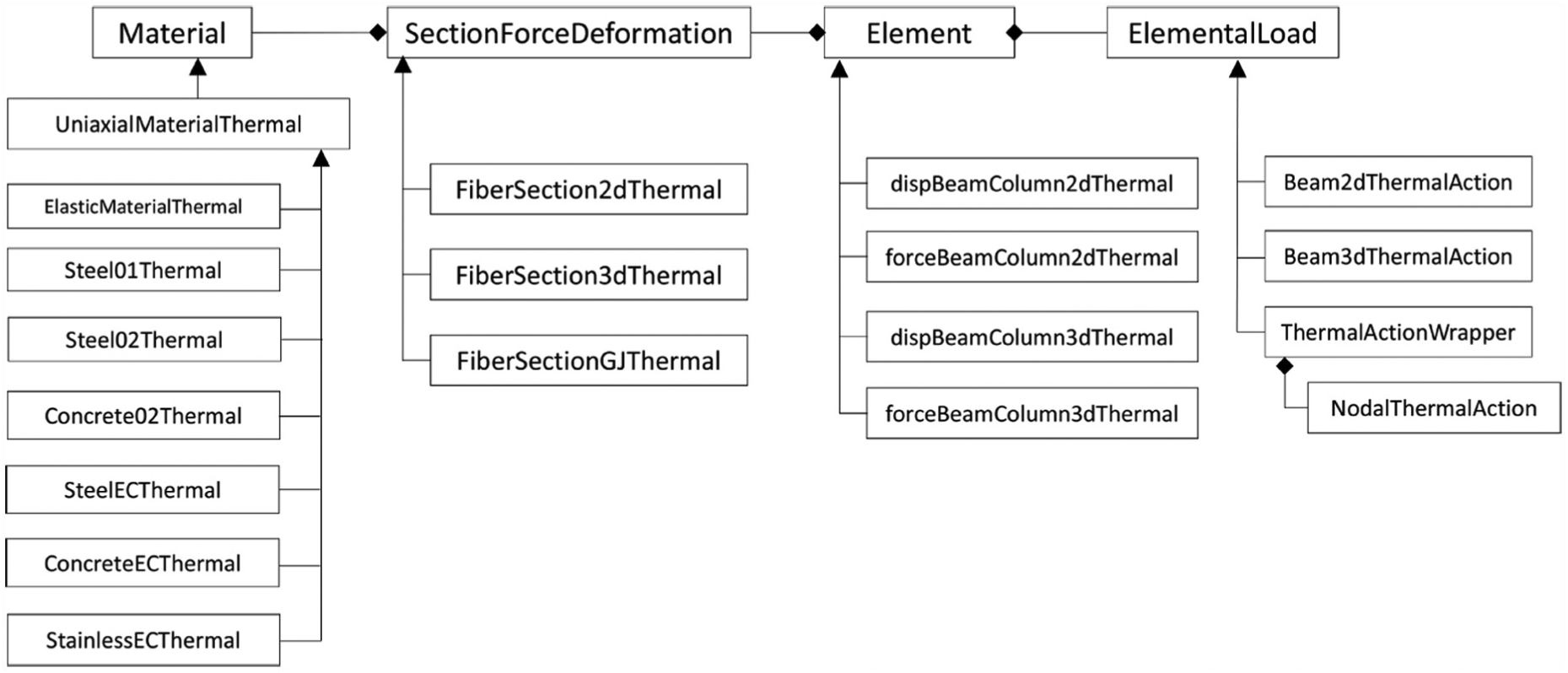
Class diagram of implementing thermo-mechanical beam-column element in OpenSees.
Similarly, the class hierarchy of shell element implementation is presented in Figure 3. The Shell NLDKGQThermal and ShellMITC4Thermal elements are available to discretise a concrete slab into shell elements, which are geometrically non-linear and linear, respectively. These two elements are based on the existing codes in OpenSees (Lu et al., 2017) and have been modified to consider the thermal action, which can be defined with either ShellThermalAction for a uniform temperature distribution along the shell plane or NodalThermalAction and ThermalActionWrapper for a localised distribution. Both shell elements adopt a layered plate section, which can be simply defined as either a MembranePlateFiberSectionThermal of five layers of consistent material, or an advanced Layered ShellFiberSectionThermal which accepts various numbers of layers and different material types for each layer. Currently, the thermo-mechanical versions of multi-axial materials (NDMaterial) for shell elements are available such as elastic models with stiffness degradation and thermal elongation (ElasticIstropic3dThermal); steel models defined as rebar meshes (PlateRebarMaterial Thermal) or plane stress layers (J2PlasticityThermal); and a plane stress form of concrete damaged plasticity model (CDPPlaneStressThermal).
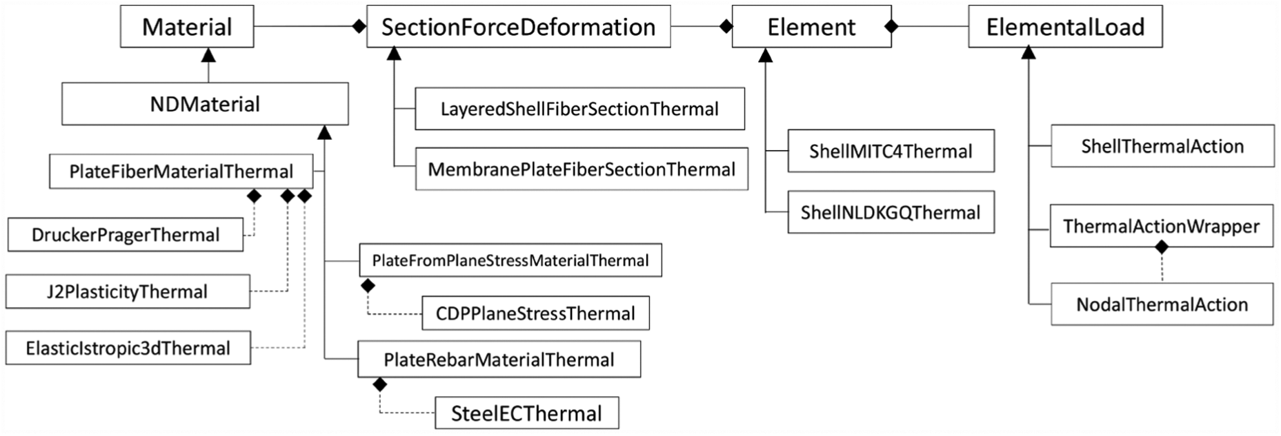
Class diagram of implementing thermo-mechanical shell element in OpenSees.
SIFBuilder: a tool for modelling structures in scenario fires
The SifBuilder (abbreviation of ‘Structure in fire’ Builder) project was started in 2014 and has been under continuous development in the past few years. The tool is designed to integrate the codes of OpenSees Thermal and to help researchers simulate the global response of structures under realistic fire scenarios based on a SIFModel which provides a template to facilitate future integration of the SiFBuilder framework into Building Information Modelling.
Engineering fire models: from standard fire to scenario fires
A number of well-established fire models are integrated into SifBuilder, to provide its users the freedom of using different types of fire scenarios to assist their design calculations. Furthermore, the OpenSees-SifBuilder framework offers a simple interface to develop advanced fire models, which can be as simple as a new time–temperature curve, but can also be as sophisticated as location- and time-dependant heat-flux-based fire models.
Idealised uniform fires are based on the temperature–time curves presented in Eurocode 1 (EN 1991-1-2, 2002), post-flashover fires such as standard fire (ISO-834), hydrocarbon fire and empirical parametric fire are all implemented in SifBuilder. Although these fire models are relatively simple, they are still widely used for both research and design purposes in fire safety engineering. A user-defined fire curve, such as an exponential fire used in Usmani et al. (2003), is also included for convenience of users. These idealised uniform fire models are all assumed to have the same temperature distribution in the entire compartment at a specific time according to Eurocode.
Idealised non-uniform fires are more advanced non-uniform fire models compared to uniform fire models, which are proposed in the context of awareness of non-uniform heating in modern buildings. These non-uniform fire models are capable of producing both spatially and temporally non-uniform temperatures in the compartment. SifBuilder also includes two pre-flashover and localised fire models: Eurocode 1 localised fire model (CEN, 2002) and Society of Fire Protection Engineers (SFPE) localised fire model (Lattimer, 2002). These two localised fire models are regarded to be very efficient for carrying out simulations such as vehicle burning in an open plan car park building. Current travelling fire models such as in Stern-Gottfried and Rein (2012a, 2012b) can be employed in SifBuilder to simulate the travelling fire, and relevant work can be found in the paper by Dai et al. (2017). These more advanced fire models are based upon applying a time history of heat flux at all spatial coordinates of the exposed surfaces of structural members resulting in fully characterising the thermal loading demand on the structure corresponding to any given fire scenario. The authors believe that this approach is able to address the aforementioned need of properly characterising the aforementioned fire hazard intensity associated with realistic fire scenarios. This trend towards better fire hazard characterisation chimes well with emerging fire testing techniques such as the H-TRIS system (Maluk et al., 2015) which offers the potential of experimentally exposing structural members and substructures to heat flux time histories corresponding to idealised non-uniform fire scenarios.
Integrated analysis in SifBuilder
SifBuilder is designed to carry out the full set of analyses which include relatively realistic fire load modelling as mentioned above, heat transfer analysis with automatically configured boundary conditions yielding the thermal loading and the entire structural response to this thermal loading. Since OpenSees is designed as a script-based finite element modeling (FEM) tool, SifBuilder also employs the same Tcl script interpreter and only requires minimal input to build up a model. To hold the structural and loading information, a SIFModel is defined after receiving the input, which allows for further modification of the structural configuration and the loading scenarios to provide the flexibility of adapting the model to fulfil specific needs of the users. The SIFModel shown in Figure 4 serves as a rudimentary Building Information Model for analysing the structural safety in fires.
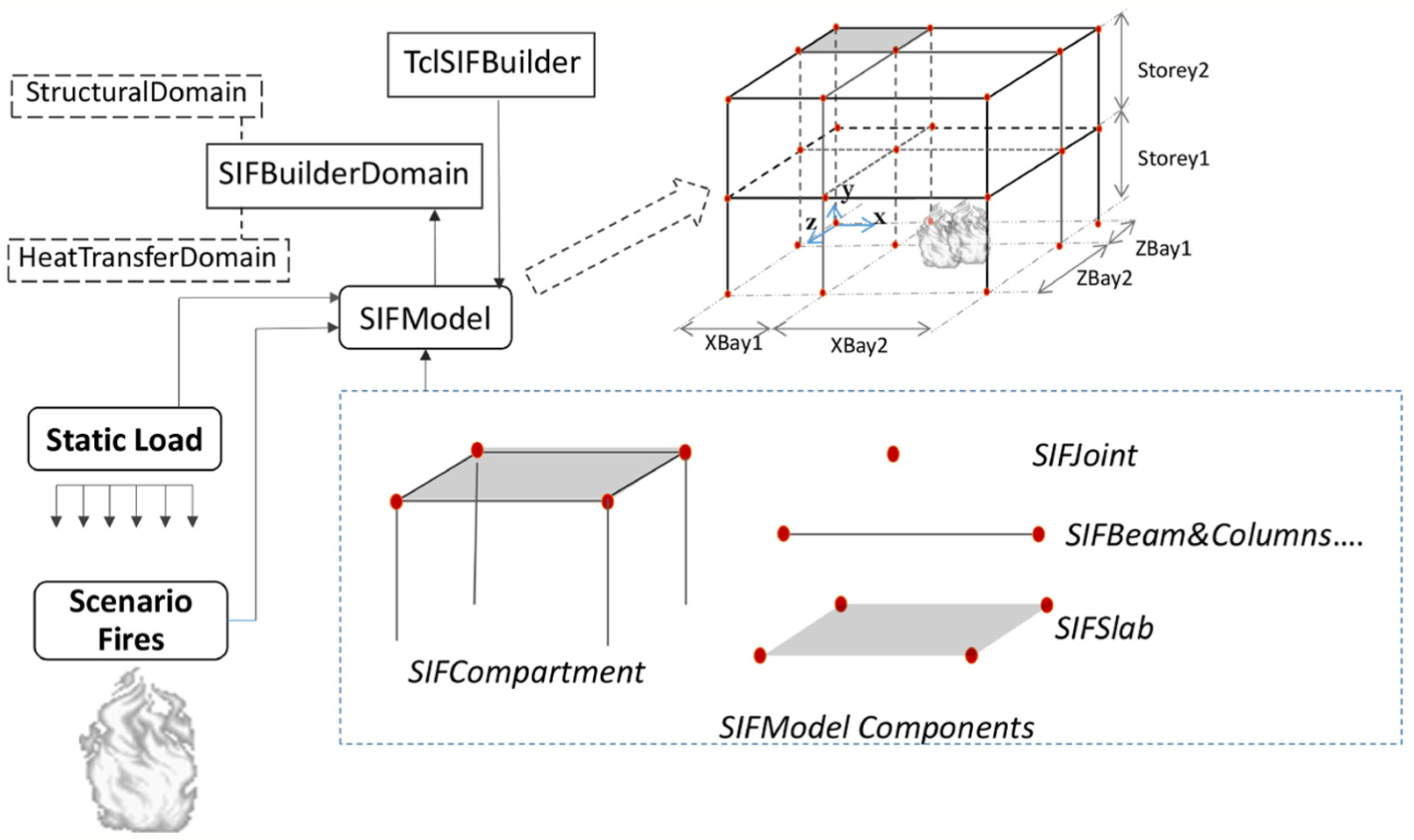
Schematic of SIFModel in OpenSees-SifBuilder.
Unlike commercial packages, neither OpenSees nor SifBuilder has a graphical user interface (GUI). However, it has a script-based user input capability. Similar to other commonly used FEM software, SifBuilder requires the user to input basic structural information for generating the structural model. Procedural scripts are written to specify geometry, materials, loads, heat transfer parameters, fire type, analysis procedures, solution algorithm and output requirements using Tcl. A typical user input script for model generation includes model type definition for identifying the dimensionality of the analysis (from 1D to 3D), geometry of the structure (bay length in each direction in a Cartesian coordinate system), material type and cross-section type for the structural members and boundary conditions for the structural model.
Following model generation, the user defines the structural loading and thereafter the fire loading information. SifBuilder is programmed to hold the thermal loading information throughout the structural analysis. Subsequently, the heat transfer analysis module launches and the nodal temperature histories are automatically mapped to the fibres of the structural mesh. Following the heat transfer analysis, structural analysis is performed on the building, accounting for the degraded material properties. Hence, the output generated will be the result of a thermo-mechanical analysis in response to realistic fire scenarios. Figure 5 shows the flow chart of different operations in the project SifBuilder. The detailed developer information and user manual can be found from the website: http://openseesforfire.github.io
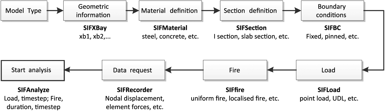
Workflow of using SifBuilder.
Case studies of modelling structures in scenario fires
Brief introduction of case studies
In this section, two case studies are presented to demonstrate the modelling of various fire scenarios and structural configurations within OpenSees-SifBuilder. The first case is to investigate the structural response of a 2D tall building frame subjected to a vertically travelling fire, while the second case is to model a 3D low-rise frame with a stainless steel column subjected to a localised fire.
CASE 1: a tall building subjected to verticaltravelling fire
The tall building model is similarly set up as discussed by Röben et al. (2010) and Kotsovinos et al. (2013) as a generic model, which comprises 10 storeys and each storey is 3 m high. The columns are located on a 10 m × 6 m grid, where the length of all the three bays along the x-axis is 10 m and the width of each of the four bays along the z-axis is 6 m. The columns are protected assuming a 20-mm cementitious coating on a UC 356 × 406 × 46 section, while all the beams are assigned with an unprotected UB 533 × 210 × 92 section. The yield strength of the structural steel used in this model is 300 MPa and the Young’s Modulus is taken as 210 GPa. The floor slabs are 100 mm thick and the compressive strength of the concrete is 35 MPa. A uniformly distributed load of 6 kN/m2 on the floor is employed. As a tall building, the lateral load resistance is mostly provided by the solid concrete core, which is hereby considered as pinned to the plane frame.
The post-flashover fires for each floor are represented by parametric fires as given in EC1 (EN 1991-1-2, 2002). The fire load density is chosen to be 420.0 MJ/m2 for typical office buildings according to EC1. The compartment has a floor area of 240 m2 with an opening factor assumed to be 0.07. The lining material is assumed to be light weight concrete, which has a corresponding thermal inertia of 1159J/m2 s0.5 K. A medium rate of fire growth is assumed which adopts the duration of heating phase t lim = 20 min, which is followed by the cooling phase as described in EC1. Time delays of 600 s are arbitrarily assigned to the upper floors above Floor 2 to represent the vertical spread of fire. The coefficients accounting for the heat transfer from fire to structural members are based on the suggested values in EC1 and the previous studies.
A 2D plane frame model (Figure 6(a)) is created within OpenSees-SifBuilder. As shown in Figure 6(b), the Tcl entry to create such a model is simple in SifBuilder, by deactivating the Z-bay information (out of plane), which is identified by the Tcl interpreter and then stored in SIFModel. Other options are also available to set up models in different dimensions, which is defined along with the corresponding building geometry information. In the case of the x–y plane frame model analysed here, the slab is modelled with beam-column elements and connected to the steel beams using rigid links. Meanwhile, an option is provided for the user to define the beam-column joints as pinned or fixed, which may be extended to semi-rigid connections in the future.
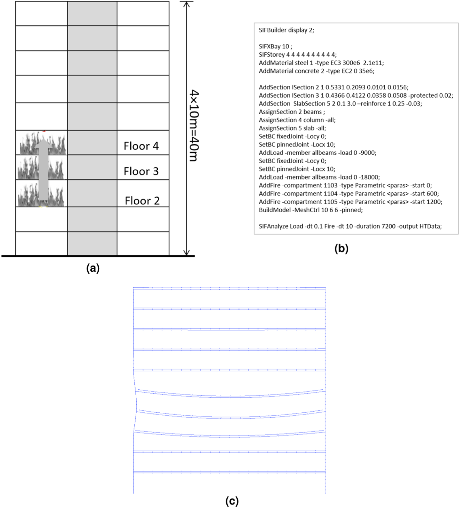
OpenSees-SifBuilder model for tall frame building subjected to vertically travelling fire: (a) plane frame model, (b) Tcl script and (c) finite element model.
The heat transfer analyses for vertically travelling parametric fires are conducted on one cross-section for each structural member only, as a uniform gas temperature assumption is utilised here. The calculated temperature histories of steel beams and the slabs are illustrated in Figure 7(a). A rapid increase is seen in the first 20 mins after ignition at each floor, which is followed by the cooling phase as adopted in the parametric fire model. The concrete slabs retain higher temperature at the bottom, while the steel beams cool off to the ambient temperature (20°C). The vertically travelling fire effect is highly dependent on the time delay as a result of such a simple model, which is certainly not capable of modelling the full complexity of this fire scenario. More advanced models can be developed to address this issue on the basis of new knowledge in the field of tall building fires. More importantly, these potential models can be easily implemented in SifBuilder by defining the time and spatial variations of the gas temperature or incident heat fluxes. The deformed shape of the plane frame during the vertically travelling fire is shown in Figure 8(b). The heated composite beams are subjected to large temperature gradients across section, which leads to significant thermal bowing which pulls back the connected steel columns after an earlier push-out stage due to the beam thermal expansion. The horizontal displacement histories of floor 3 and floor 4 are presented in Figure 7(b), from which the reversal of the beam-column joint can be observed over 1000 s of heating. Moreover, the vertical displacement of the mid-span point of the composite beams are illustrated corresponding to the fire duration. The large floor deflections are due to the thermal bowing initially and later the floor load, as a result of catenary action. It has been shown that this type of multi-floor fire can lead to the collapse of the columns and this phenomenon has been identified as the strong floor collapse mechanism of tall building frames subjected to vertically travelling fire (Kotsovinos et al., 2013).
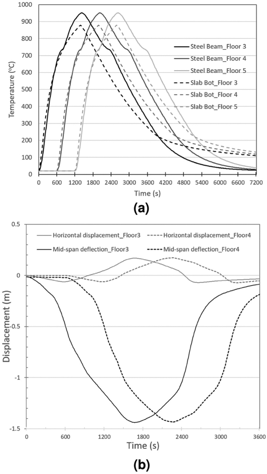
Temperature evolution of steel beams and slab deflection at different floors: (a) beam temperature and (b) slab deflection.
Schematic plan view and finite element model of building model: (a) plan view and (b) finite element model.
CASE 2: a low-rise frame with stainless steel column subjected to localised fire
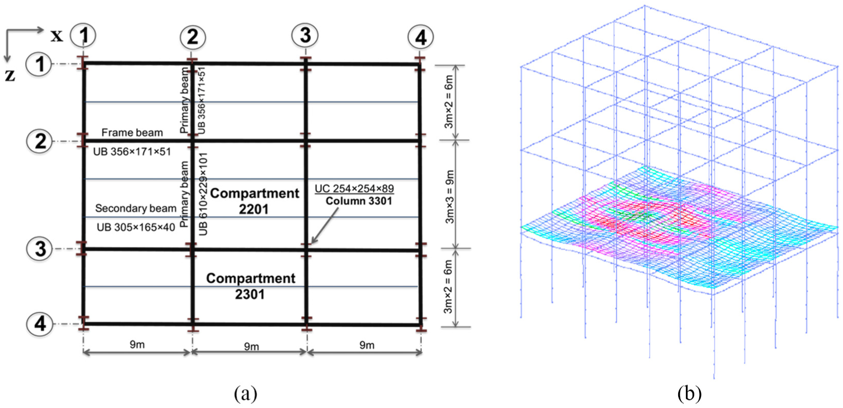
The second case is to model a frame building model as shown in Figure 8, which is similar to the layout of Cardington test building (British Steel, 1999) but only with regular compartments. Along the length direction (x-axis in SIFBuilder), three bays of 9 m length are placed to represent a substructure model with horizontal constraints on the joints. Along the width direction (z-axis in SIFBuilder), the widths of the three bays are 6, 9 and 6 m, respectively, corresponding to the Cardington building.
Primary beams of this building model are of a UB 610 × 229 × 101 section for 9-m span, and the section size reduces to a UB 356 × 171 × 51 section for 6-m span. All the secondary beams are assigned with a UB 305 × 165 × 40 section, and the frame beams along the x-axis are of a UB 356 × 171 × 51 section. All the columns are of a UC 254 × 254 × 89 section. Composite floor slab system was adopted in Cardington test, which comprises a slab with a minimum thickness of 130 mm. In this model, a flat slab is assumed for simplicity and its thickness adopted as 150 mm as an average value of Cardington building. Here it is assumed that a central column (tagged as 3301) will be replaced with a stainless steel section. The tag system simply indicates that it is on the gridline 3 along the x-axis and locates in the third bay along the z-axis. The last two numbers of the tag represent the floor tag which ranges from 01 to 99. The column will be subjected to a localised fire surrounding it and compared to the protected and unprotected carbon steel columns. The localised fire source adopted in this study has a heat release rate of 3 MW, and the nominal diameter is 1 m. The fire plume of such a localised fire can impinge on the ceiling and also result in localised heating of the floor above.
The austenitic grade 1.4571 is adopted in this model to investigate the fire performance of stainless steel members in the context of the global response to a moderate fire. Stainless steel is sometimes preferred by architects in suitable projects due to its high aesthetic value and good durability. Stainless steel exhibits higher thermal expansion than carbon steel, which could be 50% greater as shown in Figure 9(a). Recent research has suggested that stainless steel, especially the austenitic grades, possesses better capability of retaining strength and stiffness at higher temperatures in comparison with carbon steel. The reduction factors for the strength and stiffness of carbon steel and austenitic stainless steel and the variation of these factors corresponding to elevated temperatures are illustrated in Figure 9(b) where stainless steel (grade 1.4571) is presented with its 0.2% and 2% proof strengths (Gardner, 2007). When the temperature goes above 400°C, no rapid decrease occurs in nominal strength and elastic stiffness of stainless steel, unlike carbon steel that is usually believed to lose its strength and stiffness significantly after reaching 400°C. The exhibited better fire performance of stainless steel hereby becomes fascinating as its use may allow significant reduction in fire protection, or potentially no fire protection at all under realistic fire scenarios.
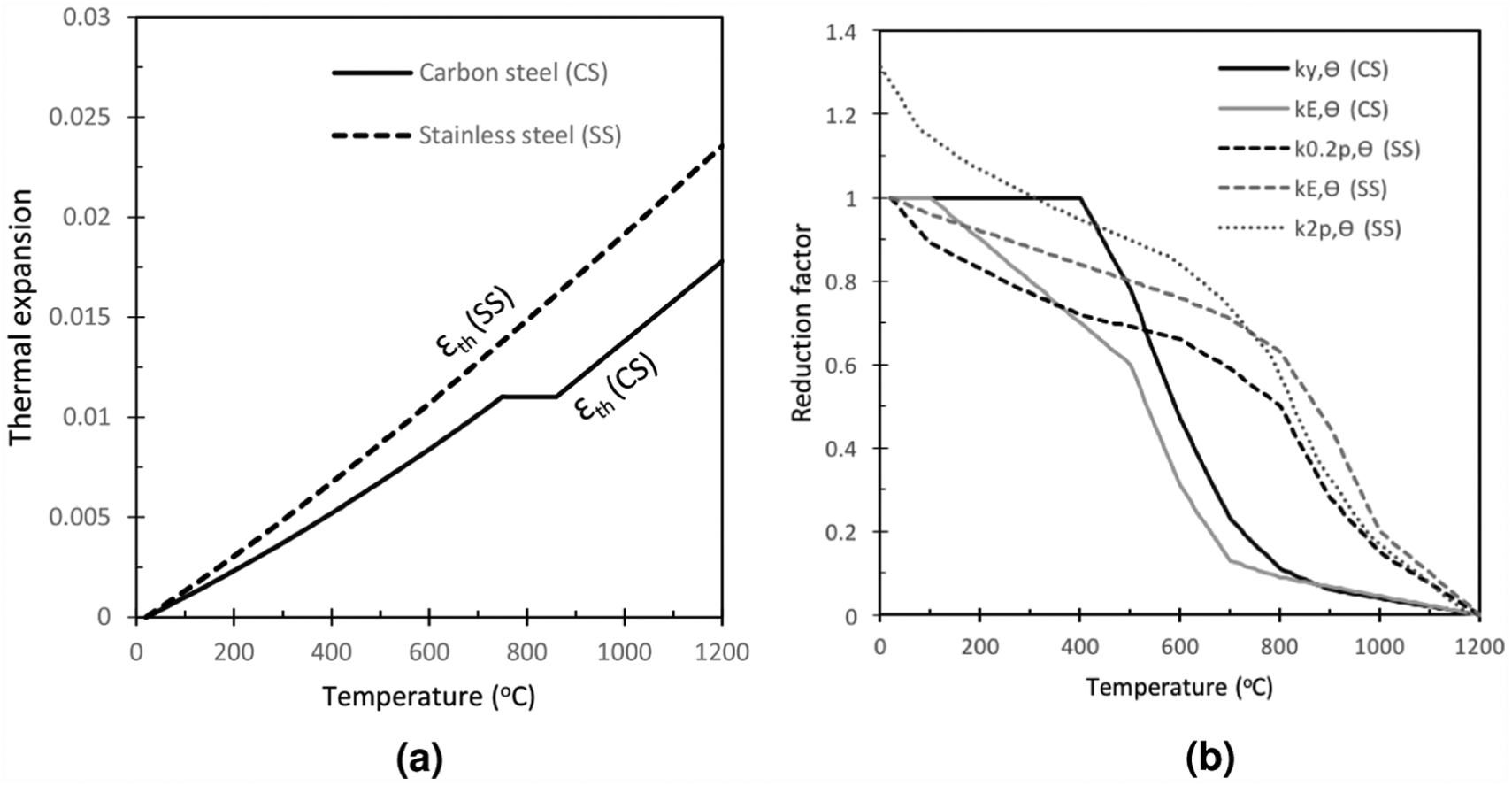
Material properties of stainless steel (grade 1.4571) compared to carbon steel: (a) reduction factors of strength and stiffness and (b) thermal elongation.
The implementation of stainless steel into OpenSees-SifBuilder comprises a heat transfer material class and a thermo-mechanical material class, as well as the necessary keywords added to facilitate the use of Tcl script. The thermal response of the stainless steel column is found to be similar to the carbon steel column while no protection is applied, as shown in Figure 10. A much lower temperature increase can be observed if the column is protected with a 20-mm-thick cementitious coating.
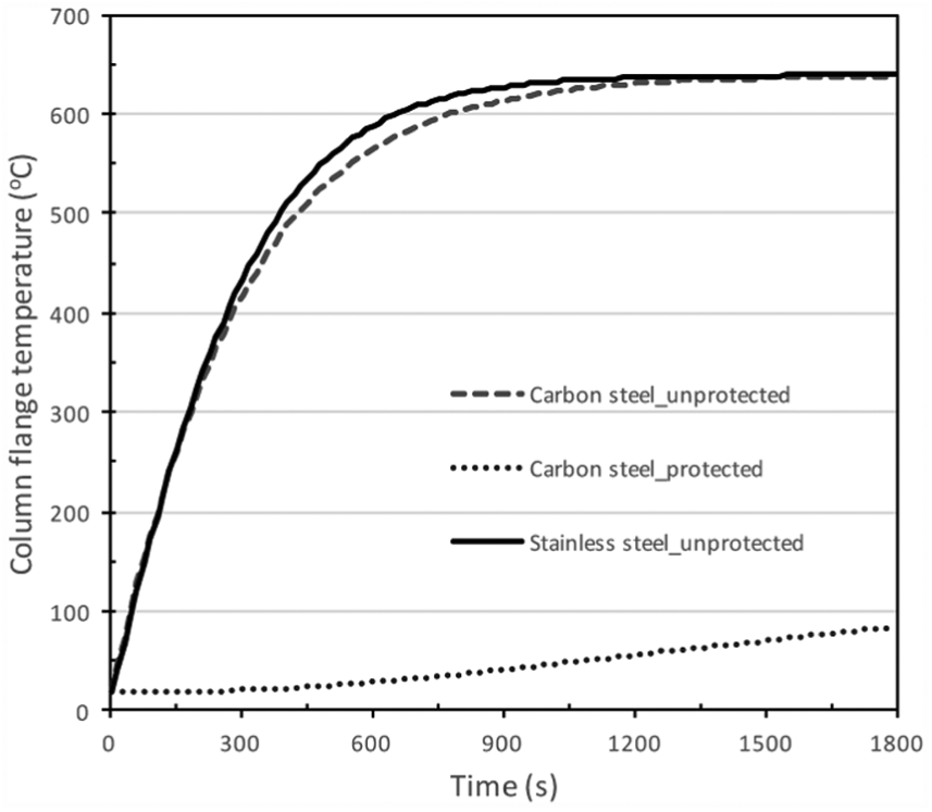
Temperature history of Column 3301 for differnt sections.
The axial deformation of the column 2301 made of various materials is represented as the vertical displacement of SIFJoint 2301 and has been illustrated in Figure 11(a). For unprotected steel columns, the column top displacement increases rapidly because of the heating in the first 300 s. However, the displacement begins to decrease as a result of material softening in the carbon steel column, which is in contrast with the displacement development in the stainless steel column as no significant loss of material stiffness and strength occurs. Meanwhile, the variation of the axial force in the steel column can be found in Figure 11(b). After a period of 400 s of heating, the curves of axial force greatly differ in the unprotected carbon steel and the stainless steel column. While the increase of compression at the early stage is due to retrained thermal expansion, the axial force in the carbon steel column reduces as a result of the strength loss. When the steel column is made from stainless steel, the column axial force remains relatively high since the material retains strength well into temperatures over 600°C. Furthermore, the average axial force in the protected carbon steel column is much lower as the development of thermal expansion is rather limited due to the low-temperature profile. In such a localised fire case, stainless steel column provides consistently better load-bearing capability and the deflection of the composite slab is limited to a low level in the vicinity of the column. However, the high thermal expansion may result in significant connection damage, which is not examined in this article.
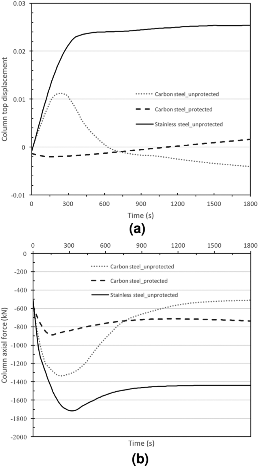
Vertical displacement at the column top and axial force in the column subjected to localised fire: (a) column top displacement and (b) column axial force.
Concluding remarks
Traditional fire safety engineering for structural fire resistance has been gradually moving to a new era where the global structural behaviour in fire is eliciting greater interest and along with it the interest in exploring more realistic and increasingly more complex fire scenarios as our understanding of structural fire behaviour moves forward. OpenSees-SifBuilder is developed in this context and this tool aims to provide an integrated computational environment for structural engineers to quantify the structural safety under various design fire scenarios.
Two case studies are presented in this article to demonstrate the SifBuilder tool. The first case is to model a plane frame subjected to vertically travelling fire as it is a typical scenario for tall building fires. The strong floor collapse mechanism can be observed from the analysis, as a result of thermal bowing and large deflections at multiple floors. The second case study is to investigate the performance of a moment-resisting frame in which one inner column is assigned with a stainless steel section and heated by a localised fire. The stainless steel column experiences a similar temperature rise compared to carbon steel column, while the axial force reaches a high value in stainless steel column as a result of the large thermal expansion and its ability to retain strength and stiffness.
The potential of SifBuilder is not just limited to the cases discussed in this article, a number of scenario fire models can be easily implemented in the framework without significant effort on configuring with the heat transfer and thermo-mechanical analyses. OpenSees-SifBuilder can help structural engineers move from the standard fire curve–based approach and embrace the emerging fire models being developed to represent the realistic fire behaviour.
Footnotes
Acknowledgements
The work presented in this article is based on the development of OpenSees. Dr Frank Mckenna is gratefully acknowledged. The previous students of the corresponding author are acknowledged for their contribution to OpenSees development for modelling structures in fire.
Declaration of Conflicting Interests
The author(s) declared no potential conflicts of interest with respect to the research, authorship and/or publication of this article.
Funding
The author(s) disclosed receipt of the following financial support for the research, authorship, and/or publication of this article: The authors acknowledge funding provided by the Hong Kong Polytechnic University for this research as part of the project “Further Development of OpenSees Structures-in-Fire (SiF) Simulation” (account code 1-ZVJG).