
Abstract
Considering the interaction of flexural moment and shear force in the steel frames with haunch or intermediate beam length and eccentrically braced frames with intermediate link length is a major concern of the structural analysis and design. This article contains two stages. In the first stage, to investigate the moment–shear interaction for the highly ductile steel I-sections, a study is carried out using finite element analysis and a simple and practical relationship is developed. In the second stage, a simple approach based on virtual work method for assemblage of interconnected rigid bodies is employed to consider collapse mechanisms with mixed hinges. Using this approach, the applicability of the proposed relationship is demonstrated for a one-bay portal frame by considering all possible collapse mechanisms including those containing mixed hinges. Some numerical examples are presented using the proposed approach. Results indicate that, in general, the effect of moment–shear interaction on the load capacity of the structures cannot be ignored, and the capacity could be estimated, without using step-by-step analysis. Finally, by satisfying kinematic compatibility requirements and normality condition, simplified relations are derived to estimate post-mechanism deformations of plastic hinges for a prescribed lateral drift.
Keywords
Introduction
Steel frames and eccentrically braced frames (EBFs) are some of the widely used systems in building industry. Inelastic behavior of EBFs depends on the link length. Based on AISC 341-16 (2016a), for links of length
Several researchers have investigated the effect of moment–shear, M-V, interaction on beam capacity. By means of upper and lower bound theorems of plasticity, Drucker (1956) examined a cantilever and a simple beam with rectangular cross sections and developed a moment–shear interaction relationship. Neal (1961a) extended Drucker’s work to consider the axial force effect and obtained a moment–shear–axial forces interaction relationship. He also presented a lower bound solution for I-section beams (Neal, 1961b). Using Neal’s equation, Montuori et al. (2014) presented a procedure for calculating the ultimate end moments and shear forces of intermediate links of EBFs with inverted Y-scheme. By ignoring the effect of vertical load, they also estimated plastic deformation of intermediate links. Basler (1961) derived an interaction relationship for I-section by assuming a simple stress distribution, which had been used in AISC specifications for consecutive years until AISC 360-05 (2005). Liu et al. (2009) obtained a failure criterion for steel member cross sections considering the combination of bending moment shear force and axial force. Kazemi and Erfani (2007a, 2007b, 2009) presented an element with zero or non-zero length that it considers moment–shear interaction. Their model includes multiple and dissimilar yield surfaces with a kinematic hardening rule and a developed non-associated flow rule. Kazemi and Asl (2011) considered moment–shear–axial interaction yield surface in deformation space and included strength and stiffness degradation. They also presented a mixed element based on damage-plasticity. For slender plate girders, Shahabian and Roberts (2008) presented a moment–shear interaction formula which covers a range of web panel width to height ratio from 1 to 2 and slender ratio from 150 to 300. For design of beams with reduced web section connections, an interaction relationship has been presented (Kazemi et al., 2012; Momenzadeh et al., 2017).
Azizinamini et al. (2007) tested eight steel I-girders with simple supports and reported that all the specimens sustained loads more than the predicted values. They state that the moment–shear interaction can be ignored, in practice. Based on the experimental results, White et al. (2008) indicate that the shear and flexural strengths can be calculated without the need for the consideration of their interaction, using ANSI/AISC 360-05 (2005) provisions for the flexural resistance and Basler’s model (White and Barker, 2008) or Cardiff model (White and Barker, 2008) for the shear capacity. Daley et al. (2016) examined moment–shear interaction for welded I-girders with thin unstiffened webs. They concluded that it does not need to consider the moment effect for evaluating of shear strength. Based on their observations, the commentary of ANSI/AISC 360-16 (2016b) states, “Consideration of shear and bending interaction is not required because the shear and flexural resistances can be calculated with a sufficient margin of safety without considering this effect.” On the other hand, Lee et al. (2013) investigated the interaction behaviors of I-girders and developed a new interaction relationship. They concluded that interaction effect cannot be neglected when failure occurred by yielding due to combined bending moment and shear force. By developing simplified approaches, it will not be needed to ignore the flexural shear interaction.
For moment frames, Grigorian and Grigorian (2012a, 2012b) introduced a simplified method to calculate the sequences of the plastic hinges formation and corresponding lateral deformation up to mechanism load. Using theory of plastic mechanism control, Montuori et al. (2015) presented a closed-form design procedure to prevent occurrence of any partial or story mechanisms and to achieve the global-type collapse mechanism. This concept specialized for steel moment frames (Dell’Aglio et al., 2017) and reinforces concrete frames (Montuori and Muscati, 2017).
The contribution of the concrete slab to the combined shear and bending behavior of steel–concrete composite beams have been investigated by several researchers (Liang et al., 2004, 2005; Nie et al., 2004; Vasdravellis and Uy, 2014). They showed that concrete slab significantly improves the combined shear and bending behavior of composite beams.
This study is limited to the highly ductile steel I-section members without considering concrete slab, where their webs could yield, and the effect of moment–shear, M-V, interaction is challenging. This article includes two parts. In the first part, M-V interaction of steel I-section beam is investigated. A new relationship is constructed for M-V interaction using refined inelastic finite element (FE) analysis, based on the modeled samples. The proposed simplified relationship is comparable with the other available ones and is suitable for the plastic analysis of the steel frames. In the second part, the proposed relationship has been used, directly, to predict the collapse load of single-bay portal frame considering all its possible collapse mechanisms, without requiring step-by-step or stage-by-stage nonlinear analysis. A simplified approach is developed to consider collapse mechanisms which include mixed hinges. Also, the possibility of internal plastic hinge development for the beams carrying vertical load is considered, using a simple concept. To show the applicability of the suggested approach, several numerical examples are presented. In general, pre-mechanism plastic deformations in the inelastic hinges depend on the load path and require incremental analysis, but to estimate the post-mechanism plastic deformation of plastic hinges for a prescribed lateral drift, simplified relations are presented.
Numerical study for development of moment–shear yield surface
In order to develop a yield surface relationship for I-section beams in the space of bending moment and shear force, EBFs, with different link lengths were modeled using the nonlinear FE analysis software ABAQUS (2014).
ABAQUS S4R shell element, which is a four nodes shell element using reduced integration method, is utilized for meshing all model geometries. The hourglass phenomenon is controlled by checking the ratio of the total artificial energy to the total internal energy be less than 0.01. Also, mesh convergence study is performed to find the suitable element size for achieving both accuracy of the results and optimal computational time. The nonlinear static-modified Riks method (arc-length method) is applied for the analysis, in which the geometric nonlinearity option is activated. Initial geometric imperfections are introduced into the model based on the first two buckling modes of the models which are calculated by a linear eigenvalue buckling analysis. Accordingly, the effects of large deformation, local buckling, and post-buckling behavior are simulated. The maximum value of initial imperfections of
To verify the modeling techniques discussed above, in a preliminary study, several existing experimental results (Cooper et al., 1964; D’Apice et al., 1966; Nishino and Okumura, 1968; Vasdravellis and Uy, 2014) were used. The first verification study is a simply supported I-section beam, specimen BS-1 of (Vasdravellis and Uy, 2014), which was loaded by a mid-span point load. The beam cross section is IPE330 and the span length is 0.8 m.
Figure 1 presents the curves of shear force versus deflection at the mid-span for the present finite element method (FEM) results and the experimental and the FEM results reported by Vasdravellis and Uy (2014). The comparison shows that the present FE model is able to accurately predict the initial stiffness, ultimate strength, and post-buckling behavior of the specimen (Figure 1). The material stress–strain curve of the steel assumed to be similar to one reported by Kirkland et al. (2015) with yield stress of 358 MPa.
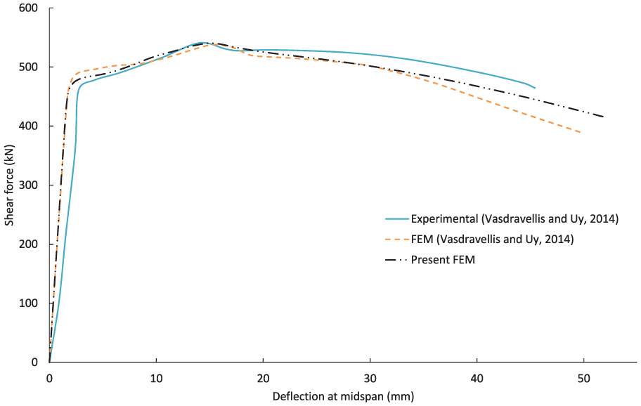
Comparison between the present FEM result and the experimental and FEM results reported by Vasdravellis and Uy (2014).
The second verification study contains three simply supported I-section girder, where each beam has two symmetric panels. The present numerical results are compared with some available experimental results in Table 1. The dimensions and material properties of the specimens are similar to the one proposed by Graciano and Ayestarán (2013) and are reported in Table 1, where a is the distance between transverse stiffeners,
Comparison of the experimental with the present FEM results and material properties and dimensions of the girders.

FEM: finite element method.
EBFs are suitable structures for studying M-V interaction. Therefore, eight EBFs, designed based on ANSI/AISC 341-16 (2016a), were modeled which have different link lengths and stiffeners. In all models, the beam length and column height are 8.0 and 3.6 m, respectively. In each model, the connections of beam to column and the brace to both beam and column are rigid, while the column support is pinned (Figure 2).
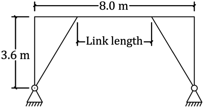
Schematic drawing of EBFs used in FE study.
An ideal elastic-perfectly plastic von Mises material, with
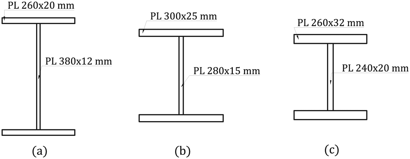
Dimensions of (a) beam, (b) column, and (c) brace sections.
The intermediate and end transverse stiffeners of the links are plates of 380 mm × 124 mm × 12 mm, and 380 mm × 124 mm × 10 mm, respectively. Based on ANSI/AISC 341-16 (2016a), equally spaced intermediate stiffeners are considered on one side of the link web, while end stiffeners are considered on both sides. Table 2 represents the frame link lengths, their corresponding number of intermediate stiffeners, and dominant inelastic response of links based on ANSI/AISC 341-16 (2016a). All frames were pushed, using arc-length method, in which lateral load pattern was applied to both left and right of the frame, while displacement of the link middle point was controlled.
Categorization of the sample EBFs based on ANSI/AISC 341-16 (2016a).

EBFs: eccentrically braced frames.
The target displacement was selected as 1.5 times of the design story drift. The design story drift
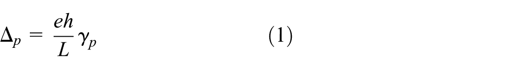
where h, L, and e are column height, beam length, and link length, respectively.
Based on the above assumptions, the eight described EBFs were modeled and analyzed. As an example, for the FE model of the EBF with the link of length 1.7 m, mesh convergence study was resulted in 25,823 elements. Figure 4 represents von Mises stress distribution in the deformed shape of the model. Also, the effect of moment–shear interaction on the deformations can be seen in Figure 4, where the link beam not only rotates but also vertically slips, with respect to the beam outside of the link.
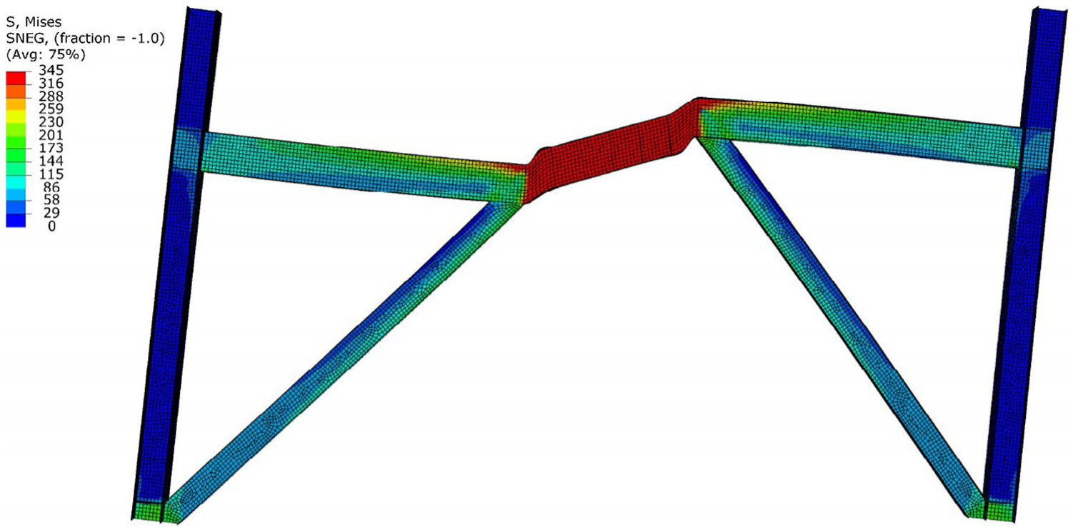
Von Mises stress distribution in a deformed EBF with link of length 1.7 m. The deformations are exaggerated five times.
Proposed moment–shear interaction relationship
Based on the numerical investigation explained in the previous section, a general relationship considering M-V interaction is developed. The ultimate bending moments and shear forces, obtained from the numerical analysis, were normalized by plastic bending moment
By examining the numerical results and other models, equation (2) is proposed
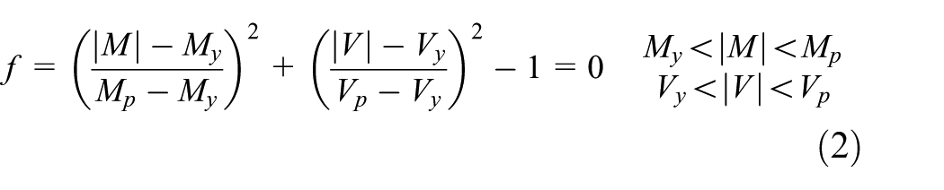
where
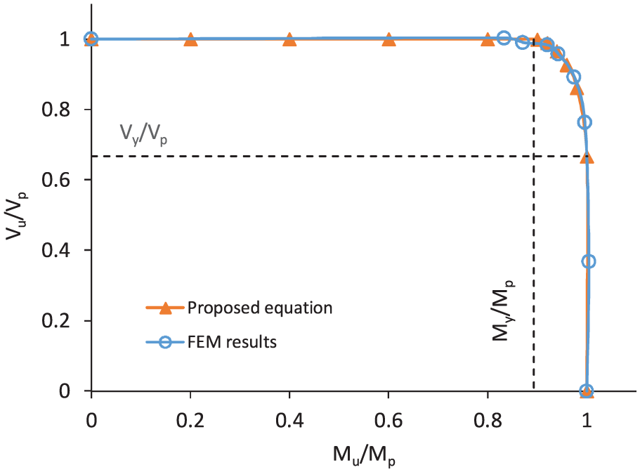
Comparison of proposed M-V interaction relationship with FE results.
The effect of stiffeners on M-V interaction relationship was also investigated with analyzing all EBF samples with and without stiffeners. Comparing the results shows that the effect of stiffeners is about 3% for shorter links and it tends to zero for the links of length greater than 1.7 m. Therefore, the effect of stiffeners on the capacity of highly ductile members can be neglected.
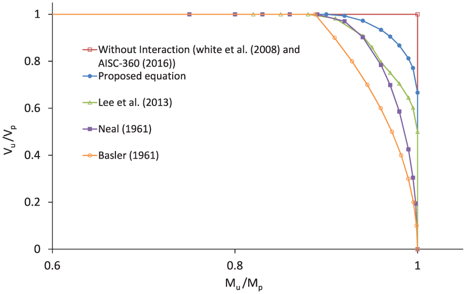
Comparison with existing relationships
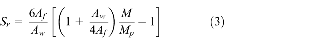
Table 3 lists three M-V interaction relationships available in the literature. Neal (1961b) presented a lower bound solution for considering M-V interaction in I-sections represented in Table 3. Basler’s relationship assumes that when the web is fully plastic under shear, the section still can carry moment equal to the flanges moment capacity,
Some of the existing M-V interaction relationships.

Figures 6 and 7 compare the proposed relationship with others’ for IPB300 and IPB1000 sections, respectively. As can be seen in these figures, the difference in predictions of the relationships for IPB1000 (Figure 7) is more significant than IPB300 (Figure 6). In the both figures, the proposed relationship lies between case of without interaction (Azizinamini et al., 2007; Daley et al., 2016; White et al., 2008) and others’ interaction relationships (Basler, 1961; Lee et al., 2013; Neal, 1961b). It means that the proposed relationship prediction for the shear capacity is more than those of existing interaction relationships. Those relationships are derived from the lower bound plasticity analysis by assuming a stress distribution on a beam cross section, while the proposed relationship was obtained by investigating FE results considering more realistic stress distribution based on theory of plasticity.
Comparison of the proposed relationship with others’ for IPB300.

Comparison of the proposed relationship with others’ for IPB1000.
Also, examination of the numerical results showed that the proposed relationship is more suitable for an associated plasticity model in the force space and could be used for estimating plastic rotational and plastic slip at the developed mixed plastic hinges in the frame. Although the proposed relationship is obtained based on EBFs, it can be used for any highly ductile member with I-section in steel frames and other suitable cases.
Mechanism analysis of steel frames using the proposed M-V interaction relationship
In many structural design policies, one needs to estimate the collapse load as the primary goal of design. Plastic mechanism analysis is a suitable approach, which could be used, at least, for the basic and preliminary design. For moment frames, plastic design has been developed and used since 1948 (Horne and Morris, 1981). Due to complexity of mixed hinge analysis, limited work has been introduced for practical application in design. Any M-V relationship can be used in the nonlinear step-by-step static or dynamic analysis of frames, provided to accompany a flow rule for plastic deformation.
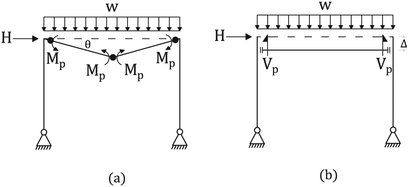
In order to show the applicability of the proposed interaction equation for plastic analysis of structures, a single-bay portal frame with pinned supports subjected to a uniform gravity load, w, and a lateral load, H, is considered. The height and span length of the frame are denoted by h and L, respectively. It is assumed that the columns are stronger than the beams and the axial load will not affect the results. In the mechanism method, the collapse load is the minimum load obtained by comparing all possible mechanisms’ loads.
Virtual work method is employed to obtain the mechanism loads. The principle of virtual work is an alternative way of expressing the equilibrium condition. In the virtual work method, a fictitious work is computed with a set of statically admissible forces assumed to remain constant while they do work on a set of infinitesimal, kinematically admissible displacements. The force and displacement distribution may be independently prescribed. The statically admissible force system is defined as one satisfying the equilibrium and force boundary conditions. A kinematically admissible displacement is one satisfying any prescribed displacement boundary conditions and to be continuous in the interior of the body (Malvern, 1969). In the mechanism analysis of a frame, the structure consists of rigid members interconnected by the plastic joints, which can transfer internal forces. The virtual work of such joint forces must be added to the work of external forces (Malvern, 1969).
In the next section, the frame is analyzed without considering the M-V interaction, and in the following section, the frame is analyzed with considering the M-V interaction.
Frame collapse loads obtained without considering M-V interaction
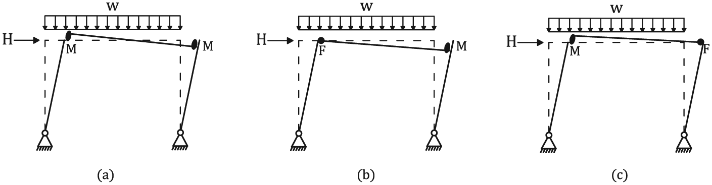
Ignoring the M-V interaction, five mechanisms are possible to occur. Two of them are beam mechanisms (Figure 8(a) and (b)), one is a story mechanism (Figure 9(a)), and two other ones are mixed mechanism (Figure 9(b) and (c)). For the mixed mechanisms, for any given uniform gravity load, w, the corresponding lateral collapse load, H, is calculated.
Possible beam mechanisms of the frame without M-V interaction consideration. (a) Mechanism 1: beam flexural (BF) mechanism and (b) mechanism 2: beam shear (BS) mechanism.
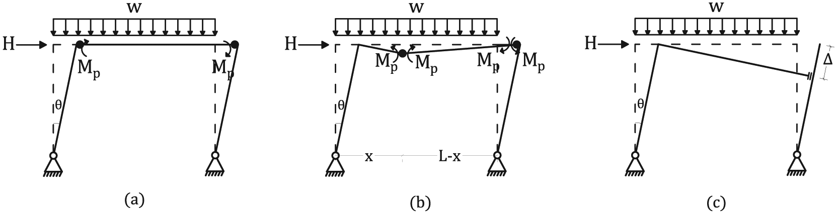
Possible story and mixed mechanisms of the portal frame, without considering M-V interaction effect. (a) Mechanism 3: story mechanism by forming two flexural plastic hinges at the beam ends (F-F); (b) Mechanism 4: mixed mechanism by forming one flexural plastic hinge at the beam’s right end, and another one somewhere along the beam span (IF-F); (c) Mechanism 5: mixed mechanism by forming just one shear plastic hinge at the beam’s right end (-S).
Figure 8(a) is a beam flexural (BF) mechanism, mechanism 1, formed by two flexural plastic hinges at beam ends and one at the middle of the beam, with the collapse load of
Figure 9(a) presents the story mechanism (mechanism 3), which is formed by two flexural plastic hinges at the beam ends with the collapse load of
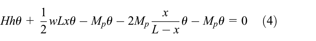
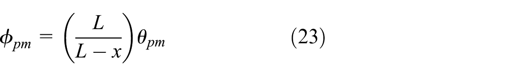
By minimizing the lateral load, H, the location of the interior hinge, x, could be determined. Also, by noting the fact that at the interior plastic hinge the shear force should be zero, the interior hinge location could be determined
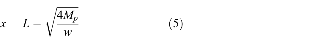
Substituting equation (5) into equation (4) results in the lateral collapse load given as a function of w

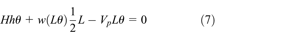
The last mechanism (mechanism 5) shown in Figure 9(c) is formed by just one shear plastic hinge at the beam end. Virtual work relationships for mechanism 5 is expressed by equation (7), which results in the lateral collapse load as a function of w (equation (8))

Hence, if the moment–shear interaction can be ignored, for the conditions that w is less than both

Frame collapse loads obtained by considering M-V interaction
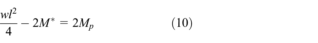
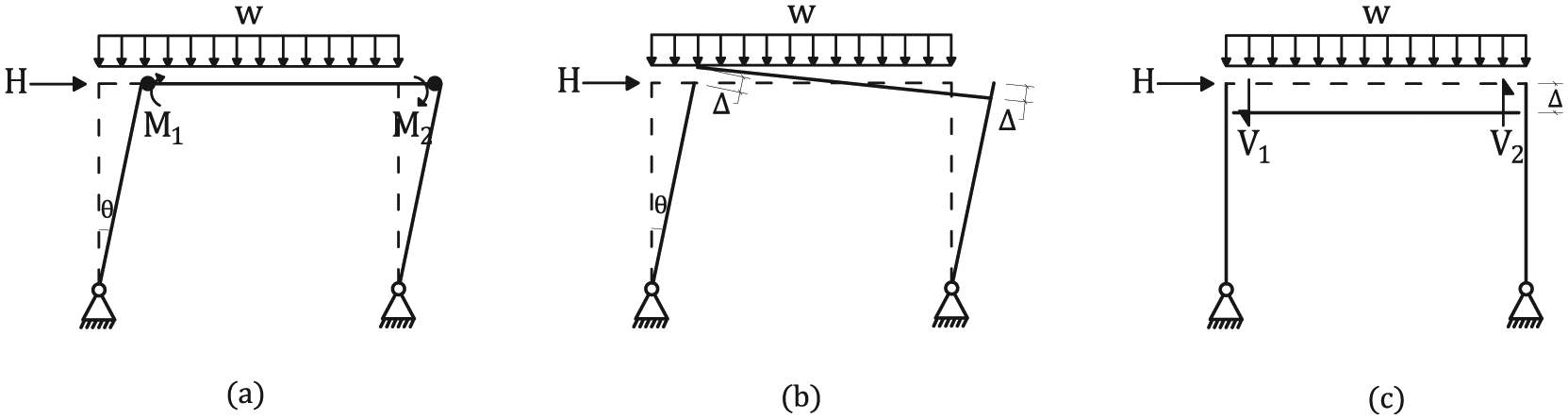
To calculate the collapse load of the portal frame incorporating M-V interaction effect, five mechanisms, mechanism 6 to mechanism 10, shall be appended to the previous investigated mechanisms. Mechanism 6 is the third beam mechanism, formed by two mixed hinges (M) at the beam ends and one flexural plastic hinge (F) at the beam center, and it is named beam mixed (BM) mechanism (Figure 10(a)).

(a) Mechanism 6: beam mixed (BM) mechanism of the frame by forming two M-V mixed hinges at the beam ends and one flexural plastic hinge at the beam center. F and M stand for flexural plastic hinge and mixed hinge, respectively. (b) and (c) are frame virtual deformations used in writing virtual work relationships for mechanism 6.
To solve mechanism 6, two equilibrium equations and the M-V interaction equation are required. As a substitute for the direct equilibrium equations, two independent virtual deformations are considered (Figure 10(b) and (c)).
For the virtual deformation of Figure 10(b), which considers only virtual rotation at the beam ends and the center, one could obtain
For the virtual deformation of Figure 10(c), which considers only vertical slip at the beam ends, it could be seen that

The third equation relates
Accordingly, the collapse gravity load,

By means of virtual work method or static equilibrium, the ultimate collapse load can be determined. However, the corresponding plastic rotation and shear plastic displacement of plastic hinges remain unknown and their determination requires incremental or stage-by-stage analysis based on assumed load path, which are out of the scope of this article.
By forming just two hinges at the beam ends, there are three possible mixed mechanisms (mechanisms 7 to 9), which include interaction of gravity and lateral loads. In mechanism 7, Figure 11(a), both hinges are mixed hinges, M, while in mechanisms 8 and 9, Figure 11(b) and (c), there is one flexural plastic hinge, F, and one mixed hinge.
Possible mixed mechanisms of the portal frame, considering M-V interaction effect. F and M stand for flexural plastic hinge and mixed hinge, respectively. (a) Mechanism 7 (M-M), (b) mechanism 8 (F-M), and (c) mechanism 9 (M-F).
Regarding the mechanism 7, there are five unknowns,
(a)–(c) Portal frame virtual deformations used in writing virtual work relationships.
For the virtual deformation of Figure 12(a), which only contains virtual rotations at the beam ends, one could obtain

In Figure 12(b), to simplify the virtual work equation, only anti-symmetric vertical slips are considered at the beam ends. In this way, the gravity load does not do any work, and

In the third virtual deformation, Figure 12(c), the same vertical slips are considered at the beam ends, to prevent the appearance of lateral load in the virtual work equation, so results in

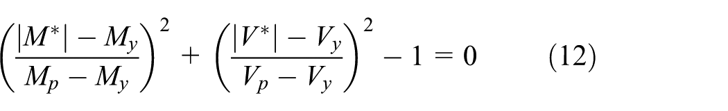
Two equations can be obtained from yield surface of equation (2) as follows

The lateral collapse load of mechanism 7 can be obtained by solving simultaneously equations (14) to (18), which contains two nonlinear equations of (15) and (16). These set of equations were solved using MATLAB software (MathWorks, Inc., 2014).
Similar to mechanism 7, the lateral collapse load of mechanism 8 is calculated by setting
Finally, the last possible mechanism, mechanism 10, consists of one mixed hinge at the beam right end and one flexural plastic hinge along the beam (Figure 13(a)). To obtain lateral collapse load of mechanism 10, the


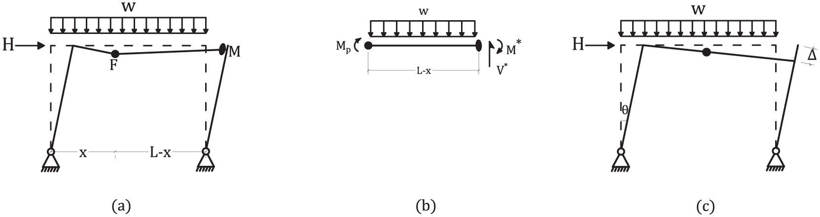
Mechanism 10 (IF-M): forming by two hinges consists of one mixed hinge at the beam right end and one flexural plastic hinge along the beam. (b) Free body diagram of the part of the beam between flexural and mixed hinges. (c) Frame virtual deformations used in writing virtual work relationship.
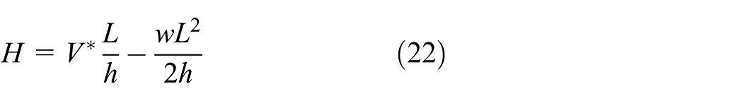
The only remaining unknown, which is the lateral collapse load could be calculated using the virtual work equation based on the chosen virtual deformation shown in Figure 13(c), where
Numerical examples
To study the dependency of the portal frame capacity on the moment–shear interaction, some numerical examples are presented. For this purpose, three portal frames with height 3 m and span lengths 6, 9, and 11 m are considered. The beam section of all frames is IPB1000, so the beam span to depth ratios,
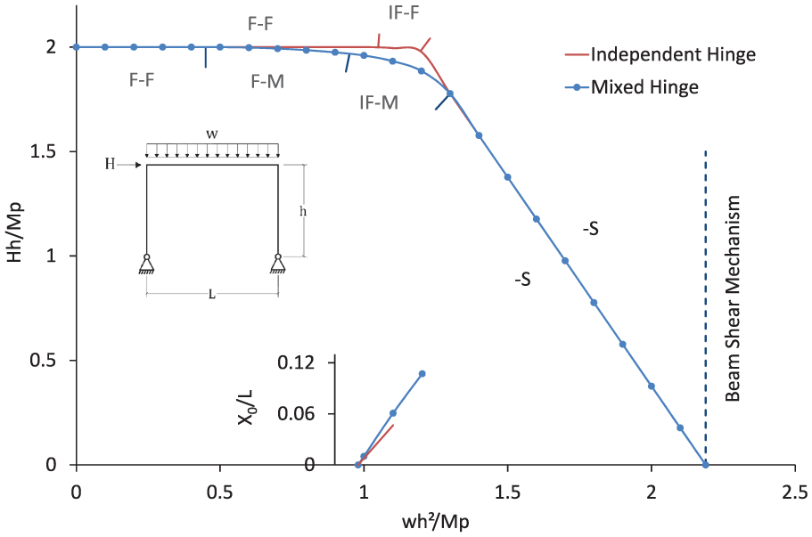
Frame capacity for a portal frame with h = 3 m, L = 6 m, and beam section of IPB1000 (L/d = 6).

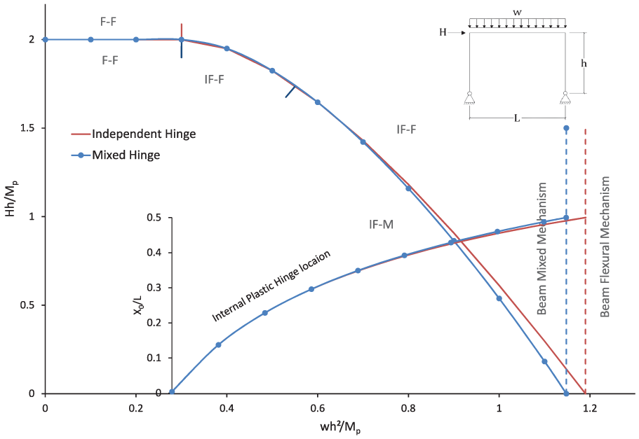
Frame capacity for a portal frame with h = 3 m, L = 9 m, and beam section of IPB1000 (L/d = 9).
Frame capacity for a portal frame with h = 3 m, L = 11 m, and beam section of IPB1000 (L/d = 11).
Each figure contains two curves with and without M-V interaction effect. As depicted in Figures 14 to 16, the capacity curve including M-V interaction effect (mixed hinge) lies below the one in which the interaction effect is neglected. The maximum differences are about 5% in Figure 14, 13% in Figure 15, and 63% in Figure 16. Each figure contains additional diagram showing the relative location of interior plastic hinge along the beam
For the frame with shorter span, as can be seen in Figure 14, the curve “independent hinge” contains three regions. When w is less than
Figures 15 and 16 show that despite the larger value of the beam span to depth ratio,
For the frame with the larger span, Figure 16, beam mechanism occurs by forming mixed hinges (mechanism 6), while using independent hinge assumption, flexural plastic hinges form the beam mechanism (mechanism 1). As can be seen in this figure, considering M-V interaction results in 3.5% decrease in the frame gravity load capacity.
To investigate the effect of span to depth ratio of the beam
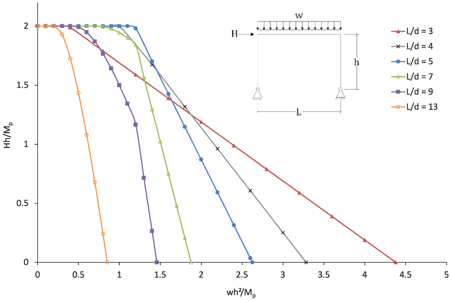
Frame capacity ignoring M-V interaction effect for a portal frame with h = 3 m, beam section of IPB1000, and different span to depth ratio of the beam.
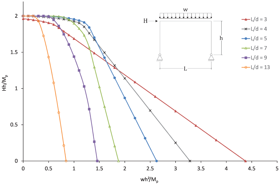
Frame capacity considering M-V interaction effect for a portal frame with h = 3 m, beam section of IPB1000, and different span to depth ratio of the beam.
Post-mechanism deformation at plastic hinges
To ensure satisfactory behavior of a structure in a severe earthquake, the inelastic deformation in the plastic hinges should not exceed their inelastic deformation capacity. Hence, it would be useful to relate the plastic hinge deformation to the plastic story drift angle. For the strong ground motion, the design or expected drift angle depends on the intensity of earthquake, and it can be estimated using seismic design codes (ASCE 41-17; ASCE 7-16). The inelastic capacity of plastic hinges could be obtained from test results and also estimated using existing codes (ASCE 41-17). Pre-mechanism deformations in the inelastic hinges depend on the load path and require incremental analysis. However, the post-mechanism deformation of plastic hinges could be estimated by satisfying kinematic compatibility requirements and normality condition as a flow rule. In the case of just flexural hinges or just shear hinges, the flow rule will be one-dimensional and practically post-mechanism deformation of plastic hinges could be estimated just by satisfying kinematic compatibility requirements. However, in case of existence of mixed hinges, it is necessary to consider the relation of the plastic hinge rotation and shear deflection of any mixed hinges using a flow rule. In this section, for the single-bay portal frame defined previously, simplified relations are derived to estimate the post-mechanism deformation of plastic hinges for a prescribed lateral drift. For sake of brevity, just two mechanisms are presented (mechanisms 4 and 10).
Since mechanism 4 forms by two flexural hinges with equal rotations, and there is not any mixed hinges, so the post-mechanism plastic rotation of both hinges,
where
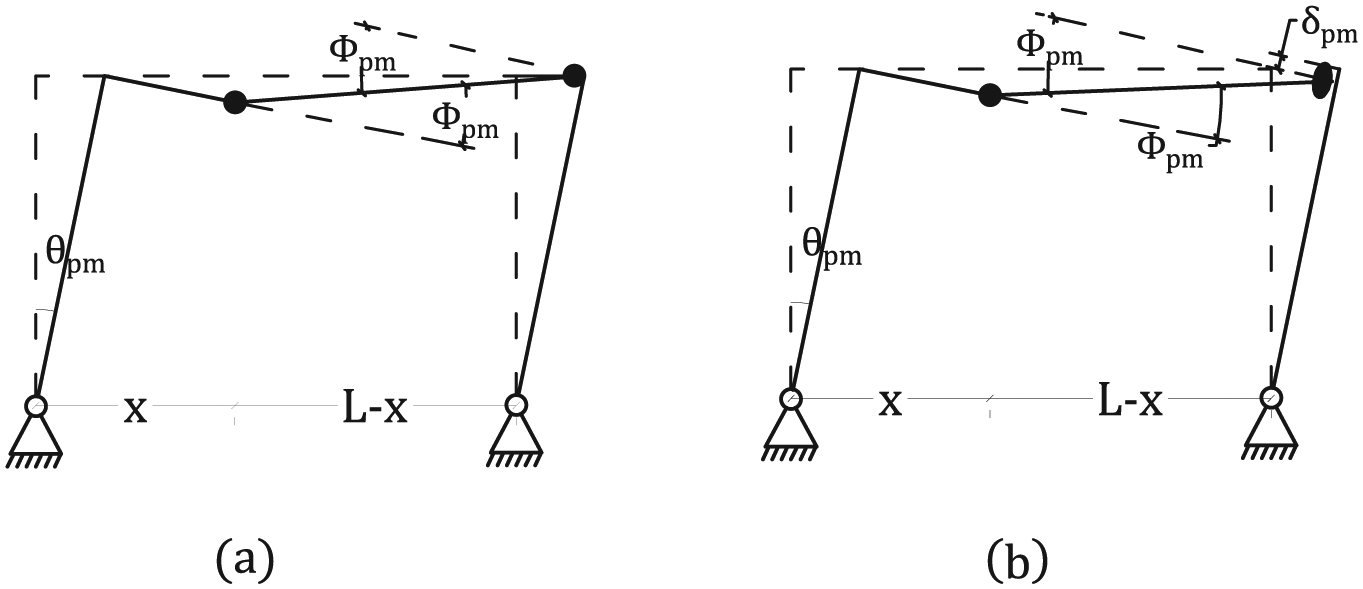
Plastic hinges deformations in (a) mechanism 4 (IF-F) and (b) mechanism 10 (IF-M).
Regarding mechanism 10, kinematic compatibility requirements result in
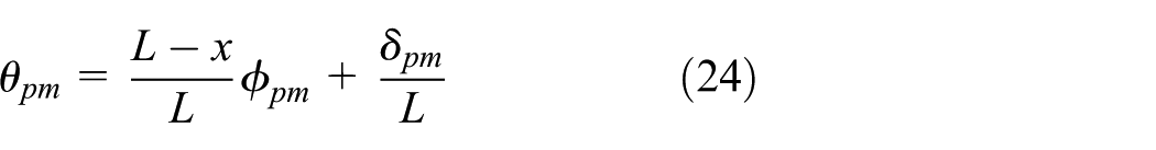
where
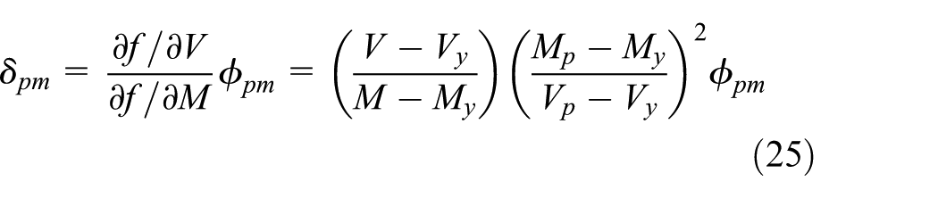
Now, substituting equation (25) in equation (24) results in
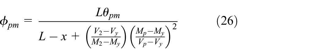
where
As a numerical representation, the portal frame with beam length of 9 m, which its capacity curve presented in Figure 15, is considered. The normalized plastic rotation,
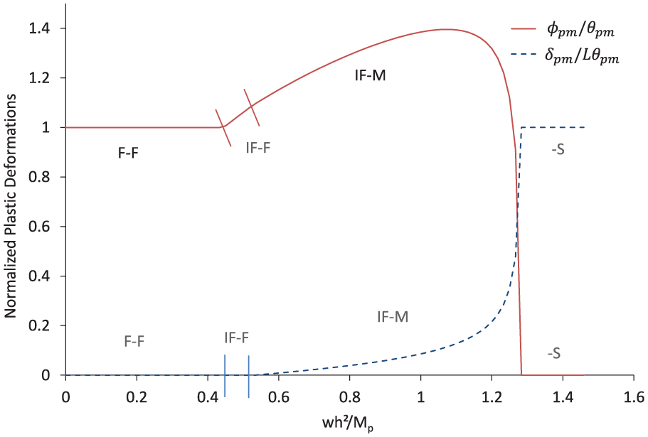
Normalized plastic deformations at the hinge at the right end of the beam for the frame with beam of length 9 m.
Conclusion
Plastic analysis of frames and EBFs with intermediate link length is governed by the combination of flexural and shear yielding. In the current work, a simple and design-oriented relationship was developed and proposed to account the moment–shear (M-V) interaction of highly ductile steel I-sections within the framework of plastic design. Furthermore, using the proposed relationship, a mechanism analysis was carried out on a one-bay portal frame considering all possible collapse mechanisms. A simplified approach was developed to solve a set of nonlinear equations for the collapse mechanisms, considering M-V interaction. Considering mixed hinges adds five more mechanisms to the primary mechanisms based on the independent flexural and shear plastic hinges. The effect of gravity load and possibility of forming plastic hinges along the beams are considered and their exact locations are determined. To investigate the dependency of the portal frame capacity on the moment–shear interaction, numerical examples were solved. The obtained results indicate that, in general, the effect of M-V interaction on the capacity of frames cannot be ignored. Finally, by satisfying kinematic compatibility requirements and normality condition, post-mechanism deformations at plastic hinges were obtained for a prescribed lateral drift ratio.
Footnotes
Declaration of Conflicting Interests
The author(s) declared no potential conflicts of interest with respect to the research, authorship, and/or publication of this article.
Funding
The author(s) received no financial support for the research, authorship, and/or publication of this article.