
Abstract
Since geogrid is a new and under-researched material in terms of reinforced concrete members, this study focuses on the experimental validation of the feasibility of this material to be used instead of steel rebars. Despite the apparent mechanical disadvantages of geogrid, higher durability and special applicability in harsh environments are significant advantages of the material. A total of 18 deep beams as nine unique models with various web-openings have been tested in this study. Each one of the conjugate test samples was designed conventionally by steel reinforcements, while the other one was designed by hybridizing geogrid and steel as the web reinforcement. Comparison of the structural performance and applicability of geogrid, which is used as the web reinforcement instead of steel, in terms of the flexural and mostly the shear strength of concrete members, is the main goal of the research. Because of the complexity depending on their geometrical irregularities, deep beams with web-openings were experimentally investigated for the validation of the feasible use of geogrid material. Experimental comparison of the deep beams, which have been subjected to flexural testing, revealed that geogrid has a remarkable contribution to the structural performance of reinforced concrete members. Alongside the advantage of geogrid’s structural flexibility and especially the bonding performance, higher ductility and stiffness levels of hybrid beams highlight the eligibility of geogrid to be used instead of steel rebars in reinforced concrete structures.
Introduction
Reinforced concrete (RC) deep beams are important structural members with various applications. Over the years, RC deep beams have been of increasing use in structural engineering (Hu and Tan, 2007) and they have substantial applications ranging from pile caps, shear walls, offshore structures, foundations, to transfer girders between two sections of a tall building. The design process of the RC structures requires some critical decisions such as dimensions of the structural members, material properties, and detailing of rebars to be done by the designer, owing to the application necessity of the members (Bekdaş and Temür, 2017). Based on the general acceptancy in the literature, flexural members with clear span to overall depth ratios less than 2 shall be designed as deep beams, taking into account non-linear distribution of strain, lateral buckling, and the increased anchorage requirements in such members. Throughout these structural members, a significant amount of the load is carried to the supports by fictitious compression struts between the loading and reaction points. Some experimental results and analytical reports have indicated that shear strength, redistribution of internal forces before failure, and internal force mechanisms in deep beams are quite different from those in slender beams (Yang et al., 2006). Considering also that a/d ratio (shear span/effective depth) is too small, arch action gets more dominant than beam action. Hence, it is not appropriate to consider linear stress distribution obtained from Bernoulli hypothesis (Celep and Kumbasar, 2005). Location of the loading (top or bottom face) and load type (single or distributed) have great significance as well as the anchorage necessity of the rebars (Ersoy and Özcebe, 2001). The elementary theory of bending for simple beams may not be applicable to deep beams even under the linear elastic assumption. A deep beam is in fact a vertical plate subjected to loading in its own plane. The strain or stress distribution across the depth is no longer a straight line, and the variation is mainly dependent on the aspect ratio of the beam. The analysis of a deep beam should therefore be treated as a two-dimensional plane stress problem, and two-dimensional stress analysis methods should be used in order to obtain a realistic stress distribution in deep beams even for a linear elastic solution (Kong, 2002; Özkal, 2017).
In various forms of constructions, openings in the web region of deep beams are sometimes provided for essential services and accessibility. In such situations, it is highly important to know the behavior and ultimate strength of these beams (Kong, 2002). While the internal state of stress in B-regions is easily derived from the sectional forces (Schlaich et al., 1987), openings can cause the formation of D-regions and thus significant changes in the distribution of forces (ACI 318M-14, 2014). Hence, stress concentrations at openings should be taken into account in the detailing of reinforcement (Eurocode 2, 2004), as well as the notable contribution of principal tensile reinforcement, particularly the web reinforcement, controls crack widths and deflection of deep beams. Inclined form of web reinforcement, which is placed perpendicular to the plane of rupture (critical diagonal crack), has been found to be the most effective arrangement to offer resistance to sliding. The next practical and effective type is the horizontal web steel which with nominal vertical web steel may further increase the effectiveness of the beam and so its strength. Failure will be gradual and slow in beams with web reinforcement, while it is sudden in beams without web reinforcement (Kong, 2002).
Geogrids are manufactured from the polymers such as polyester, polypropylene, polyethylene, and polyvinyl in different production forms (uni-axial, bi-axial, and tri-axial). Alongside having an acceptable tensile strength, their significant attributes could be summarized as follows: resistance to chemicals, resistance to corrosion, resistance to temperature variation, not being attacked by microorganisms because of having no nutritional values, and inertness to aqueous solutions of acids, alkalis, and salts. Difficulty of steel reinforcement layout with respect to cross-sectional dimensions and requirement of substantial construction work as well as corrosion risk has revealed the necessity of geogrid use in some of the engineering structures. Especially, the adverse effects of corrosion such as the reduction in reinforcing bar cross-sectional area and bond slip should not be neglected throughout structural construction. However, application of geogrids as reinforcement material in concrete has not attracted notable notice yet.
The first use of geogrids as interlayer products dates back to the early 1980s. Stiff, punched and drawn, polypropylene, bi-axial geogrids developed in the United Kingdom were tested extensively at various sites and at the University of Nottingham (Brown et al., 1985; Penman and Hook, 2008). Geogrid studies up to now have generally been focused on geotechnical engineering mostly as a soil stabilizing material. In brief, geogrid reinforcement has been known to be an effective method to enhance the performance and service life of different earth structures such as embankments, pavements, foundations, and retaining walls (Hussein and Meguid, 2016). Load-bearing capacity of the soil is increased by placing a layer of geogrid at the interface of the clay subsoil and the compacted granular fill (Demir et al., 2014). Hence, the settlement performance of shallow foundations is improved by the efficient application of geogrid. Further research on using geogrids as an interlayer material related to asphalt and pavement problems has been made but not in a wide range. The use of geogrid reinforcement of base course layers offers one such alternative. Geogrid use as the base reinforcement has a capability of extending the service life of the pavement or reducing the base thickness (Abu-Farsakh et al., 2014; Berg et al., 2000). Rather than being a woven or knitted geotextile, geogrids are plastics formed into a grid-like configuration. The marked characteristic of all geogrids is apertures, which are the openings between the adjacent transverse and longitudinal ribs. The aperture should be large enough to allow interlocking with surrounding soil, rock, earth, and other geotechnical materials for soil stabilization (Zheng et al., 2016). Inversely, this aperture structure does not fit to the application purpose of this material for reinforcing concrete structural members. Following the increase in number and quality of geogrid-focused studies, manufacturers would consider producing proper shapes and enhancing mechanical properties.
To fill the gap of geogrid studies to be used as reinforcing material in flexural concrete members, research works of Tang et al. (2008), El Meski and Chehab (2014), and Chidambaram and Agarwal (2014, 2015, 2016) could be placed on the starting point. These experimental studies reveal that geogrid use in concrete sections provides high load-bearing capacity and ductility compared with the plain concrete sections. However, its preliminary and essential application purpose up to the present has been to build capital roads to the weak bases of platforms, to strengthen slopes and cones of roads, to create retaining walls, to expand existing roads, and to equip water currents with crimping pipes (Khmelev et al., 2007).
This study focuses on the applicability of geogrid material in RC structural members and experimental investigation of hybrid-reinforced deep beams with web-openings, which are uncommon and irregular members in the construction practice and have complex detailing characteristics. This type of RC members has been selected in order to investigate the shear behavior of geogrid material in RC structural members. In addition to the conventionally designed beams, conjugates of those were designed by placing geogrid as the web reinforcement. Through the record of deflection values from five points, deflection and energy dissipation capacity of the test samples were examined and compared within the couples. Although geogrid is generally preferred for geotechnical applications, it is a new material in terms of structural members. However, flexibility and bonding advantage of geogrid exhibit the feasibility of this material to be used in RC easily. In compliance with the experimental results, geogrid was found to be effective when it is used as a reinforcement material. This study has significance with respect to the applicability and advantages of geogrid reinforcement in RC structural systems, especially in which shear behavior is a prior concern.
Experimental setup and materials
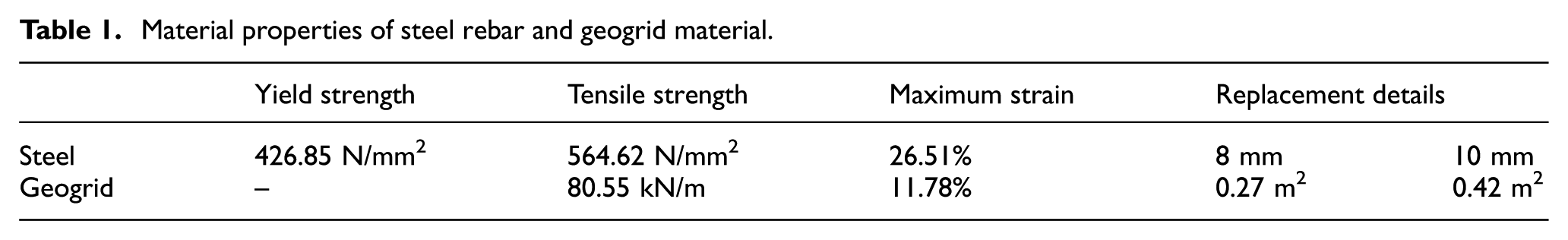
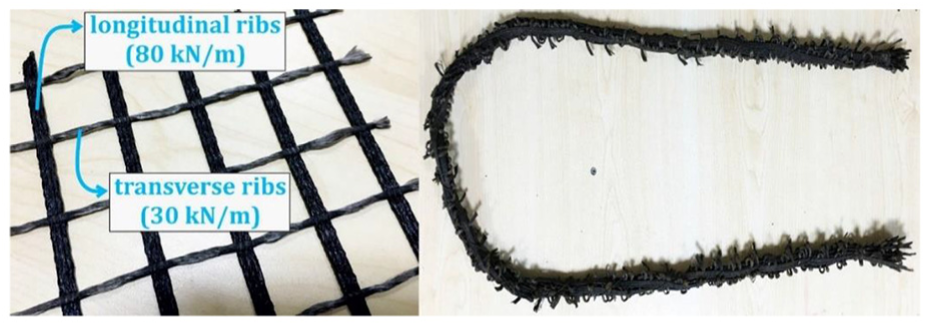
Ready-mixed concrete, which has a slump of 200 mm and cylinder compressive strength of 25 MPa, was used and concrete casting was performed together for all of the deep beams. Reinforcement bars were established from S420 construction steels. Referring to the manufacturer’s identification sheet, aperture size is 27 mm × 27 mm, tensile strength is 80 kN/m, and maximum unit strain is 12% for the geogrid material that was used in this study. Tensile strength tests (Figure 1(a) and (b)) of geogrid were performed in the laboratory and the strength–unit strain relationship has been found close to the manufacturer’s information. Tensile strength tests of geogrid have been performed depending on GG4(b) (2012), ASTM D4595-11 (2011), and ASTM D6637/D6637M-15 (2015) recommendations. Results of three specimens for each testing methods (wide-width strip method and multi-rib tensile method) were evaluated and it has been found that multi-rib tensile method reflected more reliable material characteristics (Figure 2). Although this material does not have a notable yield point, its tensile strength and maximum strain values are acceptably high against the low stiffness with respect to the steel. Geogrid steel replacement was calculated and applied by assuming that the steel’s design tensile strength is the yield strength while that of geogrid is the rupture strength. For instance, 0.27 m2 geogrid is required in place of a meter of 8-mm steel rebar (Table 1).

Tensile strength test setups of geogrid material: (a) wide-width strip method and (b) multi-rib tensile method.

Tensile strength test graph of steel rebar and geogrid material.
Material properties of steel rebar and geogrid material.
Deep beams were subjected to a single point loading at the top-middle of the beams. A monotonic loading program was applied considering the load values. Two hydraulic cylinders and load cells, which have 1200 kN total capacity, were used simultaneously. It was regarded that the displacement value of the beams’ middle-bottom point would be adequate because of the various web-opening positions in the test models. Hence, deflection of the test samples was measured using five displacement transducers by placing them at equal distances under the beams. Rigid loading frame and testing platform in Erzincan University Structural Mechanics Laboratory can be seen in Figure 3. Load and deflection values were recorded by a data acquisition system in order to obtain structural performance information from the test samples.
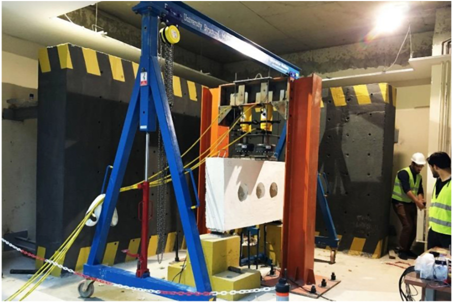
Rigid loading frame and testing platform.
Design of the test samples
Nine unique models as couples (a total of 18 deep beam samples) were designed and tested for the experimental part of this study. All beams have a length of 1750 mm and height of 900 mm with a 300 mm width. Loading and support details as well as model dimensions are shown in Figure 4. In the figure, minimum requirements for the reinforcement layout of a deep beam without any web-openings have also been demonstrated. Various types of web-openings were placed in the deep beams at various positions. Dimensions are 650 mm × 250 mm for rectangle openings, 250 mm × 250 mm for square openings, and 250 mm diameter for circle openings. Conjugate test samples were designed for each models, with steel and hybrid (steel and geogrid) reinforcement. While the first sample was produced totally with steel reinforcements, second one was produced mostly with geogrid as the web reinforcement. On the other hand, reinforcement layout pattern was considered identical for each of the models except the adjacencies of web-openings.
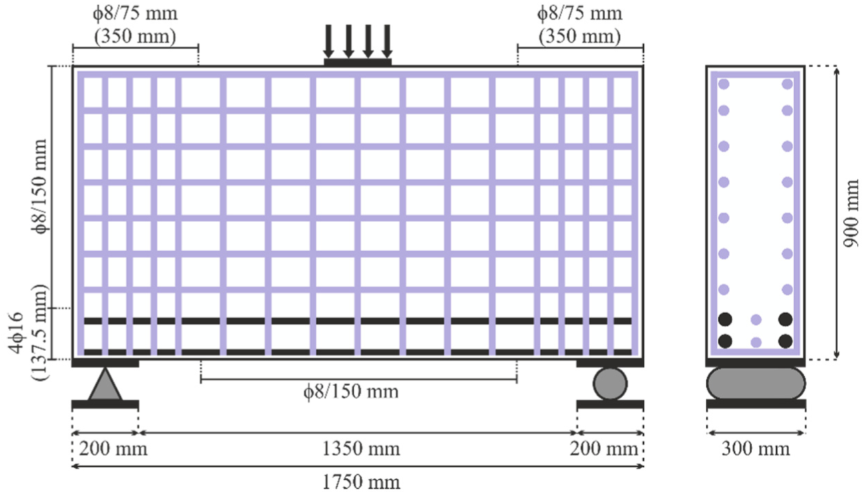
Loading and support details of test models.
All theoretical calculations for the reinforcement layout design of deep beams were performed using the instructions of national code TS 500 (2000), which is essentially compatible with Eurocode 2 (2004) and ACI 318M-14 (2014), but setting any material resistance factors equal to one. Considering that clear span ln = 1350 mm, web width bw =300 mm, effective depth d = 870 mm, design compressive strength of concrete fcd = 25 MPa, and design axial tensile strength of concrete fctd = 1.8 MPa, the first crack shear capacity of the cross section (Vcr) is calculated from equation (1) as 305.37 kN. Regarding this result, load value for the deep beams is defined as 600 kN in order to attain design shear force Vd = 300 kN. Since ln/d < 2.0, Vd should satisfy equation (2), being less than 1305 kN, to abstain from the necessity of increasing beam’s cross-sectional dimensions


Lever arm of internal forces and cross-sectional area of principal tensile reinforcement are calculated as z = 710 mm and As =779.68 mm2 from equations (3) and (4) taking overall span length l = 1750 mm, overall depth h = 900 mm, design value of bending moment Md = 232.5 kN/m, and design yield strength of reinforcement fyd = 420 MPa. As is selected as 4 mm × 16 mm rebar (804.25 mm2) and distributed to a lane with height of 137.5 mm (l/h ⩾ 1 ⇒ 0.25 h − 0.05l).


Simplified equations (5) and (6) are used for the calculation of web reinforcement. In these equations, Av and Avh are cross-sectional area of vertical and horizontal web reinforcement, while s and sh are spacing values of those, respectively. Accordingly, Av and Avh are selected as 8-mm rebar with 150-mm spacing


Because internal force transfer becomes intensified at the support regions, web reinforcement spacing is reduced by half for vertical and horizontal rebars. Additional horizontal rebars at the support regions are placed in a lane with a width of 0.3l (525 mm) and the same height of As (137.5 mm). Additional vertical rebars are placed in a lane with a width of 0.2l (350 mm) and height of 0.5l (875 mm). These calculations have been used to determine the minimum requirements of a deep beam without any web-openings, as shown in Figure 4.
It is known that first cracks in RC deep beams with web-openings are expected to occur between supports, openings, and loading point. Hence, diagonal steel bars were placed perpendicularly to the fictitious internal struts with the aim of retarding these cracks in order to ensure that deep beam samples do not present rapid failure. Another and main purpose of these diagonal steel bars is to converge the structural performance of different models into a reference value as much as possible by lessening stress concentration effect near the openings. It is important to state that these diagonal bars and longitudinal/transverse web reinforcements, which are next to the web-openings and at the outer regions of the beams, were preferred as steel for all the beams for the assembling purpose. In addition, principal tensile reinforcements were not replaced by geogrid material because of the requirement of high reinforcement ratio and the objective of the study to investigate shear behavior of geogrid.
Reinforcement layouts of the beam models are demonstrated in Figure 5 for hybrid deep beams. The abovementioned rebar calculations have been considered as the initial pattern and adjusted into the internal geometry of the beams by considering opening locations. Principal tensile reinforcements as two lines at the bottom of the beams were selected as 16 mm, while the vertical and horizontal web reinforcements were selected as 8 mm S420 steel. Furthermore, web reinforcements next to the web-openings were selected as 10 or 12 mm, while reinforcements were placed with a less spacing near the support regions to prevent support crushing according to the above calculations and locations of the web-openings. Orange- and magenta-colored lines represent geogrid reinforcement in hybrid test samples, while purple-, cyan-, blue-, and black-colored lines represent steel rebar.
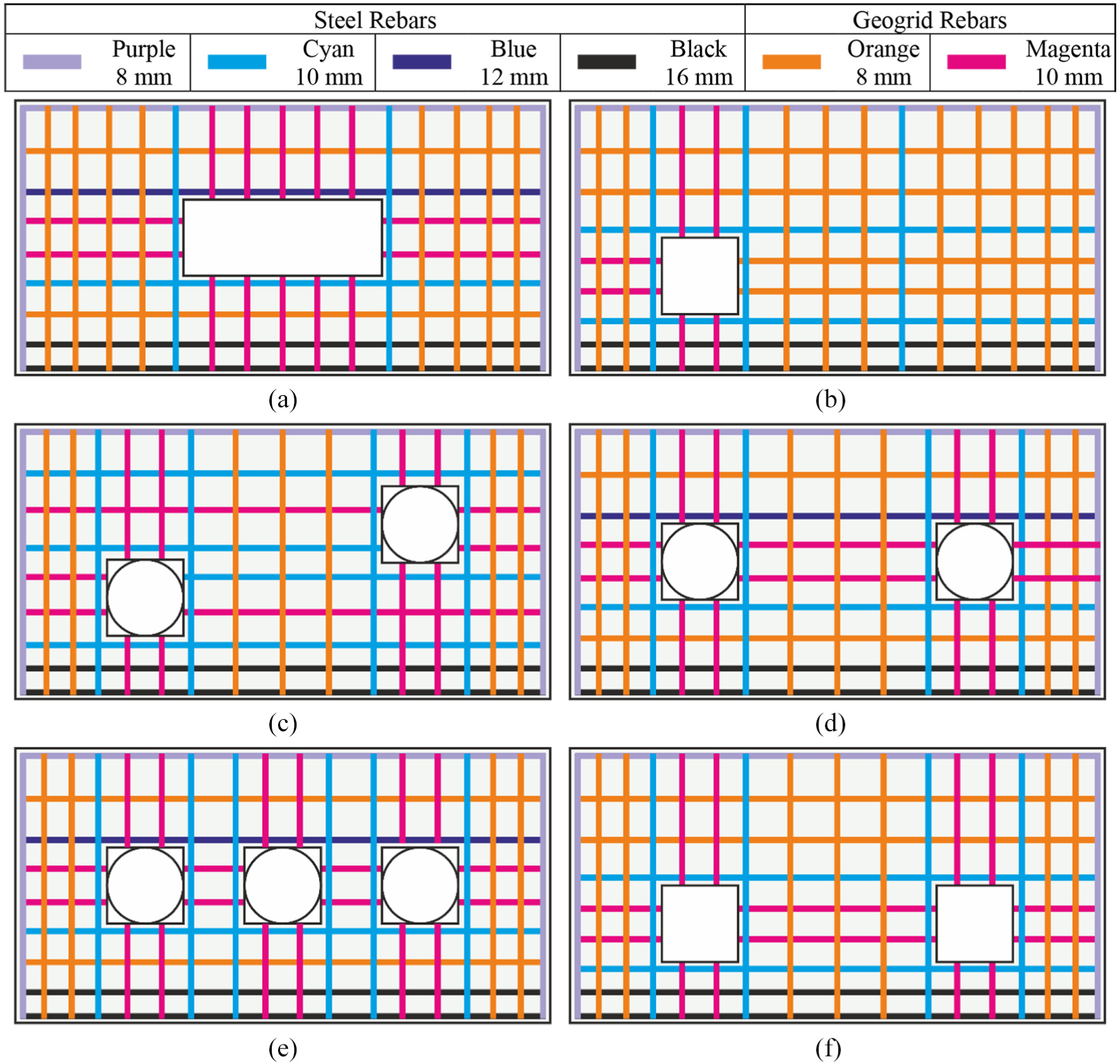
Reinforcement layout patterns of test samples: (a) Model-1, (b) Model-2, (c) Model-3 & Model-4, (d) Model-5 & Model-6, (e) Model-7 & Model-8 and (f) Model-9.
Geogrid reinforcements were prepared by rolling the strips, then fastening that rounded form via binding wire (Figure 6). This application procedure was preferred because geogrid reinforcements would probably be manufactured in rolled form in case this material is widely used in the construction industry. In addition, it has another importance to stretch all of the geogrid strips equally. Although the geogrid used in this study might be classified as a bi-axial type, it has a uni-axial behavior as reinforcement material with respect to the application style. The transverse ribs will have a passive resistance under pullout conditions, while longitudinal ribs are responsible for tensile resistance (Sieira et al., 2009). Afterward, they were tied to the existing steel reinforcements and enclosed along the outer steel bars to provide also an effective confinement. Examples of steel- and hybrid-reinforced deep beams are shown in Figure 7.
Initial and rolled form of geogrid.

Formwork and reinforcements of steel- and hybrid-reinforced deep beams.
Experimental results and comparison
Deep beams reinforced totally with steel are called Si, while the hybrid beams that consist of steel and geogrid are called Gi. Using the load and deflection values, experimental results and related schematic illustrations are presented in this section. Test samples were loaded until they cannot bear anymore or a notable drop occurred at the load value. Furthermore, loading was not stopped yet after the assumed ultimate load in order to see the failure mechanism of beams clearly. Photographs of the deep beams, which were taken after the testing, are presented in Figure 8, and initial micro-cracks are pointed with blue-dotted ellipses. Especially, the crack propagation on the collapsed beams evinces the structural behavior of the test samples. Although all of the failure mechanisms are originated from shear stresses, flexural effects were observed denser on some of the beams. Apart from this, subsequent to the failure, support crushing took place on some of the beams, on which web-openings are close to the support regions, especially S3 beam.

Photographs of tested deep beams: (a) S1, (b) G1, (c) S2, (d) G2, (e) S3, (f) G3, (g) S4, (h) G4, (i) S5, (j) G5, (k) S6, (l) G6, (m) S7, (n) G7, (o) S8, (p) G8, (q) S9, and (r) G9.
Regarding the geometric properties of deep beams with web-openings, all of the test samples exhibited shear failure as expected. Initially, it is important to state that openings have reduced the volumes of the test samples, thereby leading to smaller values than design shear capacity. Shape and position of web-openings highly affected the structural behavior of test models, while steel- and hybrid-reinforced samples of each model act less divergent depending on their similar crack patterns and measurement results. Similar curve characteristics of the conjugate test samples can be seen in the load–deflection graphs shown in Figure 9.

Load–deflection graphs of tested deep beams: (a) Model-1, (b) Model-2, (c) Model-3, (d) Model-4, (e) Model-5, (f) Model-6, (g) Model-7, (h) Model-8, and (i) Model-9.
Based on the load–deflection relationship, some numerical calculations were implemented in order to perform a parametric comparison on the behavior of test samples. Energy dissipation capacity, coefficient of ductility, initial stiffness, and maximum stiffness values are presented in Figures 10 to 13, respectively. Subsequently, all of the performance characteristics are summarized throughout a comparison of hybrid beams with conventional beams in Table 2, by representing the variation in percentages.

Energy dissipation capacity of test samples.
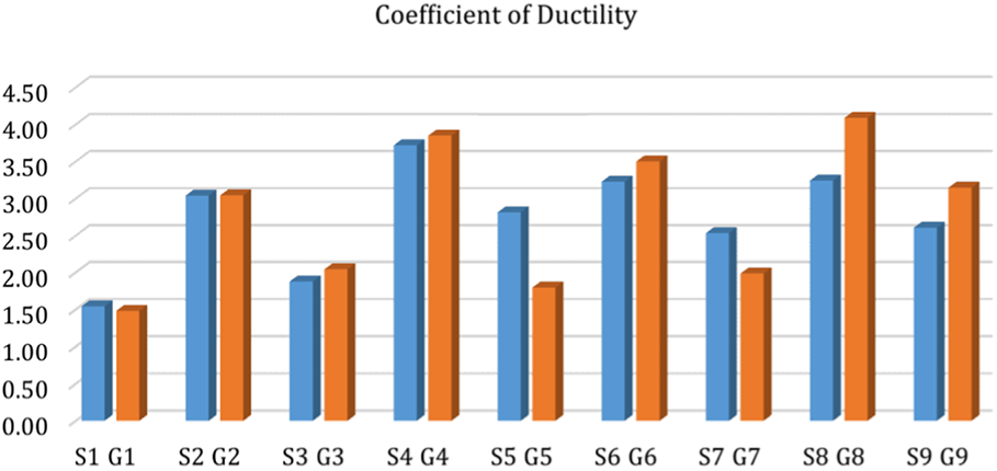
Coefficient of ductility of test samples.
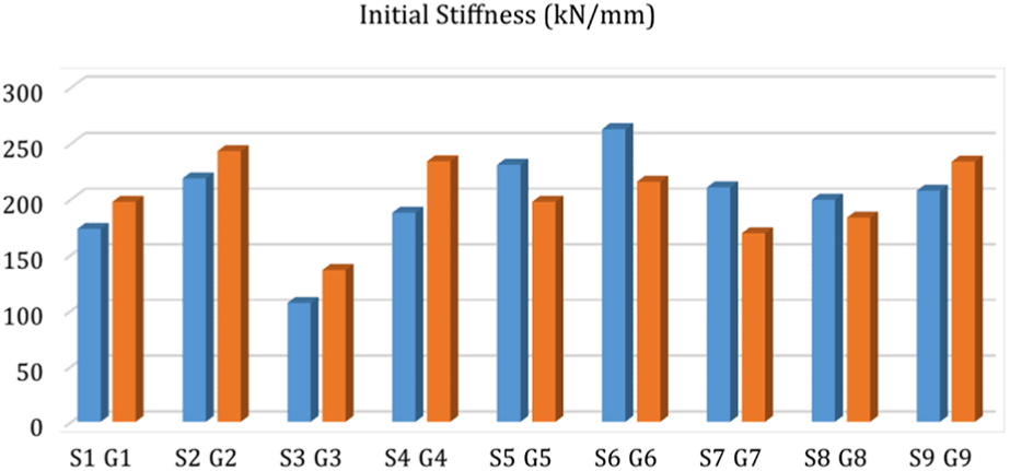
Initial stiffness of test samples.
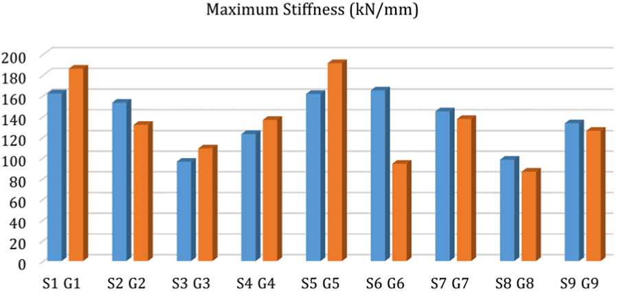
Maximum stiffness of test samples.
Comparison of the performance characteristics of conventional and hybrid beams (%).
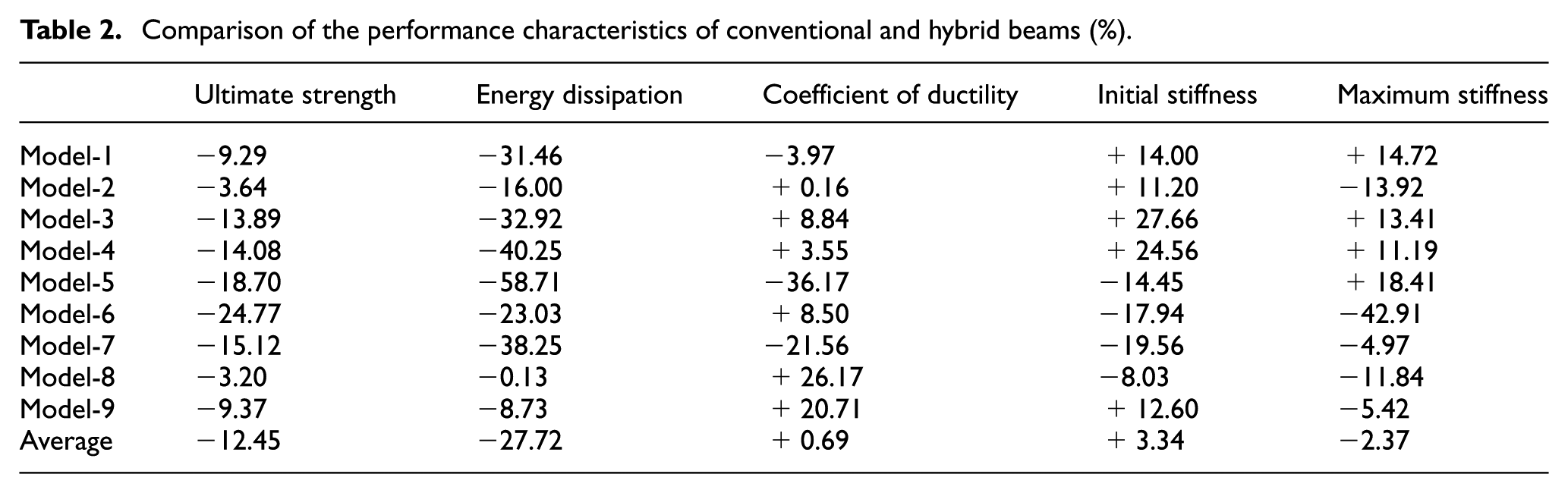
Regarding that strength and strain characteristics of geogrid are lower than steel, ultimate strength and energy dissipation values of hybrid beams are expected to be lower, as well. Nevertheless, correlation of those values are adequately close to each other despite the disadvantage of geogrid’s stiffness characteristic and advantage of steel’s hardening characteristic after yielding. On average, hybrid beams presented 87.55% ultimate strength and 62.28% energy dissipation capacity with respect to conventional beams. For all of the steel-reinforced beams, initial micro-cracks were observed, while shear force is between 150 and 175 kN. This range is 125–150 kN for hybrid-reinforced beams. However, critical cracks, which led to the failure of the beams, occurred when the load value achieved almost 75%–80% of the ultimate strength and almost the same failure modes were encountered for all of the test samples. Highest energy dissipation was obtained for S4 beam, which might be considered out of the common. Besides the positive effect of web-openings’ position and circular geometry, it is also possible that measurement faults regarding the displacement transducers yielded this excessive result. Even if not the smallest value, G5 beam’s capacity value is lower than expected. This value could have been a little higher in consideration of S5’s behavior.
Coefficient of ductility is calculated by the proportion of the deflection value at the collapse state to the deflection value at the yield state (Δ u /Δ y ). This coefficient is a significant indicator for the ductility of the structural members alongside the energy dissipation capacity. It is important to ensure that in the extreme event of a structure being loaded to failure, it will not fail in a brittle fashion without warning but will be capable of large deformations at near-maximum load-carrying capacity. This behavior is defined as ductility and it should be considered as significant alongside the strength and serviceability (Park and Paulay, 1975). Determination of yield and collapse points is highly important for the calculation of ductility and various methods have been developed for this purpose (Park and Paulay, 1975; Paulay, 1997, 1998; Priestley, 1997). One of the commonly held approaches is to assume that the RC member presents plastic behavior following a specific ratio of the nominal strength is achieved. Although a precise ratio cannot be suggested, related research works have revealed that yield strength could be assumed between 70% and 80% of the nominal strength (Paulay and Priestley, 1992; Priestley, 1997; Yüksel and Polat, 2005).
A similar approach is acceptable regarding the collapse state of an RC member. While the Comité Euro-International Du Beton (CEB, 1996) introduces ultimate strength value for the collapse state limit, Hamburger (1997) suggests that the collapse state could be determined in the region that load-bearing capacity starts to decrease rapidly. This value corresponds to 80%–85% of the ultimate strength value (Kazaz and Gülkan, 2012). Because the moment of yield at tensile reinforcements could not be determined, shear effects are dominant for the test samples, and it is important to attain a consistency; in this study, yield state was assumed as the 75% of the ultimate load-bearing state. Considering that different post-peak behaviors of the test samples should be considered for a reliable comparison, collapse state limit was determined as the 85% of the ultimate load-bearing state (Özkal, 2017). Referencing also strut-and-tie modeling theory, different failure modes, such as crushing or splitting of compression struts, failure of tensile ties, and local crushing of concrete, are possible to occur as the failure mechanism of deep beams with web-openings. Although it is not possible to precisely determine the failure mechanism of the test samples because of their complex geometry and reinforcement layout, splitting of the struts due to shear effects can be pointed to be the main cause of the failure. It could be noted that crushing of the struts was also encountered subsequently to the primary splitting damage, while high level of stresses was reached on the tensile ties at the bottom of the all test samples except from Model-1. Therefore, a complex mechanism is a matter of failure mode and effect of secondary failure mechanisms can be evaluated via load–deflection graphs. It is possible to state that dominancy of shear failure mechanism led to a more brittle failure, while occurrence of secondary failure mechanisms decreased brittleness of the collapse.
Coefficient of ductility information reveals that hybrid-reinforced beams have a notable ductile behavior even higher for most of the beams and 0.69% higher in average. Hybrid samples of Model-5 and Model-7 presented substantially lower ductility compared to conventional samples, which drag the average value extremely down. Nevertheless, hybrid samples of Model-6, Model-8, and Model-9 are found to be more ductile than conventional samples. Structural concrete members are designed in order to attain enough ductility and stiffness together. Stiffness concept is actually the proportion of deflection to the load value at any moment and structural members are expected to expose small deflections until the collapse state for the purpose of maintaining the structural stability. In general, hybrid-reinforced beams still have higher structural performance based on initial stiffness comparison, while comparison of maximum stiffness levels still presents a close correlation.
Experimental results especially show that geogrid has the potential to be used instead of steel reinforcement in concrete members, in general. However, evaluation of performance characteristics based on the individual test samples could comprehend the scope of the research. As mentioned before, ultimate strength and energy dissipation values of hybrid beams are lower depending upon the mechanical properties of geogrid. Evaluation of other performance characteristics requires consideration of many geometrical attributes of the test samples and a summarization should be made over this consideration. First, location of the web-opening is an important parameter regarding the structural performance of deep beams. Internal fictional struts exist between loading and support points, resembling a triangle. In case a strut crosses an opening, direction of the strut changes and splits up near the opening to achieve the support. Hence, discontinuity regions in the beam grow, dominance of the arch action decreases, and performance of the reinforcement becomes prominent. This situation exists especially in the test samples in which openings are on/above the neutral axis such as Model-5, Model-6, Model-7, and Model-8. Although the opening of Model-1 is at the middle of the beam, length of the rectangle opening is short and direction of the strut does not change considerably. Second, number of openings are directly proportional to dominance of flexural behavior. In other words, structural performance is more dependent upon the steel rebars in Model-7 and Model-8 compared to Model-5 and Model-6 because flexure effects are met by steel rebars according to the reinforcement layout. It is possible to say that the member behaves similar to a combination of two slender beams in those samples. Finally, the most obvious parameter is the shape of the opening. Existence of tetragonal openings with sharp edges causes stress concentration, while this situation is not found in the beams with circle openings. Therefore, stress concentration requires the reinforcement to act more efficiently and structural performance of the beam gets more dependent to the reinforcement characteristics.
In brief, efficiency of reinforcement on structural performance varies according to geometrical attributes of the beams. Although it is not possible to determine this influence level precisely, some of the geometrical attributes cause reinforcement to be subjected high stress values, while some of those cause reinforcement to act in a more passive manner. Consequently, hybrid beams represented slightly lower performance in case of high level of discontinuity or low level of flexural behavior because of geogrid’s material properties. Brittle or ductile behavior of the samples is obviously seen over curve characteristics of load–deflection graphs, which is also notable for both of the beam reinforcement types. Nevertheless, consideration of all the performance, experimental results emphasizes the performance superiority of geogrid alongside application easiness. Despite the reduction in ultimate strength and energy dissipation capacity of 12.45% and 27.72%, ductility, initial stiffness, and maximum stiffness levels have changed as 0.69%, 3.34%, and −2.37%, respectively, on average.
Conclusion
Geogrid has generally been used in geotechnical applications up to the present. However, its flexible form is an attractive attribute to be integrated into structural concrete members. Main objective of this study is to evaluate the structural performance of geogrid as web reinforcement. Deep beams with web-openings were tested because of the complex stress distribution in those members. Following conclusions can be emphasized based on the experimental results:
Tensile strength of geogrid was compared to the yield strength of steel in this study and steel–geogrid replacement was performed based on this correlation. Despite hybrid-reinforced beams exhibited a sufficient structural performance, it has been seen that geogrid quantity should be calculated regarding the maximum tensile strength of steel. This application will exhibit closer load-bearing and energy dissipation capacities to steel-reinforced concrete members. On the other hand, hybrid-reinforced beams have higher ductile and stiff behaviors, in general. This is a significant advantage in terms of the structural performance.
Lack of the yield capability is a major disadvantage for geogrid. In addition, geogrid was not expected to exhibit a high level of bonding with concrete in comparison with steel rebar. Hence, hybrid beams should have reflected a lower structural performance. Considering the experimental results, high performance of the hybrid-reinforced beams reveals that main parameter for this consequence is the bond strength increment because of the geogrid’s transverse ribs. These ribs are likely more effective than the steel ribs in terms of the reinforcement–concrete bonding.
Subsequent to the termination of loading, collapsed beams were investigated by removing the concrete cover near the major shear cracks. Some of the beams recovered to their initial form, in other words, cracks were closed when loading was removed. It has been noticed that despite those crack paths cross the geogrid reinforcements, geogrid was not ruptured. Contrary to this, it has been seen that some of the cracks have paths crossing steel reinforcement. These cracks did not recover because of the permanent strain of the steel rebars.
Flexibility of geogrid exhibits the feasibility of this material to be used in concrete easily. At the same time, corrosion effects could be neglected because of the polymeric fabric, while additional precautions should be considered in terms of high temperature effects.
Footnotes
Acknowledgements
The author wishes to thank Dr H Yalciner and Dr A Kumbasaroglu, Department of Civil Engineering, Erzincan University, for helping with the production of test samples.
Declaration of Conflicting Interests
The author(s) declared no potential conflicts of interest with respect to the research, authorship, and/or publication of this article.
Funding
The author(s) disclosed receipt of the following financial support for the research, authorship, and/or publication of this article: This work was supported by Research Fund of the Erzincan University under grant number FEN-A-240215-0131.