
Abstract
Thin-walled aluminium mullions are the vertical framing members of the façade systems used in buildings. This article investigates the buckling behaviour of these complex-shaped aluminium mullions. For this purpose, the aluminium mullion sections were simplified into elements of varying thickness and modelled using CUFSM finite strip analysis programme. Elastic buckling analyses were performed with and without considering the availability of glass panel restraints for both negative and positive wind actions, and the results are presented in this article. The effect of providing return flanges to enable a good connectivity between the male and female mullions was also evaluated. The lateral restraints provided by glass panels were simulated using the spring stiffness option available in CUFSM, and the analyses were performed for spring stiffness values in the range of 0–1 N/mm/mm. The applicability of the buckling analysis results to the design of aluminium mullions was then evaluated using the direct strength method. For this purpose, the section moment capacities of mullions were determined from finite element analyses and compared with the direct strength method predictions using the CUFSM buckling analysis results. This comparison showed that direct strength method–based design can be adopted for the complex-shaped aluminium mullions provided their elastic buckling capacities are available. Overall, this study has provided good understanding of the buckling behaviour of mullion sections under both positive and negative wind actions and has proposed the use of direct strength method for the design of aluminium mullion sections.
Introduction
Façade systems are important components of both low- and high-rise buildings as they form the building envelope that protects the buildings against the environmental hazards while providing an aesthetic appearance to buildings (Figure 1). Present-day façade systems are commonly made of glass supported by extruded aluminium framing members. Aluminium framing is used in these façade systems due to the capability of aluminium being extruded into complex shapes, which provide the versatility required to build elegant and complex building enclosures. Aluminium also has higher strength-to-weight ratio than steel and is about 65% lighter than steel. Generally, aluminium alloy 6063T6 is used to fabricate these extruded aluminium framing members. The mullions are the vertical structural members of aluminium framing, which resists the wind forces acting on the building envelope through bending actions.

Curtain wall system.
Curtain wall system is one kind of façade system, popularly used in high-rise buildings. There are mainly two types of curtain wall installations, which are stick and unitized panel wall systems. In the stick wall system (the first generation curtain walls), the vertical aluminium framing is installed first, which is followed by the installation of horizontal members and then the glass panels. This system allows for greater flexibility during construction, where site modification is possible, and it is also economical if correctly designed and installed. But this takes excessive time to assemble on site and could be a barrier in present-day fast-track projects. The unitized wall system (the second-generation curtain walls) is assembled in factories as a series of panels (Figure 1) and are then brought to site and assembled through interlocking mullions and transoms. The unitized panels allow the benefits of factory fabrication in a controlled environment, and quicker construction at site, which is crucial in modern high-rise buildings (Allana and Carter, 2012; Russell, 2006). To allow for easier assembly, a pair of extrusion mullion sections is used. These mullions are a pair (male and female) of aluminium extrusions, which fit together as shown in Figure 2. The connectivity between these pairs must allow for expansion and shortening of the panel caused by temperature variations and wind actions. Therefore male and female mullions are not clipped or screwed together in most cases. This current practice of Australian façade industry allows the movement of panels during temperature variation and building deflections. It also allows easier alteration during fabrication if any problems are found in the constructed façade assembly as panels can be easily isolated or removed from the curtain wall. Provision of interlocking clips would make the removal of panels from the constructed façade assembly difficult. Therefore until there is a need to provide clips or screw connections, the male and female mullions are not connected by any external mechanisms. The mullions are also designed individually without considering their combined effects.

650-027 and 028 mullion couples.
These individual aluminium mullions are thin-walled members with complex cross sections. The complex cross sections are based on industry-driven studies to allow adequate thermal movements and to have easier connectivity between the vertical (mullions) and horizontal (transoms) members. Figure 3 shows the panel system of mullion sections and glass as used in the Australian curtain walls subject to positive (pressure) and negative (suction) wind actions. Importantly, they are asymmetric sections. The vertical mullion sections are subject to bending stresses when resisting the wind forces applied to the building envelope, and no other forces are carried by these mullions. In Australia, these mullions are designed based on the design rules given in AS/NZS 1664.1 (1997) and AS/NZS 1664.2 (1997), which is similar to the Aluminium Association Design Manual (ADM, 2010). These standards and manuals do not cover the complete design of these complex aluminium cross sections, thus design calculations are made with various assumptions and conservative approaches.
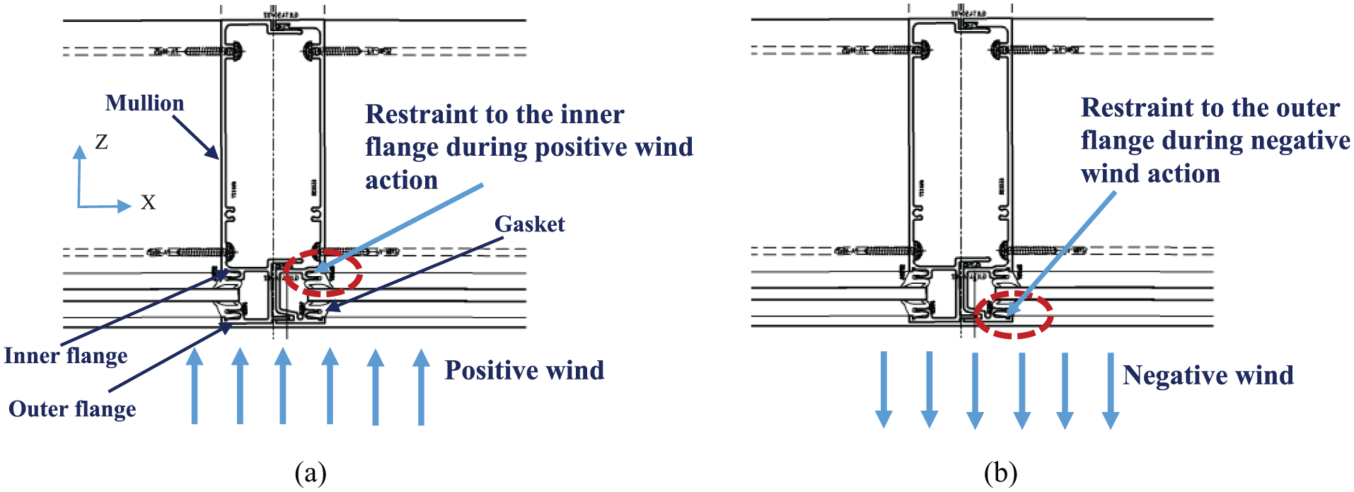
Glass panel system subject to wind actions: (a) positive wind action and (b) negative wind action.
The current method adapted in designing the aluminium mullion sections is based on the allowable stress method given in the ADM (2010) or AS/NZS 1664.1 (1997). To determine the bending capacity, it is checked first to determine whether any individual element buckles, and if it does, the critical stress is determined and then the section moment and flexural torsional buckling capacity are found by using complex formulae (ADM, 2010). Currently, the popular trend to design these thin-walled members of complex cross sections is based on the direct strength method (DSM) proposed by Schafer (2008). Zhu and Young (2009) investigated the applicability of DSM to design the tubular aluminium members under bending and compression actions. This method relates the elastic buckling capacity to the section and member capacities. Therefore, as the first step in this design method, it is important to understand the buckling behaviour of complex-shaped mullion sections shown in Figure 2.
It is a cumbersome task to find the buckling loads of these complex cross sections using hand solutions, and adapting a finite element approach would also be time-consuming. Finite strip analysis is the most suitable approach to examine the instability/buckling behaviour of these complex aluminium members subject to longitudinal stresses (bending and axial). Li and Schafer (2010) developed an open-source programme, CUFSM, based on finite strip analysis method, and this application facilitates easy determination of the various buckling loads and modes of thin-walled members of different lengths and sizes (Schafer and Adany, 2006). Previously, Wang (2006) has used the CUFSM software to determine the buckling load of E-type mullion section. The mullion sections subject to bending action could undergo three types of instabilities; local, distortional and flexural torsional buckling. The buckling modes and load factor versus half wave length plots could be different for aluminium extrusion sections compared to steel sections. Furthermore, due to the asymmetric nature of these mullions, and the lower elastic modulus of aluminium, buckling could occur at lower stress levels. This study uses CUFSM software to analyse the various buckling modes of complex-shaped male and female mullion sections restrained by glass as used in curtain walls and then investigates the applicability of DSM-based design approach for them.
Modelling and analyses of 650 series sections – male mullions
Development of CUFSM model
The 650 series 027 section (650-027 in Figure 2), which is commonly used among leading glass suppliers in Australia, was considered. It does not have a uniform thickness. In the CUFSM software, the thickness of a particular element cannot be varied. Hence, the male mullion section shown in Figure 2 was idealized into sections of different elements as shown in Figure 4(a). The AutoCAD drawing has more than 30 co-ordinates, and no facility is available in CUFSM to directly import the AutoCAD drawings or the co-ordinates of those drawings. Manually entering each of the node and element number in CUFSM for a particular mullion section is a cumbersome task since there are about 40 different nodes and elements in each mullion section. To facilitate this, a small AutoCAD application (PLIST) was loaded in AutoCAD, which enabled the transfer of nodal co-ordinates of the drawn polyline to an excel file. An excel spreadsheet was developed, which lists the node and element numbers based on the imported AutoCAD co-ordinates. The list could be copied and pasted to the cells of CUFSM. Supplementary data are provided with this article for the idealized 650-027 mullion section.
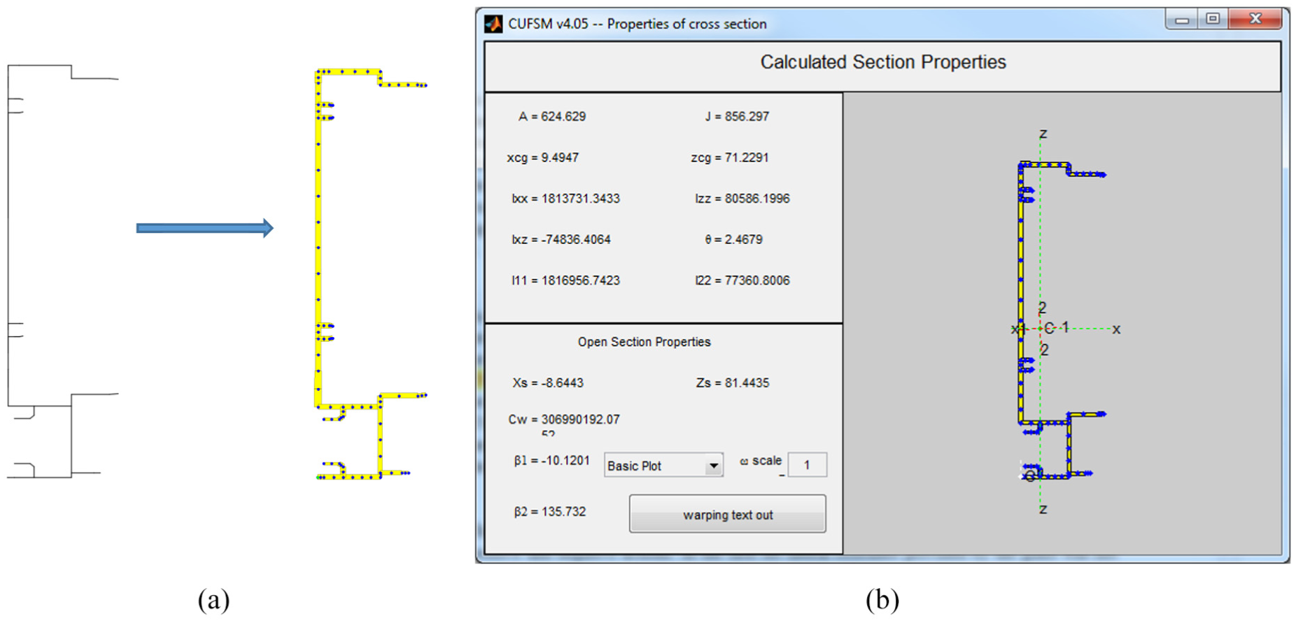
Modelling of 650-027 male mullion in CUFSM: (a) idealized model and (b) section properties.
The section properties of the male mullion were determined from the software ShapeDesigner (refer Supplementary Data). Similarly, the section properties of the idealized section were found from the CUFSM software and are given in Figure 4(b). There are some differences, especially in the torsional constant values, but they are small, and the area and the second moment of areas about the X- and Z-axes are about the same.
The mechanical properties of aluminium sections (6063T6 alloy) used in the modelling are summarized as follows (AS/NZS 1664.1, 1997): yield strength – 172 MPa, elastic modulus – 70,000 MPa, Poisson’s ratio – 0.32 and shear modulus – 26,515 MPa. These are the commonly used mechanical properties in Australia for aluminium design.
As seen in Figure 3, the glass is connected to one side of the mullion along its length. It is assumed that the glass provides a continuous lateral restraint along the section length when designing the mullion sections. In this study, analyses of the mullion sections were performed with and without glass restraints and then also with varying spring stiffness. In asymmetric sections, the principal axes are different to those axes where the forces are applied. However, if the sections are restrained against movement in one direction (X-X axis), the bending stresses (f) about that axis can be found from the basic equation (equation (1)) without finding the stress components in the principal axis. More details can be found in Ings and Trahair (1984). The restrained bending option available in the CUFSM was used for these mullion sections

where f is the bending stress, M is the bending moment about the x-axis, Ix is the second moment of area about the x-axis and y is the perpendicular distance from the centroidal x-axis to the point considered.
Buckling behaviour of unrestrained male mullion sections
Unrestrained male mullions subject to positive wind action
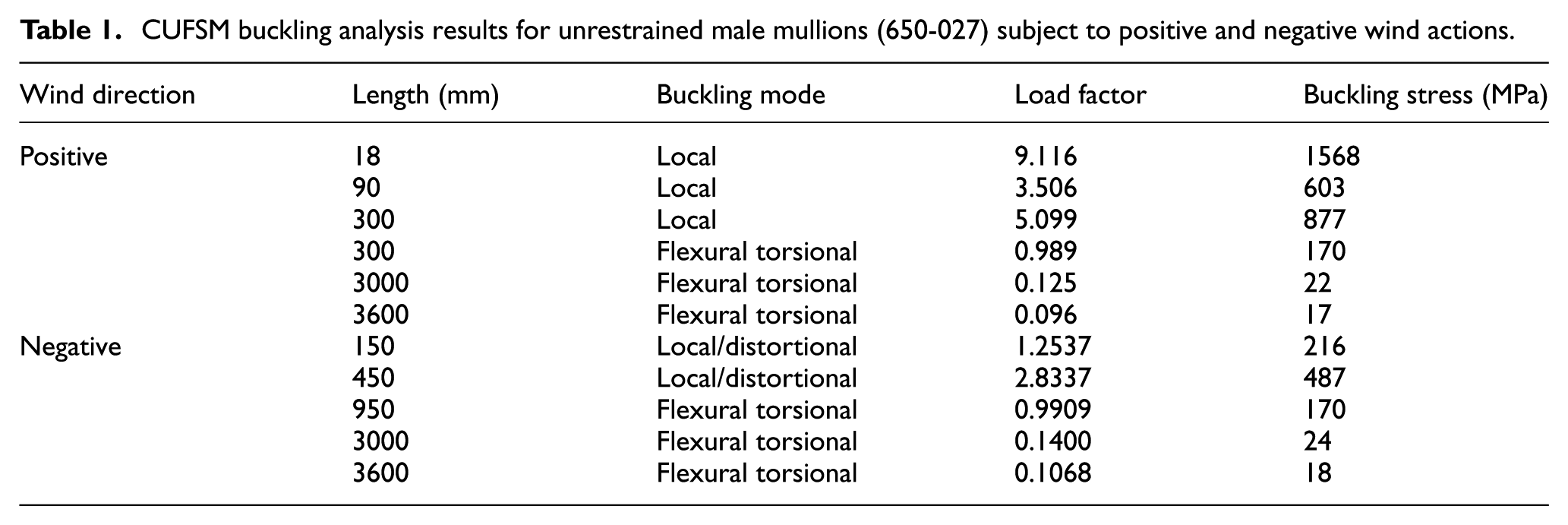
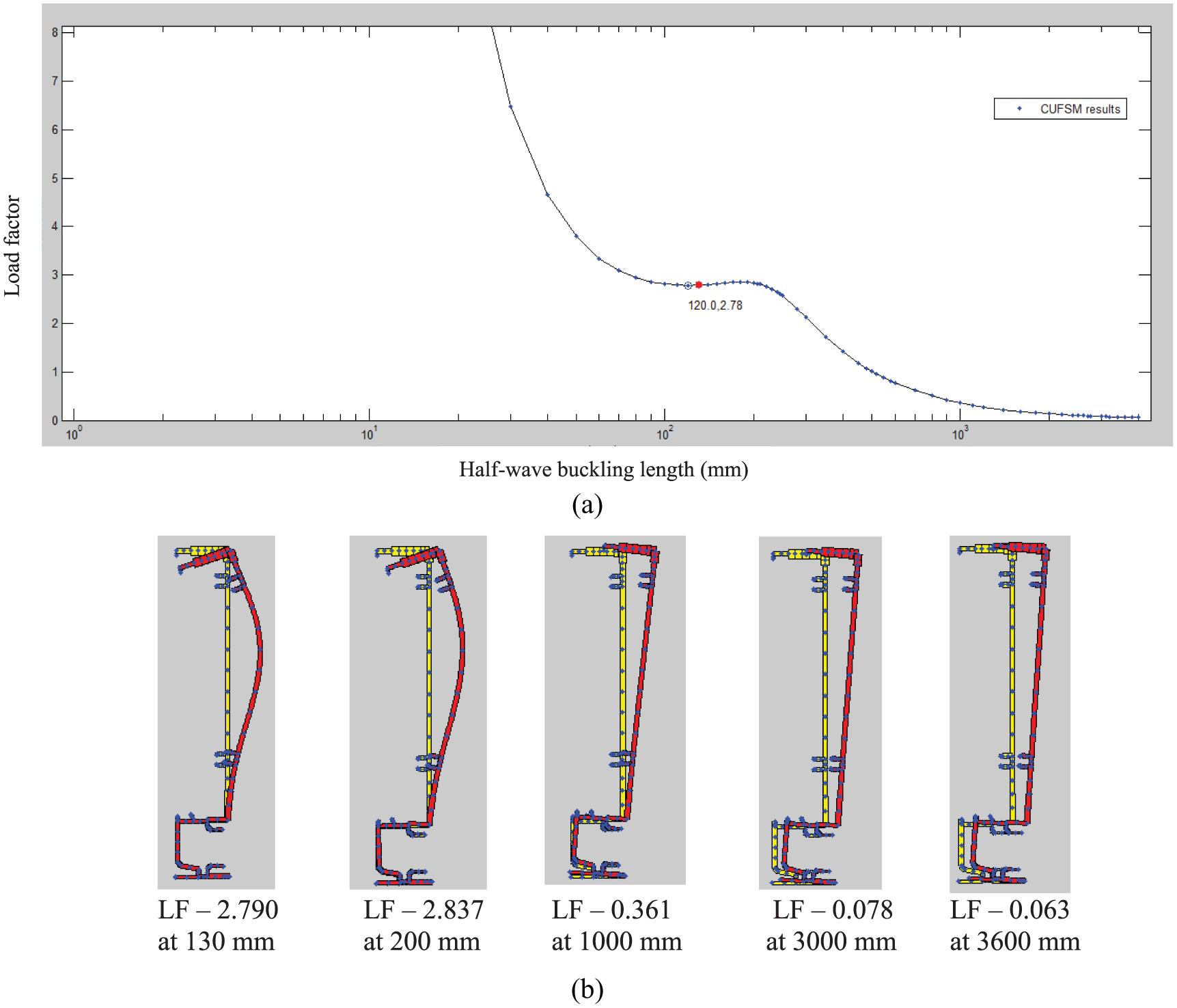
The first series of analyses was performed for 650–027 male mullion sections subject to positive action. In the first set, lateral restraint provided by the glass was omitted in the analyses. In CUFSM analyses, a uniform moment can be applied. However, a member with different moment distributions other than uniform moment cannot be modelled. The stress distribution and the tension/compression sides are shown in Figure 5(a) for positive wind action. The yield moment about the X-X axis is 3.95 kN m. Beam lengths of 1–4000 mm were considered in the analyses. The buckling analysis results for the positive wind action (Figure 3(a)) are given in Figure 6(a) and (b). Figure 6(a) presents the load factor versus half wave buckling length plot to show the variation of load ratio with increasing member length. Here, load factor is the ratio of the buckling and yield moments. The minima buckling occurs at a half wave length of 90 mm, where the load factor is 3.51 (buckling stress of 603.7 MPa in Figure 6(b) and Table 1). Figure 6(b) also shows that the buckling mode at this length is local. At a length of 300 mm also, local buckling is the critical mode, and the corresponding load factor is 5.0989. The buckling load factor is high; hence, most likely, this member might not undergo any component buckling before yielding failure. At a length of 900 mm, the buckling mode is flexural torsional buckling and the corresponding load factor is 0.989 (buckling stress of 170.1 MPa), and this shows that these sections can undergo flexural torsional buckling at very low stress levels. For 3000 and 3600 mm lengths, global buckling–flexural torsional buckling is the critical buckling mode, where the load factors are 0.125 and 0.0967, respectively.
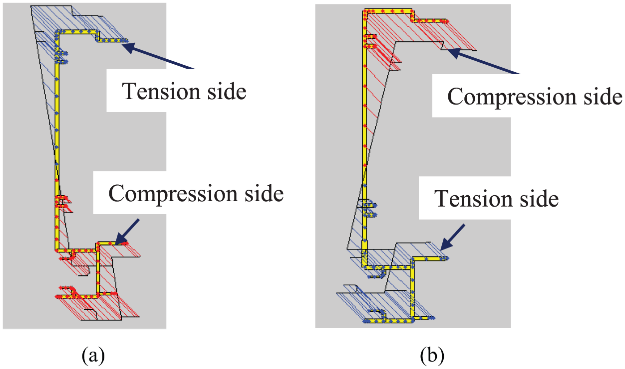
Bending stress distribution – male mullion section: (a) positive wind action – 650-027 and (b) negative wind action – 650-027.

Buckling analysis results of unrestrained male mullion (650-027) subject to positive wind action: (a) load factor versus half wave buckling length plot and (b) buckling modes.
CUFSM buckling analysis results for unrestrained male mullions (650-027) subject to positive and negative wind actions.
Unrestrained male mullions subject to negative wind action
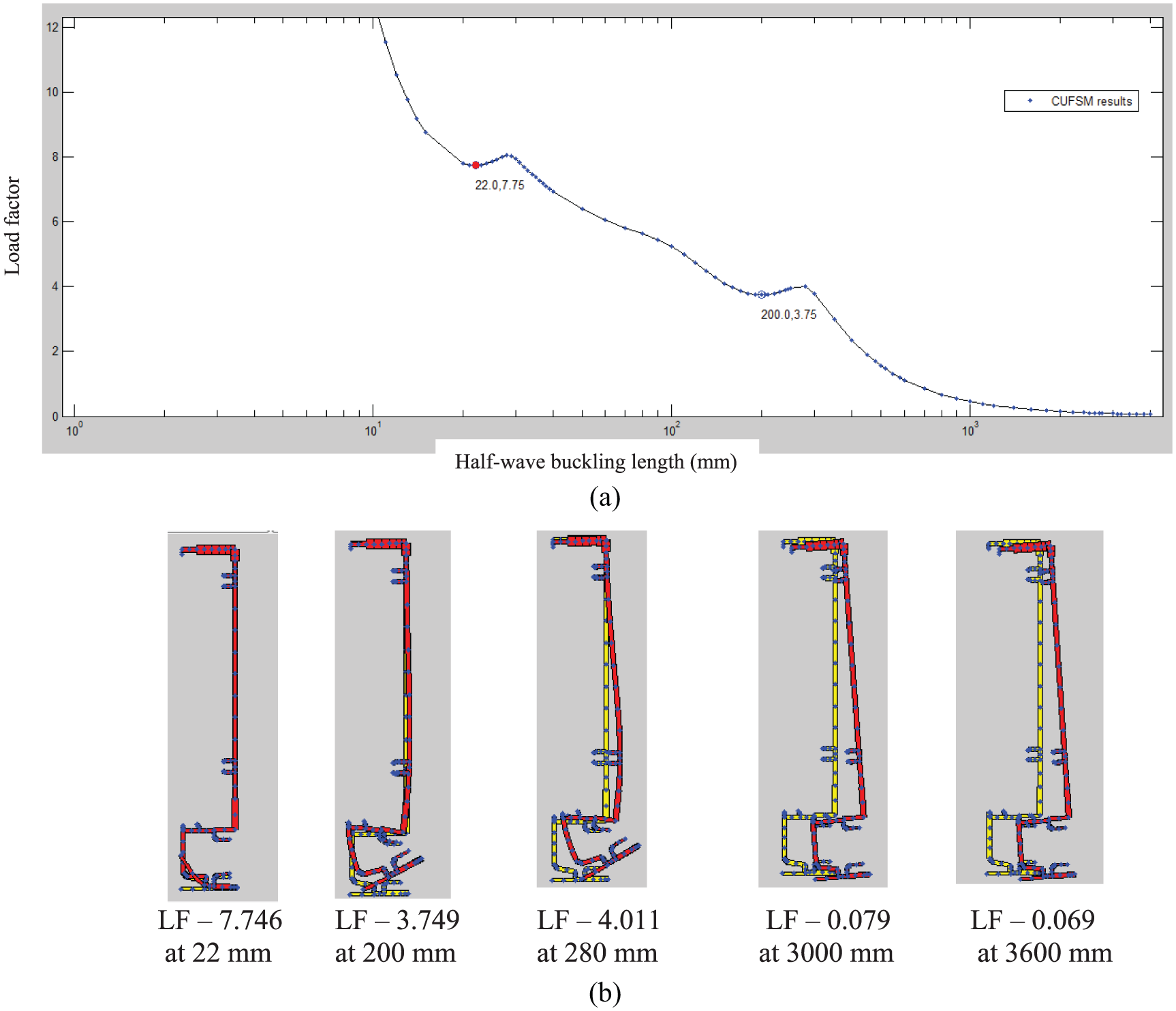
The second series of analyses was performed for 650-027 male mullion section subject to negative wind action (Figure 3(b)), and the lateral restraints were omitted. Figure 5(b) shows the stress distribution across the cross section and the tension/compression sides, and the yield moment is 3.95 kN m. The load factor versus half wave buckling length plot obtained from CUFSM analysis is shown in Figure 7(a).
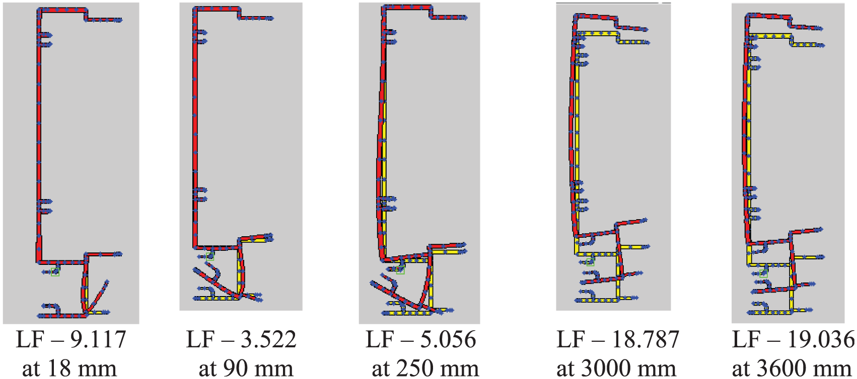
The minimum local buckling stress occurs at a half wave length of 150 mm, where the load factor is 1.25 (buckling stress of 216 MPa) –Table 1 and Figure 7(b). But a closer look at Figure 7(b) shows minor distortion of the flange element also, which is not common in thin-walled members. Importantly, the flange elements (Elements 1 and 2) buckle together rather than buckling as two individual elements. At a half wave length of 450 mm, it is subjected to local and distortional buckling as evident from Figure 7(b). At a length of 950 mm, the buckling mode is flexural torsional buckling, and the load factor is 0.991 (buckling stress of 170 MPa). For 3000 and 3600 mm lengths, flexural torsional buckling is the critical mode, where the load factors are about 0.140 and 0.107, respectively.
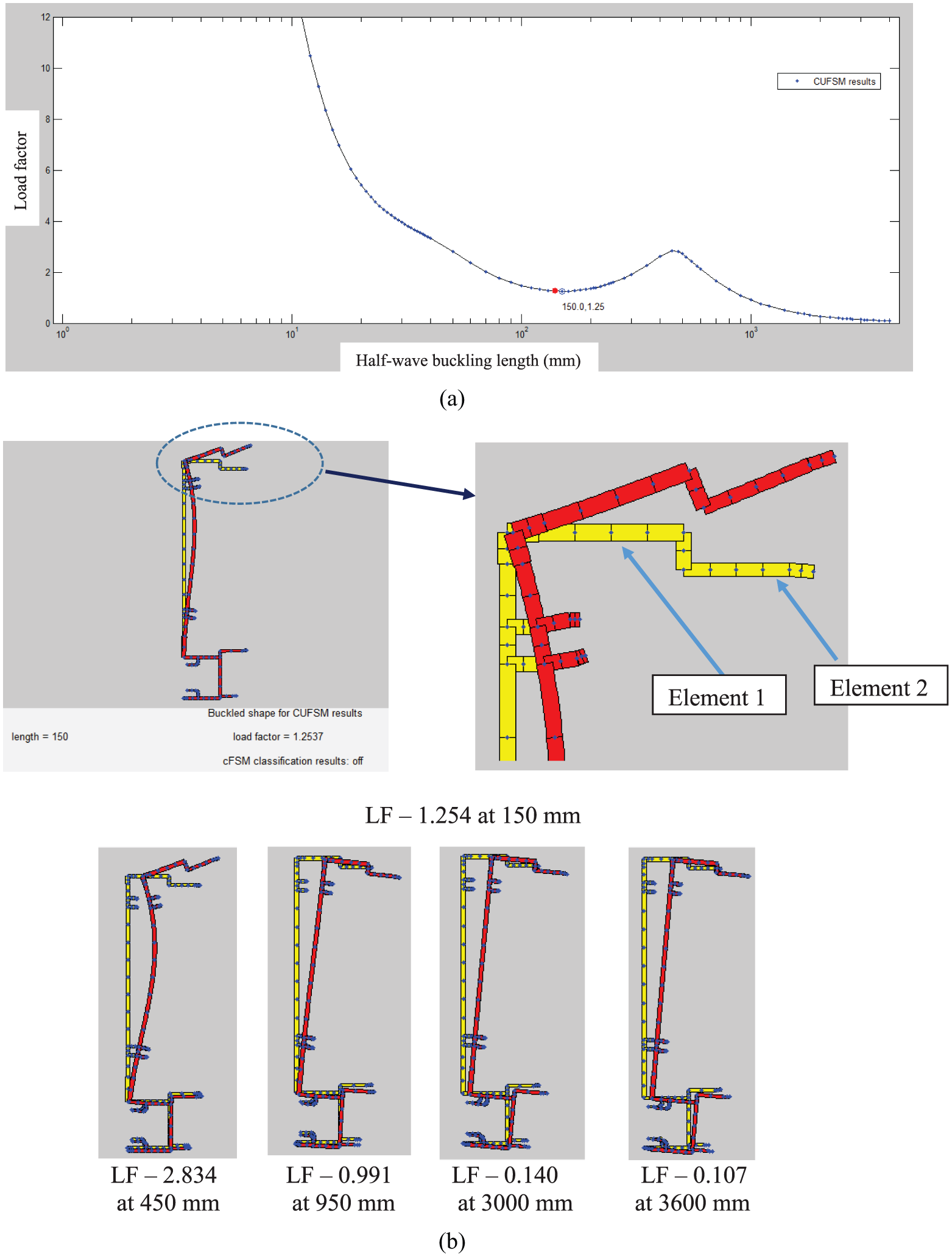
Buckling analysis results of unrestrained male mullion (650-027) subject to negative wind action: (a) load factor versus half wave buckling length plot and (b) buckling modes.
Overall, buckling analyses of unrestrained mullions show that these sections are more prone to flexural torsional buckling under both positive and negative wind actions if they are not restrained. Hence, the potential lateral restraints provided by the glass panel should be considered in the buckling analyses.
Buckling behaviour of restrained male mullion sections
Restrained male mullions subject to positive wind action
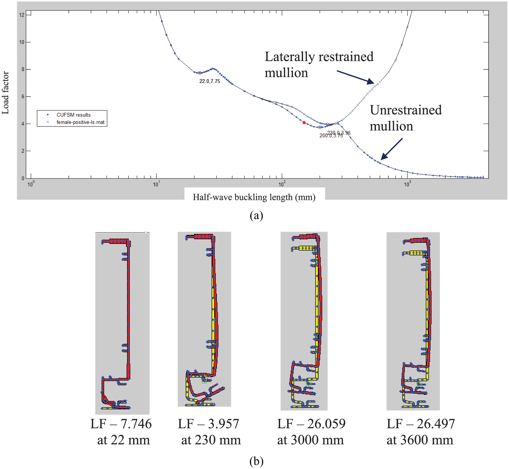
In curtain walls as shown in Figure 3, the glass is connected to the flanges on one side of the mullions through sealant or gasket connection. The glass will restrain the lateral movement of these flanges during wind action. During positive wind action, the load will be applied or concentrated on the inner flange (Figure 3(a)), and thus, the lateral restraint is expected to be mobilized at the loading point through friction. In this analysis, the lateral restraint was simulated at Point A as shown in Figure 8(a). The analysis results are provided in Table 2 and Figures 9(a) and 10. The half wave length versus load factor plot of sections without lateral restraints is also shown in Figure 9(a). There are significant differences between both plots.
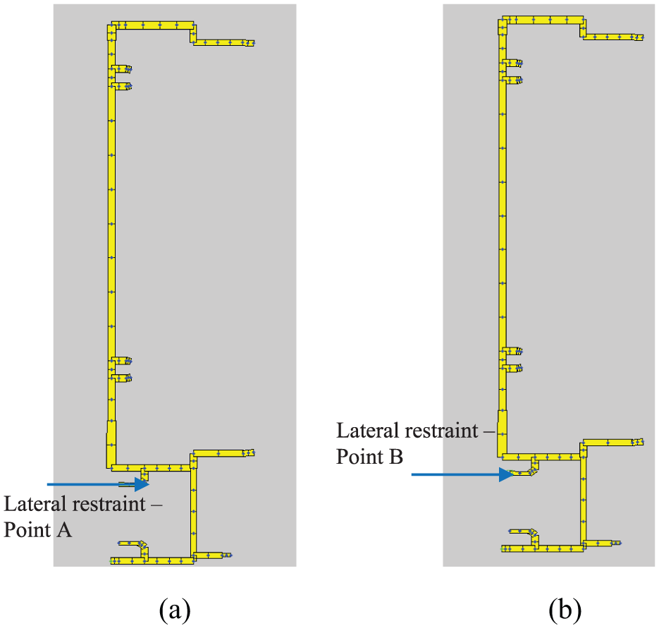
Lateral restraints provided to the male mullion section during positive wind action: (a) location A and (b) location B.
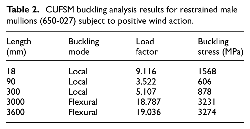
CUFSM buckling analysis results for restrained male mullions (650-027) subject to positive wind action.
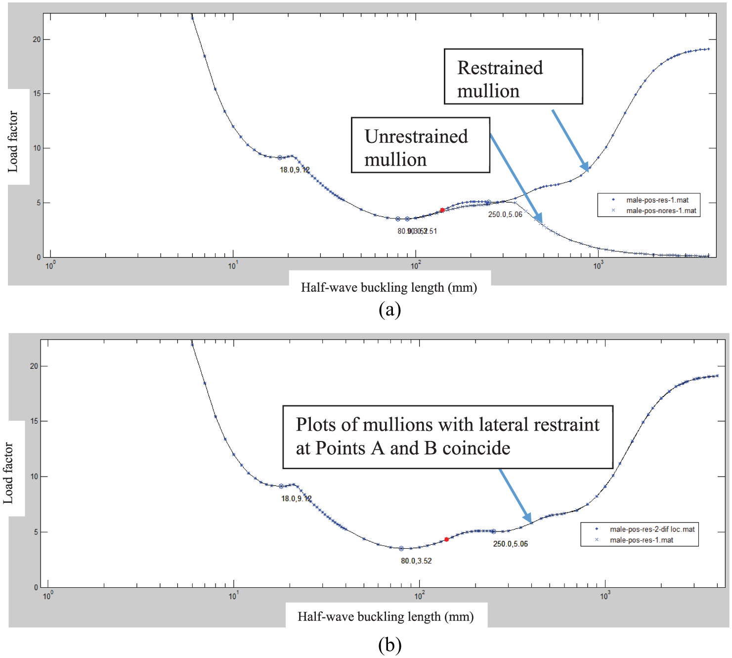
Load factor versus half wave buckling length plot of restrained male mullion (650-027) subject to positive wind action: (a) mullion with and without lateral restraints during positive wind action and (b) mullion with lateral restraints at different locations during positive wind action.
Buckling modes of laterally restrained 650-027 male mullion subject to positive wind action.
The positive wind action induces compressive stresses on the outer flange, which is restrained by the glass. Therefore, the compression flange is unable to move laterally, thus eliminating the flexural torsional buckling of mullions. As evident from Figure 9(a), the buckling plots of both mullions (laterally restrained and unrestrained) almost coincide up to a length of 350 mm. Thereafter, the plot of unrestrained mullion slopes down while that of restrained mullion goes up due to the elimination of flexural torsional buckling. Buckling modes for varying lengths are shown in Figure 10. As evident from Figure 10, flexural torsional buckling was not observed in the 3000 and 3600 mm long mullions with lateral restraints, whereas Figure 6(b) showed severe flexural torsional buckling in the 3000 and 3600 mm long unrestrained mullions subject to positive wind action.
Influence of lateral restraint location on the buckling behaviour of male mullion subject to positive wind action
Buckling analyses were conducted to determine whether the location of the lateral restraint along the flange width has any influence on the load factor versus half wave length plot. For this purpose, lateral restraint was applied at two different locations as shown in Figure 8 (Points A and B). The analyses were performed, and the results are plotted in Figure 9(b). This figure demonstrates that the lateral restraint location along the flange width did not affect the buckling behaviour of the laterally restrained mullion sections – a useful outcome.
Restrained male mullions subject to negative wind action
During the negative wind action, the load is mainly transferred to the outer flange (Figure 3(b)) through the glass panels, and the lateral restraint is expected to be acting on that flange. Therefore, for the negative wind action, the restraint was defined in CUFSM at the outer flange of the mullion as shown in Figure 11(a). Figure 11(b) compares the buckling plots of mullions with and without lateral restraints. It depicts that there are no significant differences in the plots since the compressive stresses occur at the inner flange, which is unrestrained. Buckling modes for varying lengths are shown in Figure 12, and at 3000 and 3600 mm lengths, flexural torsional buckling modes are observed. They are the same as shown in Figure 7(b) for unrestrained male mullions.
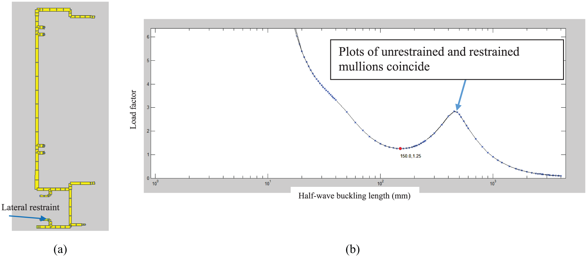
Buckling analysis results of unrestrained and restrained male mullion (650-027) subject to negative wind action: (a) lateral restraint location during the negative wind loading and (b) load factor versus half wave buckling length plots.

Buckling modes laterally restrained 650-027 male mullion subject to negative wind action.
Comparison of the buckling behaviour of mullions with and without return lips
This analysis compares the buckling behaviour of the aluminium mullion Sections 1 and 2 (Figure 13(a) and (b)). The difference between these sections is that Section 2 has a straight flange which is similar to the flange of a channel section. This will depict the benefit of the return lip of Section 1 (Figure 13(a)). Analyses were conducted and the load factor versus buckling half wave length plots of Sections 1 and 2 are shown in Figure 13(c). Both plots coincide after a length of 450 mm. After this length, the flexural torsional buckling becomes the dominant buckling mode, and the results show that return lip does not provide any benefits for flexural torsional buckling as this is apparent since this return lip will not significantly alter the second moment of area, torsion constant and warping constant. However, for lengths less than 450 mm, the return lip provides significant benefit as evident from Figure 13(c). The critical load factor for Section 2 is 1.02; hence, the critical buckling stress is 175.4 MPa, while that of Section 1 is about 23% higher (215 MPa) than Section 1. This shows the benefit of the increased local buckling capacity due to the provision of the return lip. Figure 13(d) shows the local buckling mode of Section 2. In conclusion, although this return lip is provided to increase the connectivity between the couple mullions, it also increases the local buckling capacity.
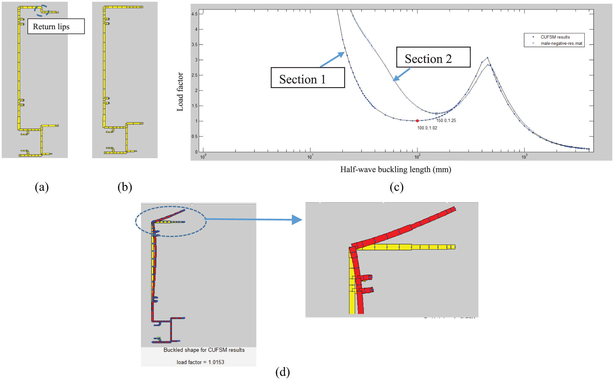
Buckling analysis results of (a) Section 1 and (b) Section 2. (c) Load factor versus half wave length plots. (d) Buckling mode of Section 2 at local buckling half wave length of 100 mm.
Buckling behaviour of mullions with lateral restraints provided via spring elements
Although façade engineers assume that full lateral restraints are provided by the glass to the mullions in design, in some instances (finite element modelling), a spring constant of 1 N/mm/mm is assumed to simulate the lateral restraints provided by the glass. Glass restraint is continuous along the mullion length, and continuous spring constraints can also be simulated in CUFSM where a spring can be attached to any node (Figure 14(a)). The spring constant can be applied as a constant value or as varying with member length. In this study, different spring stiffness values (1, 0.1 and 0.01 N/mm/mm) were used in CUFSM, and the analyses were performed. Negative wind action was not considered as it was shown in section ‘Restrained male mullions subject to negative wind action’ that even assuming full lateral restraint did not affect the buckling behaviour/plot. For a male mullion section subject to positive wind action with spring stiffness (1 N/mm/mm), the minimum load factor for flexural torsional buckling is about 2.67. Hence, most likely this mode of buckling cannot be expected in this 650-027 mullion section. The half wave length versus load factor plots of unrestrained mullion section and mullion section with spring lateral restraint 0.01 N/mm/mm are almost the same. Figure 14(b) provides a good understanding of the buckling behaviour of mullion sections with lateral restraints provided by spring elements of varying stiffness. Considering these results, an appropriate spring stiffness in the range of 0.1–1.0 is most suitable to simulate glass panel restraints. As a conservative approach, 0.1 N/mm/mm can be used. Full-scale façade test results are needed to confirm this.
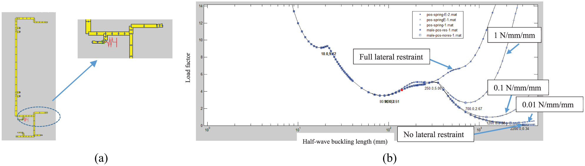
Buckling analysis results of 650-027 mullion under positive wind action and with spring restraints: (a) spring element usage for 650-027 mullion and (b) load factor versus buckling wave length plots.
Modelling and analyses of 650 series sections – female mullions
In the unitized panel system, male and female mullions are locked together to form the building envelope. The female mullion section (650-028) commonly used is shown in Figure 2. Buckling analyses were performed with and without considering the lateral restraints from the glass. The methodology used was identical to that described for male mullions in section ‘Modelling and analyses of 650 series sections – male mullions’. The buckling analysis results showed that the behaviour of female mullions is similar to that described for male mullions. Hence, only the selected results of load factor versus the half wave buckling length plots and buckling modes are presented without detailed explanations (Figures 15 to 17).
Buckling analysis results of unrestrained female mullions (650-028) subject to negative wind action: (a) load factor versus buckling wave length plot and (b) buckling modes.
Buckling analysis results of unrestrained female mullions (650-028) subject to positive wind action: (a) load factor versus buckling wave length plot and (b) buckling modes.
Buckling analysis results of laterally restrained and unrestrained female mullion (650-028) subject to positive wind action: (a) load factor versus buckling wave length plots and (b) buckling modes of restrained mullion.
Applicability of the CUFSM buckling analysis results in the mullion design
This section investigates the applicability of CUFSM buckling analysis results to determine the structural capacity of mullions. To consider a larger range of section slenderness, a simple mullion with geometry similar to 650-027 mullion, but with uniform thickness, was considered (Figure 18(a)). The thickness of this mullion was changed from 0.8 to 8 mm, which resulted in cross-sectional slenderness in the range of 30–160 based on ADM (2015). Therefore, the investigated mullion sections included compact sections, and sections subject to elastic and inelastic local buckling. The CUFSM buckling analyses were performed and the obtained critical local buckling stresses are summarized in Table 3. The load factor versus half wave buckling length of 1-mm-thick section is shown in Figure 18(b).
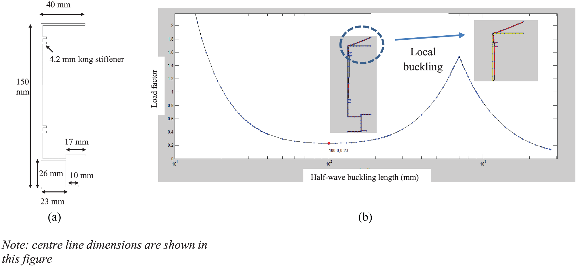
CUFSM buckling analysis plot and critical buckling mode of 1-mm-thick section used in the parametric study: (a) mullion geometry considered in the parametric study and (b) CUFSM buckling analysis plot and critical buckling mode of 1-mm-thick section.
Comparisons of section moment capacities of mullions from FEA and DSM (ADM, 2015).
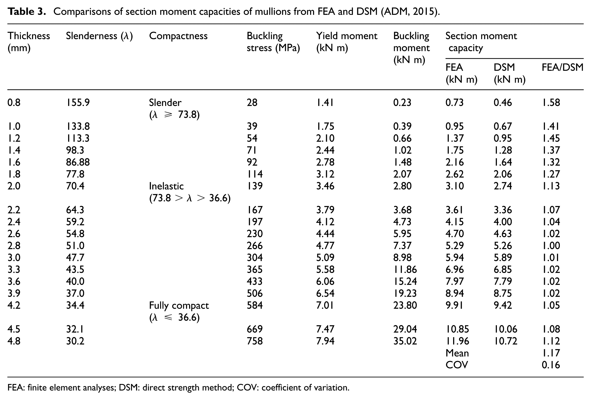
FEA: finite element analyses; DSM: direct strength method; COV: coefficient of variation.
The use of these critical local buckling stress values in determining the ultimate section moment capacity of mullions is evaluated in this study. These critical buckling stresses were used in the DSM given in ADM (2015). The mullion section moment capacities were determined from finite element analyses (FEA) using ABAQUS under negative wind action. Details of the finite element modelling procedure are given next, followed by the comparison of FEA and design rule predictions.
The finite element models developed were similar to the ones developed to determine the section moment capacity of cold-formed steel beams in Anapayan et al. (2011) and Siahaan et al. (2016). The developed models represented a four-point bending setup. The aluminium mullions were modelled using S4R shell elements with 4 mm × 4 mm mesh. Figure 19 presents the finite element models including the support and symmetric boundary conditions and the loading points. Furthermore, in order to prevent any X-axis displacement, a continuous lateral restraint was defined at the outer flange along the mullion length to simulate the restraint provided by the glass panels. The geometric imperfection was applied in the shape of the critical local buckling mode according to Schafer and Pekoz (1998). A local geometric imperfection value of 0.004b was used, based on the allowable tolerance given in Aluminium standards and data metric SI (Aluminium Association, 2013). The limitation of the developed models is that they need to be validated using experiments in the future.
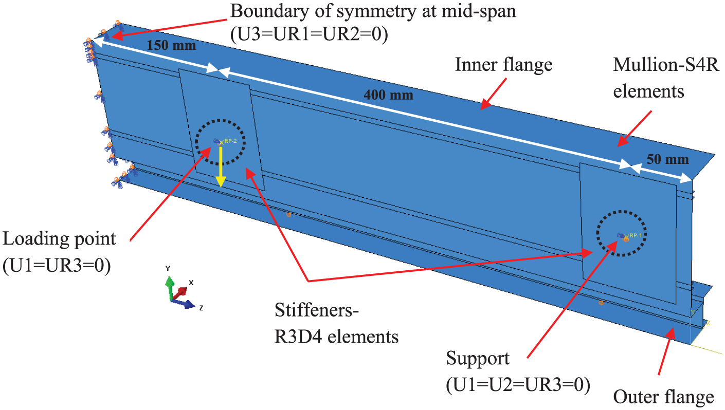
Finite element model.
The yield strength, ultimate strength and elastic modulus of mullion were taken as 172, 207 and 70,000 MPa, respectively, from AS/NZS 1664.1 (1997). Eurocode stress–strain model (Eurocode 9 Part 1.1; BS EN 1999-1-1:2007, 2007) was used to determine the engineering stress–strain model (equations (2) and (3)). The corresponding true stress and logarithmic plastic strain data were used as input in ABAQUS
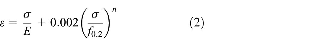
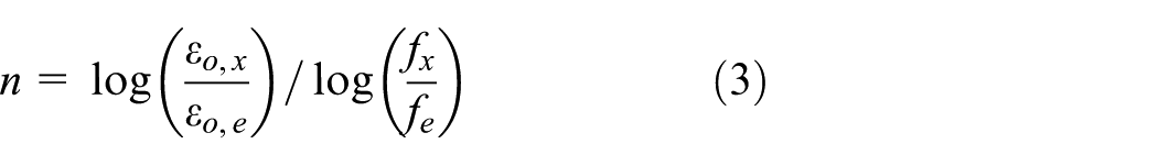
where n is the strain hardening exponent, fx is the reference stress, fe is the conventional limit of elasticity, ε o, x is the reference strain and ε o, e is the strain corresponding to the stress fe
FEA were performed under negative wind action using Modified Riks analysis method, and the results are summarized in Table 3. The mullions failed by section yielding where local buckling was observed in slender sections or in sections subjected to inelastic buckling. The section moment capacities of mullions were predicted using the DSM given in ADM (2015), where the buckling stresses obtained from CUFSM analyses were used to determine the cross-sectional slenderness of mullions. The DSM equations (ADM, 2015) to calculate the section moment capacity (Mnl) are given in the following

The allowable stress (Fb) is found using the following equations and limits
For


For
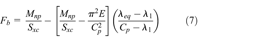
For
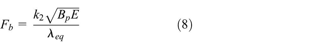
where
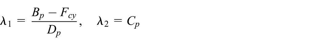
Cp, Bp and Dp are buckling coefficients which are given in Table B.4.2 of the ADM (2015).
Sxc is the section modulus about the compression side of the X-axis and Mnp is the nominal flexural strength calculated by

where Z is the plastic modulus of the section.
The ratios between the section moment capacities obtained from FEA and DSM design rules are also given in Table 3 and Figure 20. The DSM (ADM, 2015) predictions agree well with the FEA results of compact mullion sections and those subject to inelastic buckling, as reflected by the mean FEA to design rule prediction ratios of 1.08 and 1.04, respectively. However, the predictions were conservative for slender mullion sections with a mean FEA to DSM prediction ratio of 1.40. The mean and coefficient of variation (COV) for the FEA to design rule prediction ratios considering all the mullion sections are 1.17 and 0.16, respectively. This shows that the DSM in ADM (ADM, 2015) can be conservatively used to predict the section moment capacity of aluminium mullion sections subject to local buckling.
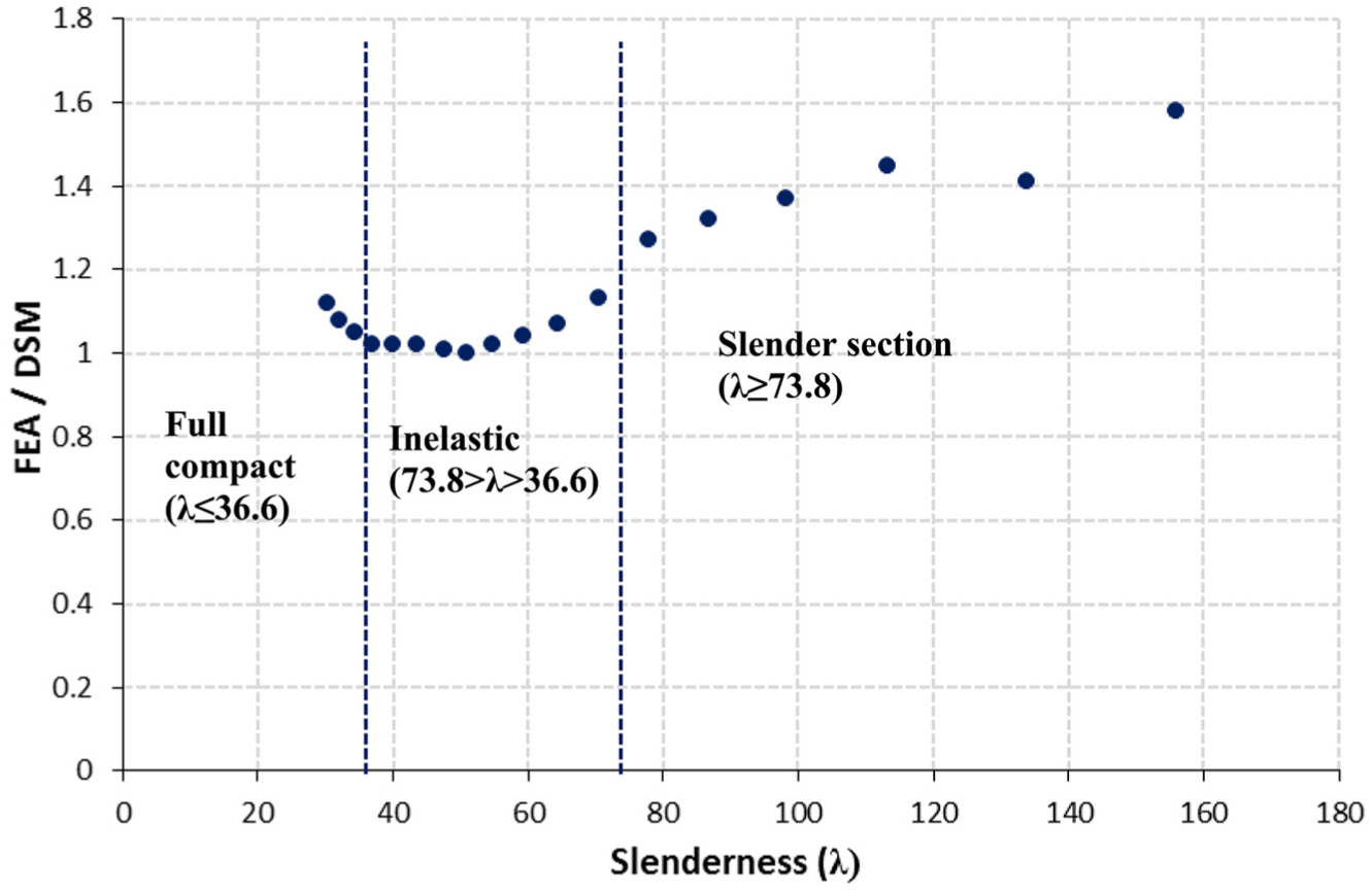
FEA/DSM ratio versus slenderness plot.
This section has demonstrated the direct applicability of buckling analysis results from CUFSM to determine the section moment capacity of aluminium mullion sections. Similarly, the member moment capacity can also be determined using the same approach. The use of DSM simplifies the moment capacity calculations of complex-extruded aluminium mullion sections, compared to the other approaches such as the limiting stress method and the total moment capacity approach (ADM, 2015 and Kim and Pekoz, 2003). The CUFSM buckling analysis software can be easily used to find the buckling stresses of complex-shaped mullion sections, which form the major input to the DSM calculations.
Conclusion
This article has presented an investigation into the buckling behaviour of complex-shaped aluminium mullion sections, where the finite strip analysis software ‘CUFSM’ was used. The aluminium mullion sections were simplified into elements of different thicknesses and were modelled using CUFSM. Two commonly used sections, 650-027 male and 650-028 female mullions, were considered. Analyses were performed with and without considering the availability of glass panel restraints for both negative and positive wind actions. The results showed that the potential lateral restraints provided by the glass panels can significantly improve the flexural buckling behaviour of mullion sections subject to positive wind action as compression flanges are restrained. The mullions with a spring constant of 1 N/mm/mm appeared to simulate fully restrained conditions. An appropriate spring stiffness in the range of 0.1–1 N/mm/mm can be used in CUFSM to simulate the glass panel restraint to mullions. Furthermore, it was found that the provision of return flanges to enable a good connectivity between the male and female mullions contributed to the increase in local buckling capacity of mullion sections.
Due to the increasing usage of complex-shaped thin-walled steel and aluminium members, the use of DSM is becoming popular, which requires a good understanding of the buckling behaviour of mullion sections. This study has provided good understanding of the buckling behaviour of male and female mullion sections under both positive and negative wind actions including buckling plots and modes. Importantly, it has demonstrated the direct applicability of buckling analysis results from CUFSM to determine the moment capacities of aluminium mullion sections.
Supplemental Material
supplementary_data – Supplemental material for Buckling behaviour and design of complex-shaped aluminium mullion sections
Supplemental material, supplementary_data for Buckling behaviour and design of complex-shaped aluminium mullion sections by Sivakumar Kesawan and Mahen Mahendran in Advances in Structural Engineering
Footnotes
Acknowledgements
The authors would like to thank QUT for providing all the necessary support with the computing facilities and The Australian Research Council for providing funding to the project (LP150101073).
Declaration of Conflicting Interests
The author(s) declared no potential conflicts of interest with respect to the research, authorship and/or publication of this article.
Funding
The author(s) disclosed receipt of the following financial support for the research, authorship, and/or publication of this article: Sivakumar Kesawan’s salary was paid from Australian Research Council funding for this research project.
Supplemental Material
Supplemental material for this article is available online.
References
Supplementary Material
Please find the following supplemental material available below.
For Open Access articles published under a Creative Commons License, all supplemental material carries the same license as the article it is associated with.
For non-Open Access articles published, all supplemental material carries a non-exclusive license, and permission requests for re-use of supplemental material or any part of supplemental material shall be sent directly to the copyright owner as specified in the copyright notice associated with the article.