
Abstract
Extensive research has been conducted on the replacement of steel rebars with fibre-reinforced polymer rebars to eliminate the steel corrosion problem in conventional steel bar–reinforced concrete structures. However, as the performance of fibre-reinforced polymer rebars is substantially inferior in compression (due to issues such as fibre micro-buckling) than in tension, their use in concrete columns is generally not recommended; this poses a significant challenge when a steel-free structure is needed. This article presents a novel steel-free hybrid rebar developed at The Hong Kong Polytechnic University that overcomes the above-mentioned problem. Such a hybrid rebar typically consists of a central fibre-reinforced polymer rebar, an external fibre-reinforced polymer confining tube and an annular layer of high-strength cementitious material such as ultrahigh-performance concrete. To demonstrate the performance of these hybrid rebars, results from a series of preliminary tests and associated modelling work are presented in the article. These results indicate that (1) the fibre-reinforced polymer rebar at the centre is well supported against bar buckling and fibre micro-buckling, (2) the compressive strength of the fibre-reinforced polymer material can be fully mobilized and (3) the stress–strain response of hybrid rebars can be designed to resemble an elastic–plastic response with some post-yielding hardening.
Keywords
Introduction
The deterioration of existing structures due to steel corrosion has been a major issue around the world. Steel-reinforced concrete (steel-RC) structures are the major type of structures suffering severe corrosion, particularly when they are exposed to marine and other aggressive environments. Over the past two decades, the use of fibre-reinforced polymer (FRP) reinforcing bars (rebars), which possess excellent corrosion resistance, to replace steel rebars to eliminate the steel corrosion problem in steel-RC structures has become widely accepted as an attractive solution. However, the use of FRP rebars as longitudinal reinforcement in concrete columns has been rather rare due to their much less favourable performance in compression. American Concrete Institute (ACI, 2015) does not recommend the use of FRP rebars as compression reinforcement, while American Association of State Highway and Transportation Officials (AASHTO, 2009) and Canadian Standards Association (CSA, 2012) recommend that the contribution from compressive FRP reinforcement be simply ignored in calculating the member capacity. The lack of acceptance of FRP rebars as compressive reinforcement is due to a number of significant concerns (Deitz et al., 2003; Kobayashi and Fujisaki, 1995; Sharbatdar, 2003; Wu, 1990): (1) fibre micro-buckling is likely to occur in FRP rebars under compression, and as a result, their compressive strength is known to be much lower than their tensile strength and cyclic loading may lead to significant damage; (2) FRP rebars can buckle easily due to a high strength-to-modulus ratio unless very well supported by stirrups or the surrounding concrete; and (3) even if these two problems do not occur, the compressive strength of FRP rebars can only be partially utilized in FRP-RC columns due to the much smaller strain of concrete at compressive failure than the ultimate compressive strain of FRP rebars.
In order to tackle the problems mentioned above, a novel steel-free hybrid rebar is proposed here (Figure 1): such a hybrid rebar typically consists of a central FRP rebar (normally manufactured by pultrusion with all fibres aligned in the longitudinal direction for the resistance of axial stresses), a thin external FRP confining tube (normally prefabricated by filament winding with suitable fibre orientations to provide desired levels of stiffness and resistance in both the hoop and the axial directions) and an thin annular layer of high-strength cementitious material such as ultrahigh-performance concrete (UHPC) without coarse aggregate or with coarse aggregate of sufficiently small size. The outer surface of the FRP tube should be provided with appropriate surface features to enhance its bond behaviour in concrete. In addition to the elimination of steel corrosion in conventional steel-RC structures, these hybrid rebars are particularly useful in situations where the use of steel reinforcement must be avoided, including seawater sea-sand concrete (SSC) structures (Teng, 2014; Teng et al., 2011, 2016) and hospital rooms’ housing magnetic resonance imaging (MRI) facilities. To demonstrate the performance of these hybrid rebars, a series of preliminary tests are presented in the remainder of the article.
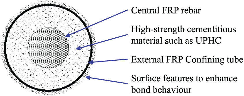
Cross section of hybrid rebars.
Experimental study
In the preliminary experimental study, six hybrid bar specimens in three pairs were prepared and tested, with each pair having normally the same properties (Table 1). These specimens all had a diameter (the inner diameter of the external FRP tube) of 50 mm and a height of 150 mm. For ease of implementing these tests without compromising their usefulness for the intended purpose of performance demonstration, the test specimens were made as follows: the external FRP tube was replaced by a carbon fibre–reinforced polymer (CFRP) jacket which was wrapped on a cured high-strength cement mortar bar reinforced with a central glass fibre–reinforced polymer (GFRP) rebar. The fibres in the GFRP rebar were oriented in the longitudinal direction as usual to resist axial stresses, while the fibres in the CFRP tube (jacket) were oriented in the hoop direction to provide confinement.
Details of hybrid rebars.

GFRP: glass fibre–reinforced polymer; CFRP: carbon fibre–reinforced polymer.
One pair of the test specimens did not have a CFRP jacket to serve as the control specimens. The nominal thicknesses of the other CFRP jackets were 0.165 mm (one ply) and 0.33 mm (two plies), respectively. The FRP jacket had fibres oriented in the hoop direction with an overlapping zone spanning a circumferential length of 50 mm. The GFRP rebar had a diameter of 24.1 mm. The outer surface of the FRP tube did not have bond-enhancing features as they have little effect on the axial compressive behaviour of hybrid rebars. For GFRP bars used in this study under tension, the tensile strength, elastic modulus and ultimate tensile strain were 698 MPa, 46.2 GPa and 1.59%, respectively, which were obtained by the bar manufacturer following ASTM D7205/7205M-06. The compressive strength of the high-strength cement mortar was 74.3 MPa from five 50-mm cube tests conducted according to ASTM C109/C109M-13. Two 50 mm × 150 mm circular cylinders made purely of the same cement mortar were also tested under axial compression, and the average compressive strength and elastic modulus were 61.9 MPa and 33.2 GPa, respectively. For the external CFRP jacket, the tensile strength, elastic modulus and ultimate strain obtained from flat coupon tests conducted following ASTM D7565-10 were 2340 MPa, 234 GPa and 1.0%, respectively.
Two linear variable differential transformers (LVDTs) at diametrically opposite positions and strain gauges were used to obtain the total axial shortenings or strains, and only data from the former are used in this article. Four strain gauges with a gauge length of 10 mm were also installed at the mid height of the specimen (90° apart from each other) to record hoop strains of the CFRP jacket. All compression tests were carried out using an MTS machine with a displacement control rate of 0.09 mm/min. The axial load was applied on both the pultruded GFRP bar and the cement mortar simultaneously (Figure 2).
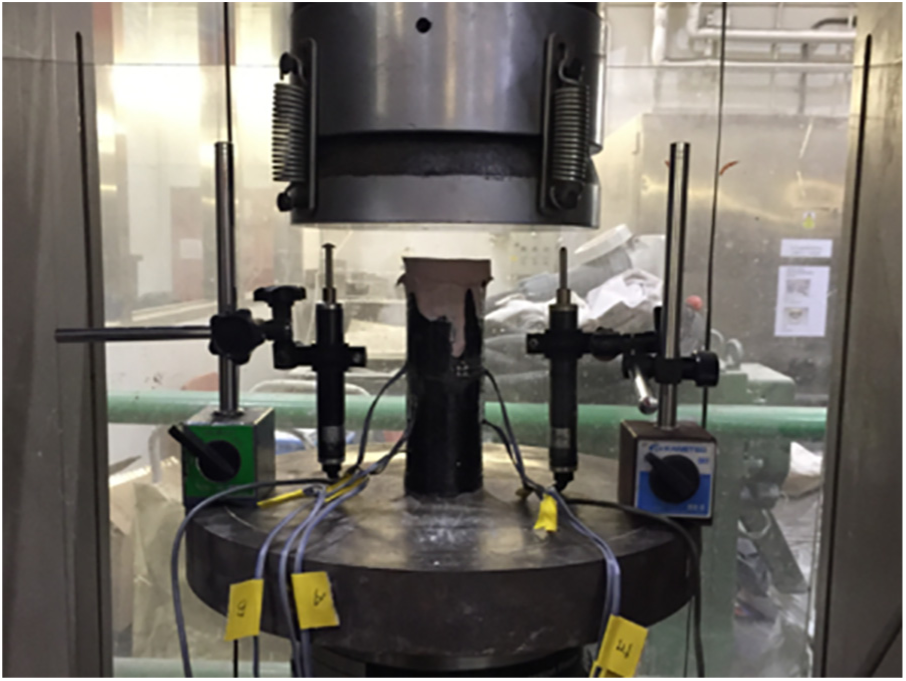
Experimental setup.
Test results and discussions
The typical failed specimens are shown in Figure 3. The axial load–axial strain (from LVDTs) curves of all specimens are shown in Figure 4. Here, compressive loads, stresses and strains are taken to be positive. For the specimen F0B-1,2 (i.e. control specimens with no CFRP jacket), the cement mortar formed small vertical cracks at an axial strain of around 0.3%, where an axial load drop occurred; afterwards, the axial load recovered and increased monotonically until the crushing of cement mortar and fibre micro-buckling of GFRP bar near one end of the specimen (Figure 3(a)). For specimens F1B-1,2 (i.e. specimens with a one-ply CFRP jacket) and F2B-1,2 (i.e. with a two-ply CFRP jacket), their loads increased monotonically until final failure, which was caused by the rupture of CFRP jacket (Figure 3(b)). It is believed that the cement mortar unloaded suddenly at CFRP jacket rupture, which caused the load on the GFRP bar to increase rapidly, resulting in the local shear failure at one end of the GFRP bar. Local bar buckling or fibre micro-buckling could not be identified in the failed specimens, indicating that the central GFRP bar was well confined/supported by the cement mortar under FRP confinement.
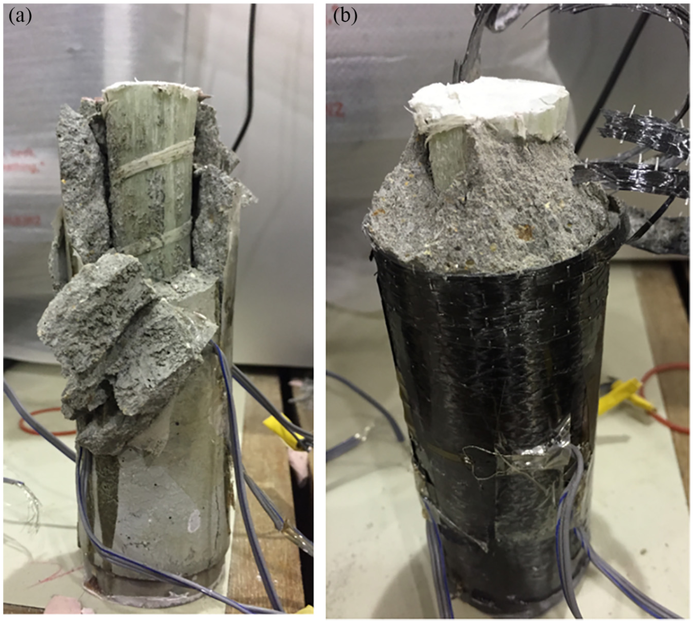
Typical specimens after failure: (a) F0B-1 and (b) F2B-2.

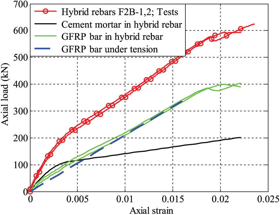
Axial load–axial strain curves.
Figure 4 also shows a comparison between experimental results and predictions for the axial load–axial strain curves of specimens F1B-1,2 and F2B-1,2. In making the predictions, two assumptions were adopted: (1) as no reliable stress–strain model is available for FRP-confined cement mortar, Jiang and Teng’s (2007) model, which provides close predictions for both normal-strength concrete and high-strength concrete confined by FRP, was assumed to be applicable and thus directly used to predict the behaviour of confined cement mortar in hybrid rebars; (2) the behaviour of the central GFRP bar was taken to be the same as that under tension. The predicted curves end at a point when the average hoop rupture strain of the CFRP jackets of specimen F1B-1,2 or F2B-1,2 is reached. Figure 4 shows that the predictions agree closely with the test results and the axial load–strain curves show a strong hardening response after ‘yielding’ due to the high level of confinement although the ultimate axial strains of the specimen F1B-1,2 are significantly underestimated.
Figure 5 examines the axial load contribution of GFRP bar in hybrid rebars. The axial load resisted by the cement mortar in a hybrid rebar was obtained as the product of its annular section area and the axial stress predicted using Jiang and Teng’s (2007) model. The average hoop rupture strain of the CFRP jackets of the specimen F2B-1,2 was used for making the predictions in Figure 5. The axial load resisted by the GFRP bar in a hybrid rebar was obtained as the difference between the total axial load acting on the hybrid rebar and the predicted axial load taken by the cement mortar. The axial load resisted by the GFRP bar in tension was obtained as the product of its sectional area, its tensile elastic modulus from the manufacturer and its tensile strain whose maximum value was taken to be that given by the manufacturer. Figure 5 shows that at the same axial strain value, the deduced load resisted by the GFRP bar in a hybrid rebar under axial compression is very similar to that resisted by the GFRP bar in tension. The GFRP bar in a hybrid rebar under compression is seen to achieve a larger ultimate strain than that under tension, probably due to the confinement provided by FRP-confined cement mortar. The above comparison indicates that the compressive behaviour of the FRP bar in a hybrid rebar can be expected to be similar to its tensile behaviour.
GFRP bar contribution in hybrid rebars.
Figure 6 shows stress–strain curves of hybrid rebars of various combinations of the three constituent materials (i.e. the central FRP rebar, the external FRP tube and UHPC in between) predicted using Jiang and Teng’s (2007) model. According to Zohrevand and Mirmiran (2011), Jiang and Teng’s (2007) model should be able to provide reasonable approximations of the behaviour of FRP-confined UHPC. It is very interesting to observe that the stress–strain response of hybrid rebars can be designed to suit the needs of a specific application (e.g. to exhibit an elastic–plastic response like that of steel or a strong post-yielding strain-hardening response).

Predicted stress–strain responses of hybrid rebars.
Concluding remarks
This article has presented a new form of steel-free rebars for use as compression reinforcement in concrete structures to eliminate the steel corrosion problem or to avoid interference caused by steel to MRI in hospitals and other facilities with a similar requirement. These rebars, referred to as hybrid rebars, consist of a central FRP rebar, an external FRP confining tube and an annular layer of high-strength cementitious material such as UHPC. Results from some preliminary tests and associated modelling work presented in the article indicate that they have excellent performance under compression: (1) as the FRP rebar at the centre is well supported by the cementitious material, FRP rebar buckling and fibre micro-buckling are both prevented; (2) the compressive strength of the FRP rebar can be fully mobilized; and (3) the stress–strain response of hybrid rebars can be designed to meet pre-set requirements (e.g. to exhibit an elastic–plastic response like that of steel or a strong post-yielding strain-hardening response). It is worth noting that in SSC structures (Teng, 2014; Teng et al., 2011), steel needs to be completely eliminated, so steel-free compressive rebars are an essential component, and therefore the proposed hybrid rebars are very promising in SSC structures as well.
Footnotes
Acknowledgements
The paper was initially presented at the 6th Asia-Pacific Conference on FRP in Structures held on 19-21 July 2017 in Singapore and published in the proceedings of the conference. The authors would like to thank the organizers of the conference and the editors of the conference proceedings for permission to include the paper in this special issue with only some very minor changes.
Declaration of Conflicting Interests
The author(s) declared no potential conflicts of interest with respect to the research, authorship and/or publication of this article.
Funding
The author(s) disclosed receipt of the following financial support for the research, authorship and/or publication of this article: This work was financially supported by the Hong Kong Research Grants Council (project no. PolyU 152634/16E) and The Hong Kong Polytechnic University (project account code: 1-BBAG).