



Abstract
Based on the superior lateral resistant performance of mega-X layout pattern, the concept of quasi-megastructure was put forward to introduce quasi-mega mechanism in residential buildings, using normal members only, avoiding large architecture space occupation of mega members. Unlike the megastructures that are dominated by their primary structures, the quasi-megastructures mainly realize a synergistic mechanism between the frame structure and quasi-mega braces. In order to investigate its deformation mechanism and reduce the lateral stiffness irregularity, a simplified method for evaluating interstory drift of high-rise quasi-megastructure was proposed, based on three fundamental assumptions. Thus, the interstory drift formula for any specific layout scheme of quasi-megastructure can be deduced. The formula was validated by different layout schemes. By this method, the interstory drift proportion of quasi-megastructure was investigated, showing that the interstory drift of a target story mainly consists of drift due to rigid body rotation, pure shearing drift, and shear-lag added drift. And the vertical stiffness irregularity of the original scheme was due to great changes of shear-lag added drift in different neighboring stories. Thereafter, stiffened schemes were proposed, which effectively eliminate the interstory stiffness irregularity by complementing a quasi-mega cantilever wall of full height. Compared with mega frame structure, the original scheme has a similar overall deformation mechanism, while the properly stiffened quasi-megastructure scheme behaves quite close to mega braced frame structure, both in deformation mechanism and in structural efficiency.
Keywords
Introduction
With the growing population density and scarcity of building land, high-rise residential structures become the mainstream of residential buildings nowadays. Almost in all the major cities in Asian countries, residential buildings are characterized with high-rise and high density (Smith and Willford, 2010). The planning of high-rise buildings is examined to alleviate both extremely crowded urban environments (Fan et al., 2013). Under this circumstance, constructing the residential structures with the most economic rationality is particularly important. For high-rise buildings, the resistance of structures to wind as well as to earthquake is the major factor for the selection of the structural system, which decides the consumption of materials and construction cost (Hoenderkamp et al., 2012).
A high-rise structural system can be classified into several basic groups, that is, rigid and semi-rigid frames, shear wall or braced frame structures, shear wall or truss-frame interactive structures, tube structures, and megastructures (Ali and Moon, 2007; Elnashai and Di Sarno, 2008). Recently, the development of industrialization and assemblage of construction has promoted the application of steel structures, especially in the earthquake region. For steel structures, steel braces are most used as the lateral resistant components in multi-story and high-rise buildings due to their great lateral resistant capacity. In earthquake zones, steel braces are more and more replaced by buckling-restrained braces (BRBs) to avoid their failure of buckling under earthquake action.
As a new type lateral force–resistant member, buckling-restrained steel plate shear wall (BRSPSW) is a competitive alternative in place of steel braces for high-rise residential steel structures, as BRSPSW is not only as superior as BRB in carrying lateral force and dissipating seismic energy, but also able to avoid the problem of braces in conflict with doors and windows (Matteis et al., 2010). BRSPSW can be infilled in frame structure (FS) to participate in lateral resistance, connected only with the top beam and bottom beam in the frame. According to the identical stiffness and strength principle, BRSPSW can be simulated by a pair of equivalent cross braces, which has been verified to be able to well simulate BRSPSW’s work mechanism and hysteretic characteristics (Sun et al., 2011). Thus, to simplify the analysis procedure, in this article, the braces are used in the models instead of shear walls.
To improve structural efficiency and seismic behavior of high-rise residential steel structures, one of the methods is to find the optimum component size of structures (Hasançebi et al., 2010, 2011). Nevertheless, in a designed bracing system, its effect is not significant. Adopting appropriate lateral component layout schemes may be a more effective way. Such behavior will also reduce the consumption of materials and construction cost. Yu et al., (2015) has put forward that in a simple frame system the stiffest brace pattern is mega-X brace layout, which is far better than the vertically arranged parallel diagonal brace pattern. Di Sarno and Elnashai (2011) find that compared with concentrically-braced frames (X bracing) the mega-X-braced frames are more effective, for their 50% reduction in lateral drift with 20% less bracing steel.
Considering from the engineering concepts, Ji and Ellis (1997) and Ji (2003) proposed three structural concepts for designing stiffer structures. The more direct, more uniform, or smaller the internal force path, the stiffer and more economical the structure. Based on that, Yu et al., (2015) further put forward that large vertical forces should be avoided and that the less nonzero-force members will be better. It has been found that the mega-X braces pattern is well in accord with the above concepts.
In practical engineering, the mega-X braces pattern has been widely applied, including the John Hancock Centre in Chicago and the Bank of China in Hong Kong. However, the application of the mega-X layout scheme (using cross braces instead of steel plate wall in the model) in a high-rise steel residential structure (Sun et al., 2015) resulted in an extremely irregular distribution of interstory stiffness (Figure 1(a)), although it achieved significant improvement in lateral stiffness compared with its counterpart braced frame structure (BFS; Figure 1(b)). As per the seismic codes (NBCC 1989; UBC 1997, IS 1893:2002, EC 8:2004, NBCC 2005, GB 5001-2010), a story in a structure is deemed to contain stiffness irregularity if its stiffness is less than 70% that of the adjacent story (Varadharajan et al., 2014). For structures with vertical stiffness irregularity, when they are subjected to earthquake action, internal forces tend to concentrate and form weak story within the structure due to the randomness and uncertainty of earthquake. It is harmful in terms of both structural safety and economy. There has been research on stiffness irregularity of ordinary structures done by Van Thuat (2013) and Kim and Hong (2011). However, the stiffness irregularity of the mega-X layout scheme above cannot be clearly explained by reference to the literature.
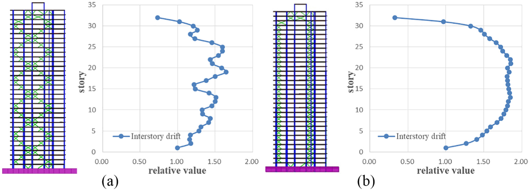
Interstroy drift of two different braces’ layout systems: (a) mega-X layout scheme and (b) braced frame structure.
In this article, a concept of the so-called “quasi-megastructure” will be put forward for the structures similar to the mega-X layout scheme above. By comparison with the models with different lateral resistant systems, it can be found that the lateral resistant mechanism of the quasi-megastructure is quite different from that of the megastructures. Thereafter, a simplified calculation method will be developed based on several general assumptions, to evaluate interstory drift of the quasi-megastructure, whereby the cause of stiffness irregularity will be illustrated. The stiffness irregularity will then be reduced by a stiffened layout scheme.
The concept of quasi-megastructure
Megastructure is a structural system with its main structure composed of mega members (including mega beams, mega columns, and mega braces). The geometric dimensions, sectional areas, and moment of inertia of the mega members are much larger than those of normal structural members. Therefore, normal members just play an auxiliary role in a megastructure. The main structure of a megastructure supports a large portion of lateral load, for it has great lateral stiffness (Banham, 1976).
Quasi-megastructure is herein defined as a new type of structure with only normal structural members, which has integral performance similar to megastructure. By arranging lateral components according to a specific rule, several main force-transferring paths are formed, which provide the quasi-megastructure superior integral performance like megastructure and strengthen its lateral stiffness. Although the concept and term of quasi-megastructure were put forward for the first time in this article, the idea of this kind of structural layout scheme has been applied in some research and its efficient lateral resistant performance has been validated (Yu et al., 2015). What is more, different from megastructure, quasi-megastructure can avoid the drawback in large architecture space occupancy of mega members in megastructures. Therefore, quasi-megastructure is suitable for application in high-rise residential structures, while megastructure is not (Takabatake et al., 2010).
The idea of quasi-megastructure was inspired from megastructures while it has a distinct difference from typical megastructures. Megastructures can be conceived by applying mega members to form a main structure with a complete large-scale load path in a frame structure (mega frame structure (MF), mega braced frame structure (MBF)). Quasi-megastructures may mimic the overall load path of megastructure with normal structural members (mega-D, mega-X). It is in accord with the concept that the more direct the internal force path, the stiffer the structure (Ji, 2003).
The lateral resistant mechanism of quasi-megastructure
In this section, six structural models with different lateral resistant systems are built to compare the lateral resistant performance of quasi-megastructure with others, by investigating the axial forces of columns. These models are simplified from a certain engineering project to planar examples with 5 spans and 30 stories. A lateral concentrated load is applied at the top of the structure. The specific dimensions of the components of these models and the load will be given in sections “Deduction of interstory drift formula” and “The supplemental quasi-mega mechanism to reduce vertical stiffness irregularity.”
Figure 2 shows the axial force distribution diagrams of these models. The axial force transfer path can also be reflected in these diagrams to some extent. It can be seen that the models with quasi-mega lateral component layout schemes have similar internal force distribution with megastructures. However, different layout schemes also influence the internal force distribution on some details. Figure 3 shows the axial force of all bottom columns of the six models. The following can be observed:
Quasi-megastructures mainly realize a synergistic mechanism between frame structure and mega braces. It can be observed from the linear distribution of the axial forces, as the “plane-section assumption” occurs in shallow beams.
Megastructures are dominated by their primary structures, as a result of which axial forces of secondary structures become negligible.
For BFS, due to the arrangement of lateral components, the columns connecting the braces as a separate flexural cantilever truss, braces attract large tension and compressive axial force.
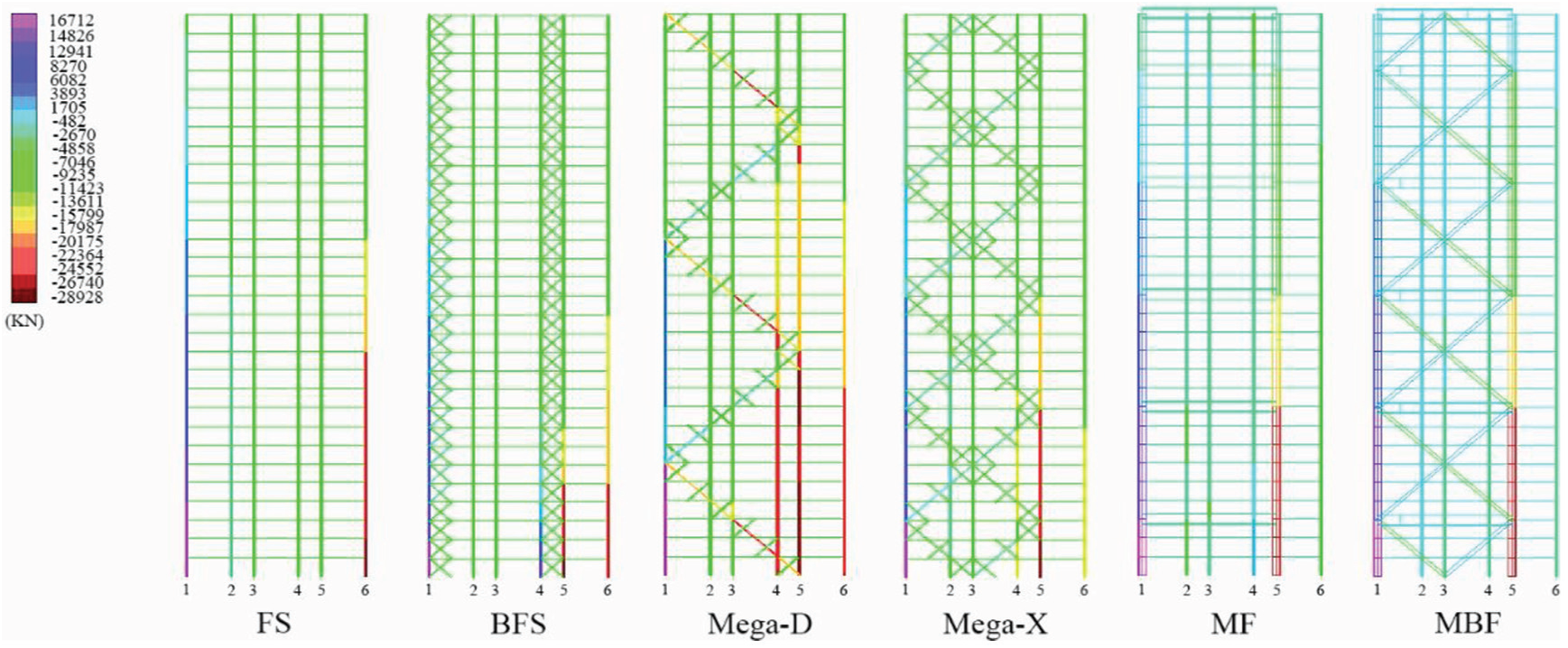
Axial force distribution diagrams for models with different lateral resistant systems.

Axial forces of bottom columns of the six models.
Figure 4 shows the interstory drift diagram of BFS and mega-D and mega-X structures. It can be seen that the quasi-megastructure layout schemes have great promotion in lateral stiffness of structures with little material consumption increase. However, the interstory stiffness distribution of the structures with the mega-X or mega-D layout scheme is extremely irregular, which needs to be controlled before further research for application. Thus, a simplified interstory lateral stiffness calculation method is put forward to investigate the relationship of internal force and deformation of quasi-megastructures.

Interstory drift ratio diagrams of BFS and mega-D and mega-X structures.
Calculation assumptions for quasi-megastructure
Composition of structural interstory drift
For high-rise residential quasi-megastructure, when the interstory drift of any target story is being calculated, the whole structure can be divided into four deformation regions according to their respective contribution to interstory drift of the target story (Figure 5(a)). The four deformation regions are upper stories, target story, shear-lagged interaction region, and base rotation region. The upper stories include all the stories above the target story. Stories in this region have limited contribution to the interstory drift of the target story. The shear-lagged interaction region is generally several adjacent stories under the target story. Due to the existence of the shear-lag effect, which is substantially induced by axial deformation of columns, the columns in this region should be modeled as elastic supports of the target story. Then its amplification to the shearing deformation of the target story must be considered. It is assumed that the shear-lagged interaction region includes m stories under the target story, which is the number of stories within a quasi-megastructural module. Then all the remaining stories under the shear-lagged interaction region only contribute to the rigid body rotation of the target story which is leaded by the axial elongation and shortening of columns. They constitute the base rotation region, which acts like a rotatable base of the structure (Figure 5(b)). The interstory drift of the target story can be evaluated by summing up the contribution of all the four regions.
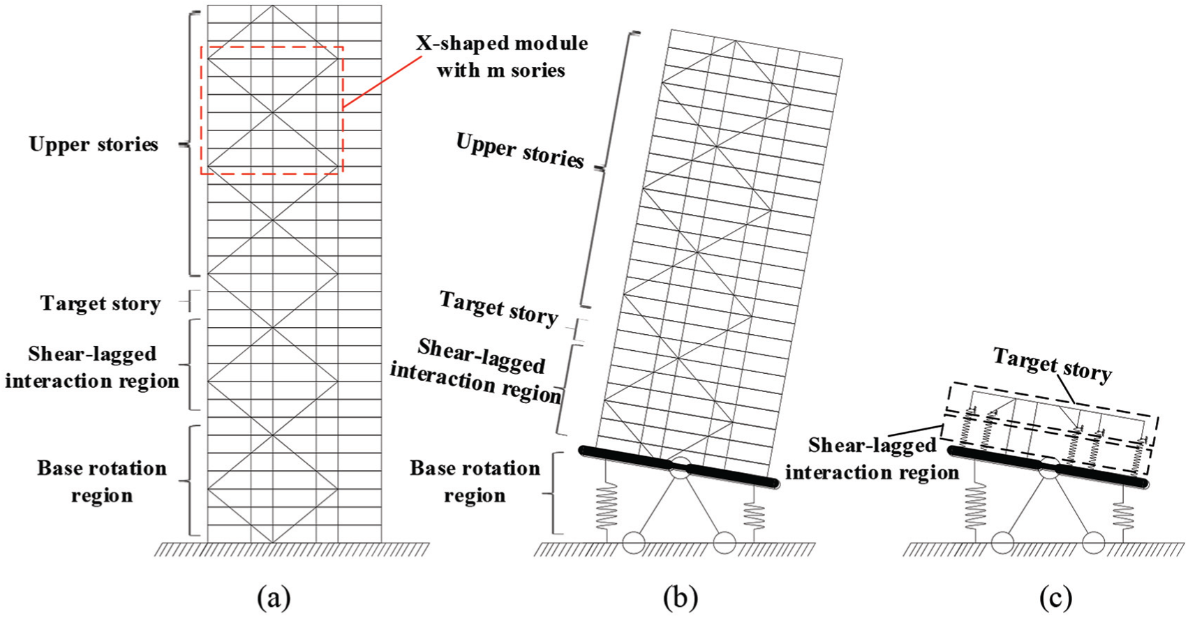
(a) Region of structural deformation, (b) base rotation model, and (c) single-story shear model.
Assumptions
In order to simplify the calculation of the interstory drift of the target story, several calculation assumptions are put forward as follows.
Assumption 1
The contribution of upper stories can be neglected.
For high-rise structures, the interstory drifts include destructive and nondestructive drift. The destructive drift is caused by the deformation of members within a target story. It is dependent on the shearing force of every story. The nondestructive drift is caused by the overall rotation of the target story, which results mainly from the axial deformation of columns in the lower stories (Deng et al., 2008; Wei, 2010). The contribution of upper stories is very limited and therefore can be neglected.
Assumption 2
Interstory drift consists of contributions of rigid body rotation and shearing deformation.
The interstory drift of the target story

where
Assumption 3
Contribution of internal force components out of the major force path (Figure 6) of the virtual forces corresponding to the target interstory drift can be neglected.
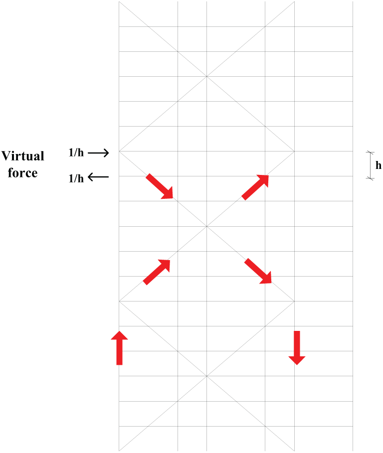
Major force path of the virtual forces corresponding to the target interstory drift ratio.
Simplification of the cross braces of BRSPSW
For the quasi-megastructure with the mega-X brace layout scheme (Figure 7(a)), the layout of each pair of cross braces arranged in different stories leads to several mega-X modules within six stories. As a result, the structural lateral force mainly transfers along the mega-X brace path, which is the major force path of this structure. The axial forces of two brace bars in each pair of cross braces have a large difference. It means that the axial forces of brace bars in the major force path are larger than those of brace bars that are not in the major force path. Assuming that the brace bars that are not in the major force path are zero-force members, then the original mega-X brace layout model can be simplified into diagonal braces lateral resistant system (Figure 7(b)). In comparison, such simplification is not applicable for the BFS, as both of the cross braces are located in the major force path there.
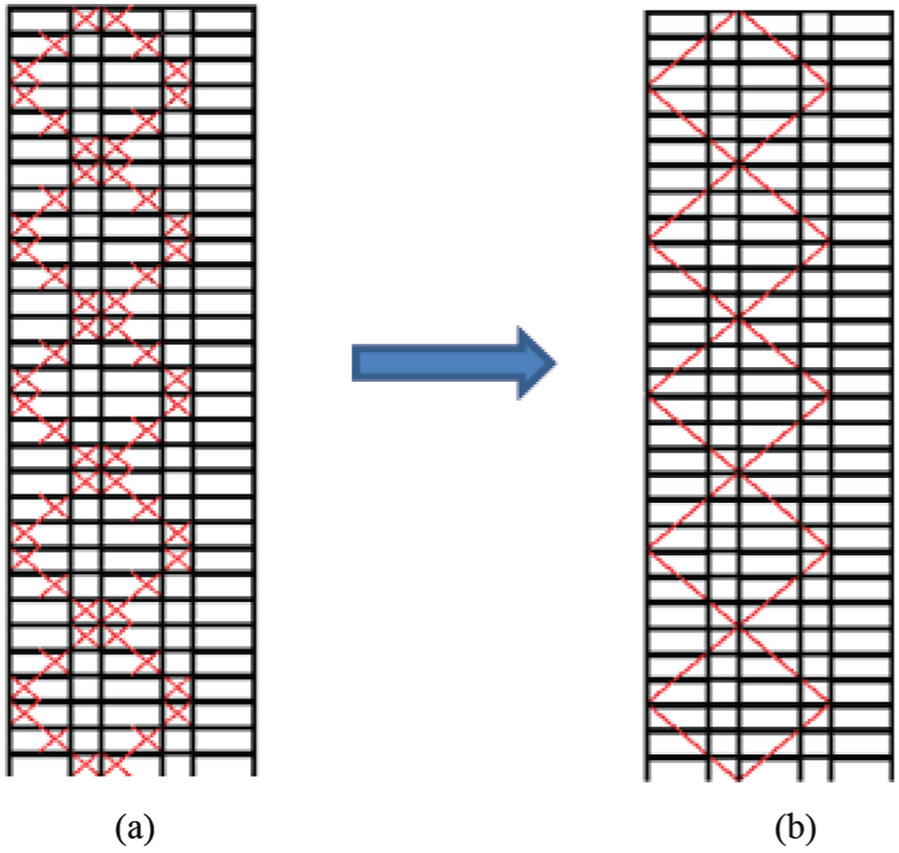
Model simplification for cross braces: (a) presimplified model, (b) simplified model.
Simplification of the single-story shear model of the target story
When calculating
Taking an ith story in Figure 8 as an example, the joints on the ith floor are all without any restraint;
The joints on the (i – 1)th floor are all restrained in the horizontal direction;
The vertical direction of each joint in the (i – 1)th floor can be generally assigned with an elastic support, the stiffness of which can be assumed as the axial stiffness of the corresponding column in the shear-lagged interaction region;
According to Assumption 3, the elastic supports at the neighborhood of the rotational neutral axis of the story need to be replaced with fixed supports, as the axial deformation of columns below is negligible.
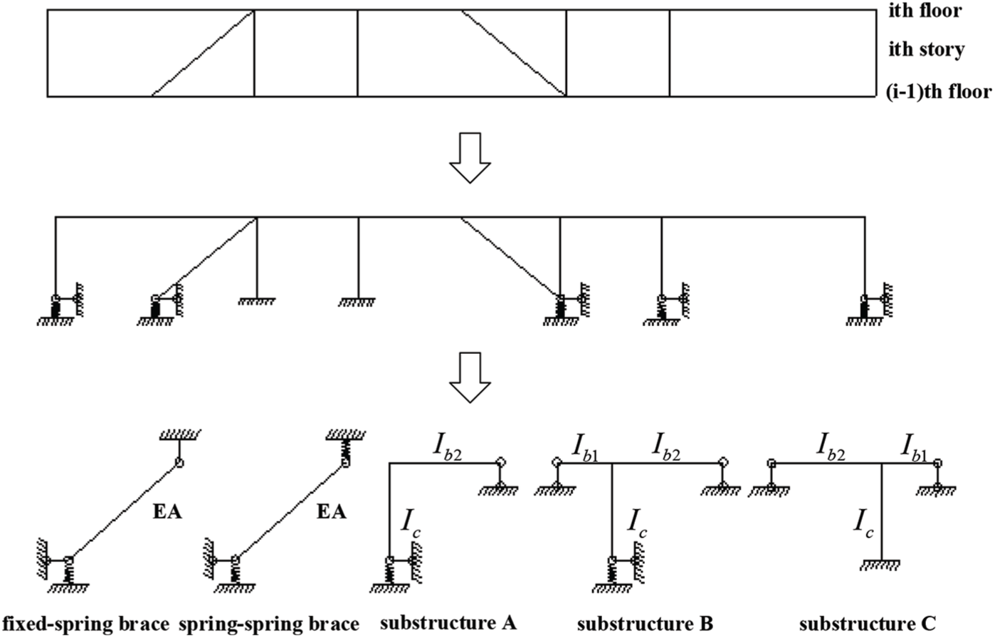
The simplified shear model and typical substructures of a target story.
The simplified shear model of a target story with considering boundary conditions is shown in Figure 8. All the beam–column joints in frame are assumed to be fully rigid in the model. The problem of panel zones is not considered, because it can be avoided by constructional measures. The single-story shear model can be further simplified as a parallel system composed of substructures, by the following assumption:
The point of inflection of each beam segment is located at its mid-span;
The support at the middle of a beam to a diagonal brace can be modeled as a vertical elastic support with the same vertical stiffness.
In the next section, the drift formula will be explicitly derived according to the above assumption.
Deduction of the interstory drift formula
Calculation of drift contributed by rigid body rotation,
For any story i in the base rotation region, its rotational angle contributed to rigid body rotation of the target story is

where
Because the rigid body rotation of the target story is caused by the axial deformation of columns in the base rotation region, the bending stiffness

where
When the target story is lower than the (m + 2)th story, all stories lower than the target story belong to the shear-lagged interaction region, and there is no base rotation region. Hence, the interstory drift contributed by rigid body rotation is considered starting from the (m + 2)th story. The interstory drift of the target story contributed by rigid body rotation is equal to the sum of rotational drift caused by all stories in the base rotation region

where t is the story number of the target story.
Calculation of drift contributed by shearing deformation,
As mentioned before, a single-story shear model can be simplified as a parallel system of substructures. Hence, its lateral shearing stiffness can be obtained as the sum of lateral stiffness of all substructures. There are two types of substructures, that is, brace substructures and frame substructures. Lateral stiffness of each type is calculated as follows.
Calculation of lateral stiffness of brace substructure
There are three situations according to vertical support constraints at two brace ends. They are fixed–fixed case, fixed–spring case, and spring–spring case as shown in Figure 8.
In the fixed–fixed case, its lateral stiffness formula is

where
In the fixed–spring case, its lateral stiffness formula is

where
Elastic supports may correspond to two situations. One is that the diagonal brace is supported at a beam–column joint. The elastic support considers the axial deformation of columns in the shear-lagged region. Thus,
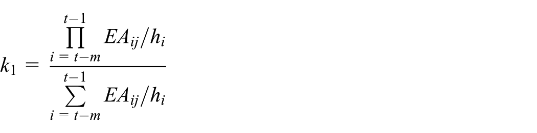
Another one is that the diagonal brace is supported on the midpoint of a beam. The elastic support considers the vertical supporting displacement of the beam. In this situation,

where l is the span of the supporting beam.
In the spring–spring case, the stiffness of the two springs are

Calculation of lateral stiffness of frame substructures
When isolating frame substructures, the inflection point of each beam is assumed to be located at the mid-span. Hence, the multi-span frame can be divided into three types of frame substructures (Figure 8).
For the frame substructure A, its lateral stiffness is

where

For the frame substructure B, its lateral stiffness is

where

For the frame substructure C, its lateral stiffness is

where

Single-story shear models for typical stories
Three typical stories with different brace layouts from the structure model in Figure 5, such as the 10th to the 12th story, are selected. With the assumptions in section 3.4, their single-story shear models can be obtained, respectively.
For the 11th and 12th stories, the lateral shearing stiffness of each story can be obtained by summing up the lateral stiffness of all its substructures as follows
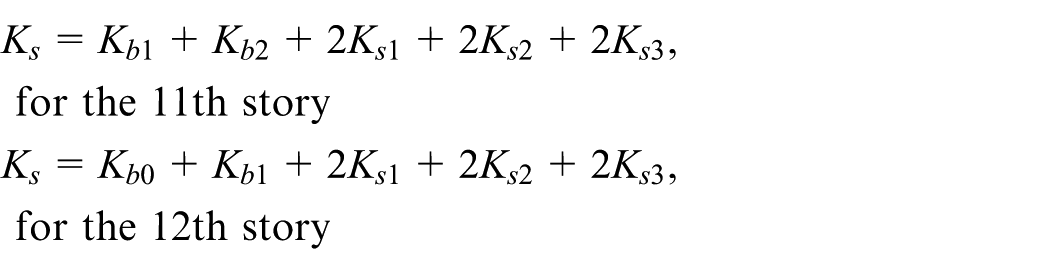
As for the 10th story, the effect of localized rotation needs to be considered when there appears a localized truss system with elastic supports, where structural internal forces pass by means of axial force along the columns under the truss. So axial forces in these columns are larger than those in the other columns, probably leading to the amplification of interstory drift of the target story. The localized truss system should be taken as an integral substructure, instead of a combination of smaller substructures. Therefore, two bottom springs have axial deformation due to overturning moment and then make the localized truss system rotate. The total flexibility of this truss system is

where L is the total height of the upper stories corresponding to the target story. So the lateral shearing stiffness of the 10th story is

Total interstory drift of the target story
According to the interstory drift formula in section 3.2, the total interstory drift of the target story is

where V is the shearing force of the target story.
For other similar quasi-megastructures with different lateral component layouts, their own interstory drift formula can be deduced with the proposed assumptions and the simplification method above.
Validation of the calculation model
To verify the validity of the proposed simplified model, a planar quasi-megastructure example similar to the mega-X layout scheme shown in Figure 7(b) is established. Except the diagonal brace instead of cross brace, all members and dimensions are the same.
This structure is composed of I-shaped steel columns, H-shaped steel beams, and the braces with box section. Size of each member is shown in Table 1. In order to simplify the model, the same size is chosen for the same type of members in different stories. Short beams and long beams are, respectively, arranged on the short span and long span of the planar model. A lateral concentrated load of 5000 KN is applied at the top of the structure. Comparison of interstory drift diagrams derived from the simplified model and numerical simulation results is shown in Figure 9. It can be seen that the result from the simplified model coincides well with that from the numerical simulation. The result of several stories at bottom has a certain deviation. The average deviation of all stories is 8.74%.
Member size of models in this article.
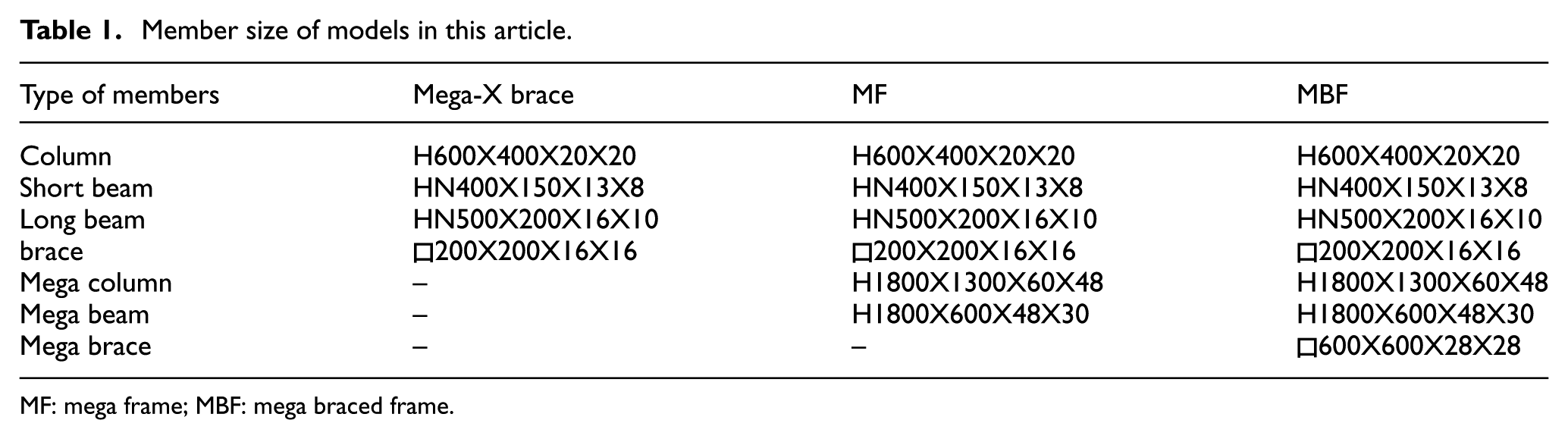
MF: mega frame; MBF: mega braced frame.
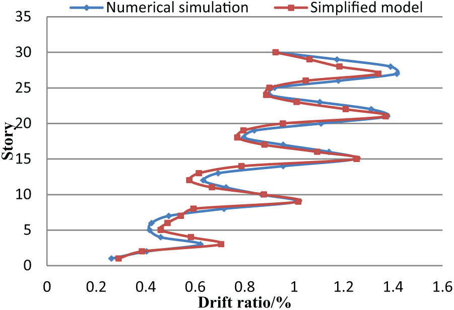
Interstory drift ratio diagram of the example quasi-megastructure.
Cause of vertical stiffness irregularity in quasi-megastructure
Analysis of interstory drift proportion
According to the above simplified model, lateral drift consists of three parts, namely, rigid body rotation, pure shearing drift, and additional drift due to the shear-lag effect. The pure shearing drift can be calculated by assuming that all bottom constraints of the target story are fixed end. The additional drift can be calculated as the drift difference between the results from two single-story models with elastic supports and with fixed supports. The interstory drift formula deduced previously is used to investigate the relationship of the constitution of these three types of drift, as shown in Figure 10.
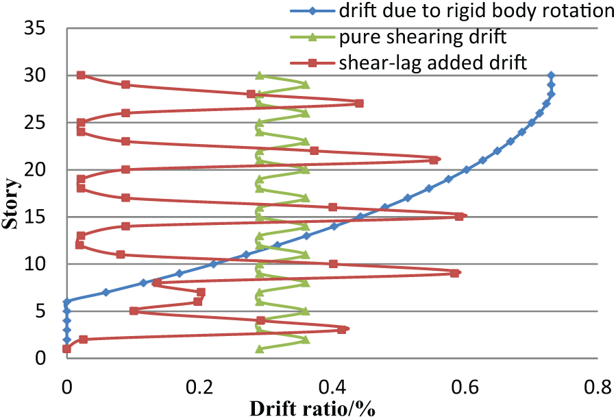
Interstory drift ratio proportion of quasi-megastructure.
It can be seen that the irregular distribution of interstory drift is mainly caused by shear-lag added drift. Therefore, we can infer that various layouts of lateral components lead to great changes of shear-lag added drift between different stories within the corresponding module. Comparatively, interstory drift induced by rigid body rotation increases smoothly over the height, while pure shearing drift is essentially unchanged in each story. Minor change in the pure shearing drift every third stories is because the upper ends of some braces are supported at the beam mid-span instead of beam–column joint.
Analysis of the structural stiffness ratio
In this subsection, the concept of structural stiffness ratio is used to examine the degree of vertical stiffness irregularity of the previous example quasi-megastructure. According to Chinese code Technical specification for concrete structures of tall building, a structure suffers from vertical stiffness irregularity if the stiffness ratio between the target story and its adjacent upper story is less than 0.7, or the stiffness ratio between the target story and its adjacent three upper stories is smaller than 0.8. The stiffness mentioned in this code is interstory lateral stiffness which equals interstory shearing force by interstory drift. The stiffness ratios of the example calculated by numerical simulation are shown in Figure 11, showing that the vertical stiffness distribution is irregular.
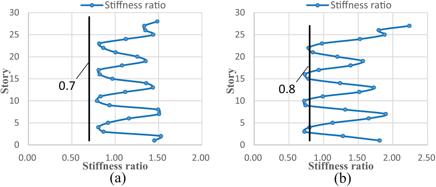
Stiffness ratios of the example model: (a) stiffness ratios of the adjacent upper story and (b) stiffness ratios of the adjacent three upper stories.
Regarding the 10th to 15th stories as a single mega module, Table 2 shows the drift percentage of every story in the module. The shear-lag added drifts of the 10th and 15th stories achieve much larger percentage than the other stories. It leads to the large interstory drift of these two stories. According to the brace layout, it can be concluded that the localized truss system leads to great additional drift in these two stories. This effect has been considered in the proposed formula in section “Assumptions.” Compared with the stiffness ratio, it can be found that the 10th and 15th stories are just the stories with the lowest stiffness ratios. It means that a large shear-lag added drift leads to the formation of a “weak story.”
Drift percentage and the stiffness ratio of every story in the single mega module.

The supplemental quasi-mega mechanism to reduce vertical stiffness irregularity
Effect of the supplemental quasi-mega mechanism
In order to eliminate the vertical stiffness irregularity of the example quasi-megastructure, two stiffened quasi-mega layout schemes with the supplemental quasi-mega mechanism were conceived, as shown in Figure 12.

Stiffened quasi-megastructure layout scheme: (a) Plan SI and (b) Plan SE.
BRSPSW is infilled within a short beam span continuously from the ground to the top, forming a quasi-mega cantilever wall. Although locations of the quasi-mega wall in the two layouts in Figure 12 are symmetric to each other with respect to moment frame only, the quasi-mega wall is located near and far from the overturning neutral axis of the quasi-megastructure in Plan SI and Plan SE, respectively. It means that Plan SI stiffens inner columns in the mega module, and Plan SE stiffens external columns in the mega module.
Interstory drift diagrams of the two stiffened schemes with the same member sections and loading conditions of the original scheme are shown in Figure 13(a). It can be seen that both schemes are effective in reducing interstory stiffness irregularity and Plan SI is the more effective one.

Interstory drift ratio diagram of the stiffened scheme under different loads: (a) lateral concentrated load and (b) seismic load.
The reduction of stiffness irregularity is further examined in respect of seismic responses. The design earthquake group is the first group and the intensity is 7 degrees (0.1 g), with site classification of the second type, according to the Chinese seismic design code GB 5001. The results shown in Figure 13(b) indicate that the seismic interstory drifts are also greatly smoothened in the stiffened schemes.
Analysis of the interstory drift proportion of the stiffened schemes
Based upon the proposed simplified method in section “The lateral resistant mechanism of quasi-megastructure,” similar formula can be deduced for the stiffened schemes. It is noteworthy that the cross braces are set from the bottom to the top between the central columns in plan SI. It makes the central columns become vertical force transfer paths for the supplemental braces. It means that their internal force and deformation cannot be neglected. So the central columns should be considered as elastic support for any target story above.
Comparison of the results of interstory drifts by both numerical simulation and the simplified model is presented in Figure 14, showing satisfactory agreement.

Interstory drift ratio diagram of the stiffened scheme calculated by formula: (a) Plan SI and (b) Plan SE.
Based on the simplified method, the components of interstory drift including drift due to rigid body rotation, pure shearing drift, and shear-lag added drift are plotted for both the schemes in Figure 15.

Deformation diagram of each part of stiffened structure: (a) Plan SI and (b) Plan SE.
Compared with Figure 10, it can be seen that the distribution of shear-lag added drift in Plan SI has become quite smooth, while the improvement of Plan SE is not so effective.
Analysis of the structural efficiency of different schemes
The stiffened schemes can be further compared with the original scheme by means of structural efficiency,

where Δ cs is the horizontal roof displacement caused by axial deformation of the members and Δ t is the total horizontal roof displacement.
In a high-rise structure under horizontal loading, a larger

where Δ ra is the sum of rigid body rotation–induced drifts of all stories and Δ sa is the sum of shear-lag added drift of all stories.
With the
Structural efficiency of the three different layout schemes.
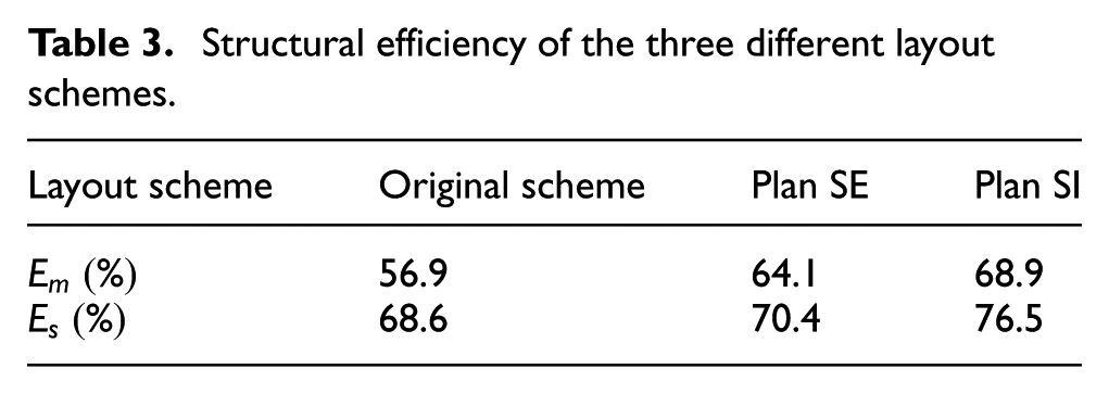
As the evaluation of axial deformation contribution to the total horizontal roof displacement is not a straightforward task for practical projects, a megastructure efficiency Em is defined as follows

Em can be used not only for quasi-megastructures, but also for megastructures by the following simple approach. With the axial deformation of exterior major columns in each story provided by any software of structural analysis, the rigid body rotation angle caused by this story can be calculated. Then the sum of rigid body rotation–induced drifts of all stories, Δ ra , can be obtained easily.
In Table 3, it can be seen that Em has the same trend of variation among the schemes as Es does, as Δ ra is the main factor controlling structural efficiency.
Comparison of the stiffness ratio between quasi-megastructure and megastructure
In this section, a mega frame (MF in Figure 2) and a mega braced frame (MBF in Figure 2) are conceived based upon the same frame structure in the original scheme. The member sizes of Plan MF are shown in Table 1.
The method for checking vertical stiffness irregularity in Technical specification for concrete structures of tall building is used to calculate the ratio of stiffness of the target story both with that of the adjacent upper story and with the average stiffness of the adjacent three upper stories.
Comparing the stiffness ratio diagrams of Plan MF in Figure 16 with those in Figure 11, it can be found that Plan MF behaves quite close to the original scheme. It means that although the original quasi-megastructure layout scheme has quasi-mega braces, it is closer to mega frame structure in respect of the deformation mechanism.
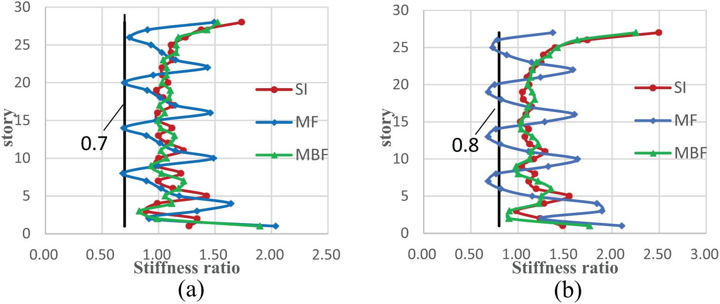
Stiffness ratios of Plans SI, MF, and MBF: (a) stiffness ratios of the adjacent upper story and (b) stiffness ratios of the adjacent three upper stories.
Plan MBF is conceived based upon Plan MF by supplementing mega braces with the section of box 600 × 600 × 28 mm3. Comparing the stiffness ratio diagrams of Plan MBF with those of Plan SI in Figure 16, it can be observed that Plan SI behaves quite close to Plan MBF. And the megastructure efficiency Em of Plan MBF is 72.8%, which is close to Plan SI.
Conclusion
The main research results and conclusions of this article include the following points:
The concept of quasi-megastructure based on mega-X layout pattern is put forward, which is applicable for high-rise residential projects. Compared with megastructure, it avoids the drawback in large architecture space occupancy due to mega members in megastructures.
Unlike the megastructures that are dominated by their primary structures, the quasi-megastructures mainly realize a synergistic mechanism between the frame structure and quasi-mega braces.
With three assumptions, a simplified method for the evaluation of interstory drift of high-rise quasi-megastructure was proposed. The formula of interstory drift can be deduced by means of the proposed method for any specific layout scheme of quasi-megastructure. The average deviation of this model is within 10%.
The interstory drift of a target story mainly consists of drift due to rigid body rotation, pure shearing drift, and shear-lag added drift. Various layouts of lateral components lead to great changes of shear-lag added drift in different stories within the corresponding module. It is the main factor that causes the stiffness irregularity of quasi-megastructure.
For the original quasi-megastructure layout scheme in this article, stiffened schemes were proposed to solve the problem of stiffness irregularity, which has a great effect on reducing interstory stiffness irregularity and enhancing the structural efficiency Em, about 12% improvement, with acceptable material consumption.
In spite of its quasi-mega braces, the original quasi-megastructure layout scheme is closer to mega frame structure in respect of the deformation mechanism. Meanwhile, with proper improvement, the stiffened scheme, Plan SI, behaves quite close to mega brace frame structure, in respect of both deformation mechanism and structural efficiency.
Footnotes
Declaration of Conflicting Interests
The author(s) declared no potential conflicts of interest with respect to the research, authorship, and/or publication of this article.
Funding
The author(s) disclosed receipt of the following financial support for the research, authorship, and/or publication of this article: This study was financially supported by the National Key Research and Development Program of China (Project No. 2016YFC0701203), which is greatly acknowledged.
