
Abstract
This article presents an experimental and theoretical investigation on the shear behavior of fiber-reinforced ultra-high-performance concrete beams reinforced with high-strength steel. The test parameters included the fiber volume fraction, fiber type, and stirrup ratio. The test results indicate that the shear failure in ultra-high-performance concrete beams is not brittle and catastrophic but has ductility characteristics. A moderate quantity of stirrups can significantly improve the shear behavior of ultra-high-performance concrete beams, as reflected in the thorough propagation of cracks in both shear span and pure bending zone. The depth of the compression zone considering concrete tension was derived based on the deformation compatibility and force equilibrium equations for both serviceability limit state and ultimate limit state. The comparison of the proposed method and classical beam theory shows that the concrete tension should not be neglected in the serviceability limit state analysis. After cracking, the concrete tension can be neglected for simplicity when the beam is heavily reinforced and should be considered when the beam is lightly reinforced. Then, a shear strength model was established based on Rankine’s failure criteria, the truss model, and Association Francaise de Génie Civil-Sétra. Finally, the proposed shear strength equation was verified by the test results and compared with other shear strength equations.
Keywords
Introduction
Ultra-high-performance concrete (UHPC) is a recently developed advanced construction material that exhibits superior compressive and tensile strengths, toughness, and bond performance, along with exceptional durability (Qi et al., 2018b; Richard and Cheyrezy, 1995; Yoo et al., 2014). The superior performance is attributed to the high packing density and inclusion of randomly distributed high-strength steel fibers, which significantly improves the strength and ductility of the matrix (Graybeal, 2007; Qi et al., 2016a, 2018a). Such advanced mechanical properties enable the construction of light-weight, thin-web, and long-span structures that reduce the life-cycle cost (Qi et al., 2016b; Wang et al., 2019).
To adequately take advantage of the superior mechanical properties of UHPC, high-strength steel (HSS) should be cooperatively used instead of ordinary-strength steel bars. Direct tension test results indicate that the ultimate tensile strain of UHPC can easily exceed at least 0.005 (Graybeal and Baby, 2013; Pyo et al., 2015; Wille et al., 2014). Based on the deformation compatibility condition, the stress in the tension reinforcement can reach 0.005 × 200,000 = 1000 MPa in the ultimate state. Consequently, the material performance advantages of HSS and UHPC can be fully developed by jointly using the two materials. However, the design attribute of shear due to the thin web must be addressed in these HSS–UHPC beams.
Lim and Hong have demonstrated that if the rectangular beam contains UHPC with a fiber volume fraction of 1.5%, shear reinforcement need not be provided, and the spacing limit of 0.75 d is allowable for UHPC beams based on the test results (Lim and Hong, 2016). Ferrier et al. (2016) proposed a new type of beam made of UHPC and fiber-reinforced polymer (FRP) rebar and examined the shear behavior of the proposed beams based on shear tests in six FRP–UHPC beams. The test results indicated that the beam exhibits the typical reinforced concrete beam behavior in terms of concrete cracking and shear failure, which is nearly flexural failure. Xia et al. (2011, 2015) demonstrated that the shear failure of UHPC beams exhibits a ductile characteristic with higher post-crack shear resistance, which they recommended as an acceptable failure mode because of the fiber bridging effect across the cracks and the secondary load transfer mechanism between the concrete and rebar. Based on test results, Baby et al. (2014) demonstrated that the addition of shear reinforcements and UHPC effectively contributed to the shear strength. Voo et al. (2010) reported shear test results on eight UHPC beams and noted that a significant distribution of shear cracking occurred through the web before the dominant failure crack formed. Yang et al. (2012) indicated that the instability of the arch mechanism decreased the load increments up to the peak load after the initial cracking for the beams with larger shear span-to-depth ratios. Hegger and Bertram (2008) showed that when the fiber volume fraction increased, the failure became increasingly ductile according to test observations. Thus, the shear behavior of UHPC beams is not adequately understood, especially in HSS–UHPC beams. Therefore, more knowledge is necessary for the popularization and application of new HSS–UHPC beams in engineering practice.
In this article, an experimental investigation on the shear behavior of HSS–UHPC beams is first presented. Seven beams were prepared and tested to fail in shear with different steel fibers and stirrups. A theoretical model was developed to predict the shear strength of the test beams. The depth of the compression zone concrete was derived considering the concrete tension, and the shear contribution of concrete was obtained using Rankine’s failure criteria and the strain and stress distribution of the compression zone. Finally, the proposed model was verified by the test results and compared with other shear strength models.
Experimental investigation
Variables and specimens
The main variables studied in the experimental program were the type and quantity of fibers and the stirrup ratio. All seven beams with a T cross-section had identical geometric dimensions and a shear span-to-depth ratio of 3.17. Due to the insignificant size effect in fiber-reinforced concrete beams, small-scale beams were chosen for this experiment (Li et al., 1998). The total length of the test beams was 1300 mm, and the net length was 1140 mm. The depth of the section was 140 mm (effective depth of 114 mm), and the thickness of the web was 40 mm. The top flange was 35 mm high and 120 mm wide. Figure 1 and Table 1 show the details of the test beams.
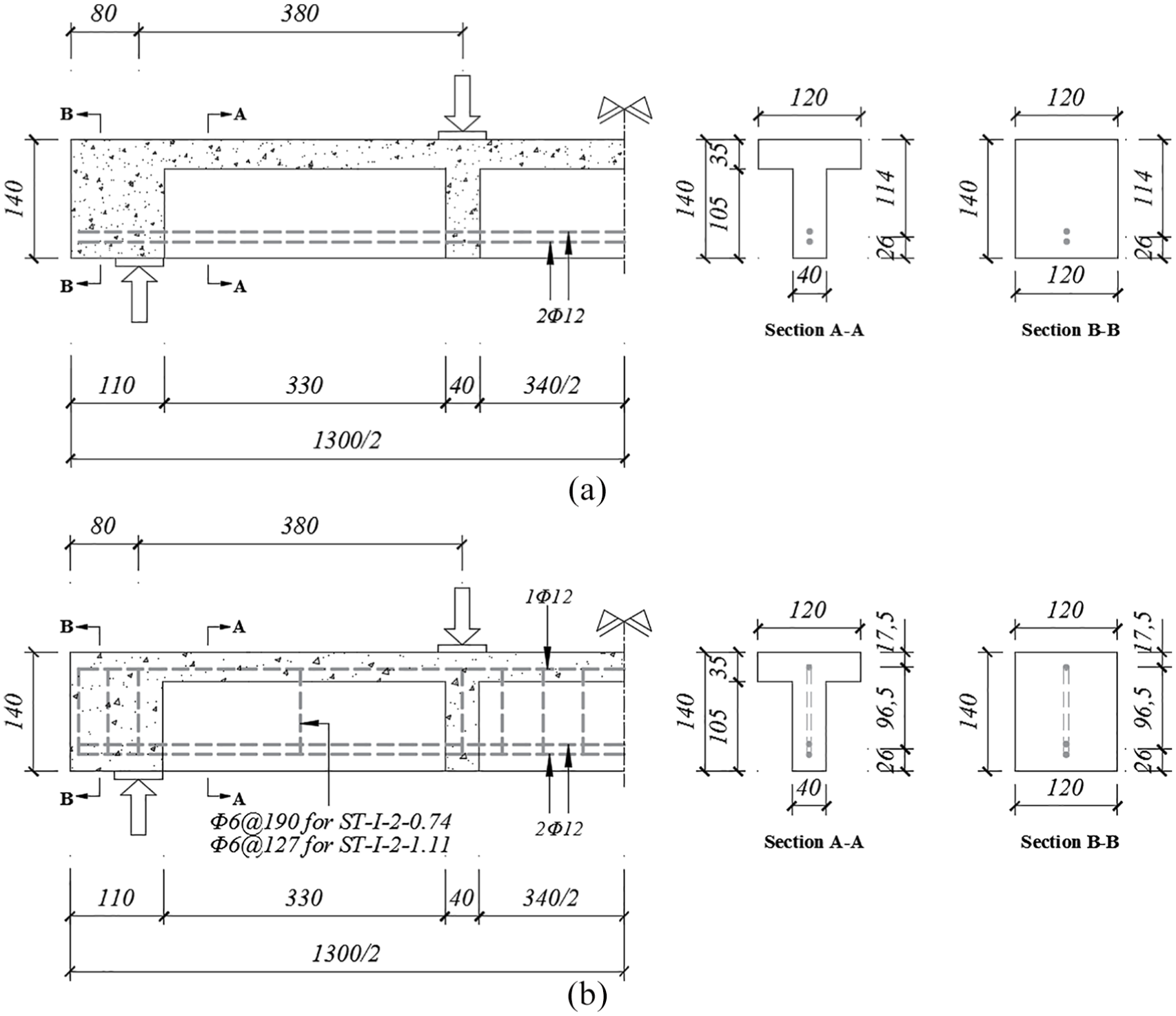
Dimensions and cross-section of the test beams (unit: mm). (a) specimen without stirrups and (b) specimen with stirrups.
Parameters of the test beams.
a/d: shear span-to-depth ratio; ρs: longitudinal reinforcement ratio; ρf: fiber volume fraction; ρv: stirrups ratio; s: space of stirrups.
The beam ID was designated as “ST–fiber type–fiber volume fraction–stirrup ratio.” For example, the benchmark beam ST-I-2-0 indicates that type I steel fiber with a volume fraction of 2% is used, but no stirrups are provided, and ST represents the shear test.
Test setup and instrumentation
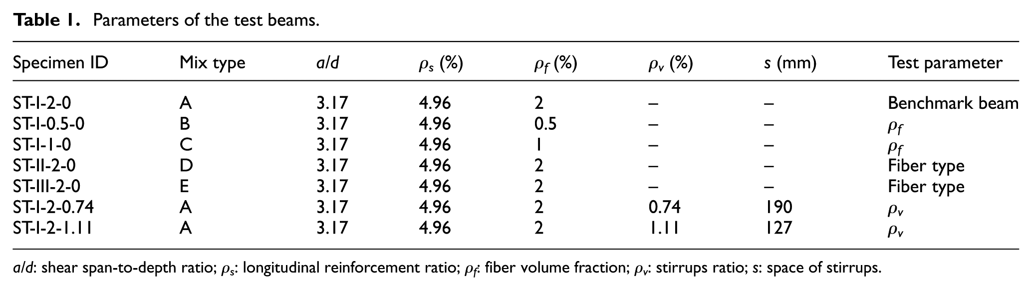
All beams were tested in a four-point bending configuration (Figure 2). The shear span-to-depth ratio was set to 3.17 to avoid significant arching action, where the load is directly transferred from the load point to the support. During the test, the load was applied in 5 kN increments per minute before cracking and changed into 3 kN increments per minute after cracking to failure. The test was terminated when shear failure occurred with a sharp decrease in applied load. At each loading stage, the propagation of new cracks was identified and marked, and the deflections at different sections were measured. Strain gauges were attached to the longitudinal reinforcements, stirrups, and concrete surface to measure the strains during testing.
Test setup.
Mixture proportions and material properties
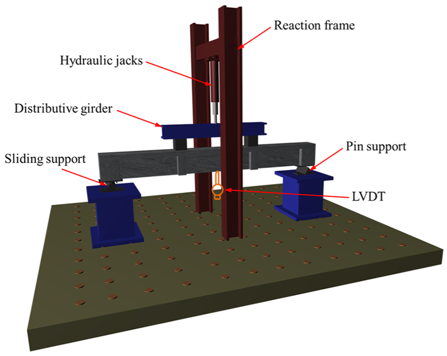
Table 2 provides the details of the UHPC mix proportions used in the study. The cement and silica fume in this project are commonly commercially available in China. River sand, instead of quartz sand, was used to reduce the cost of the UHPC. The specific gravity and fineness modulus of the river sand were 2.66 g/cm3 and 2.8, respectively. A self-developed high active admixture was introduced into the mixture to improve the viscosity and mechanical performance of the UHPC. The density, specific surface area, and activity index of the high active admixture at 28 days were 2.56 g/cm3, 1230 m2/kg, and 115%, respectively. All mixtures had a water-to-binder ratio of 0.15.
UHPC mix proportions.
UHPC: ultra-high-performance concrete; W/B: water-to-binder ratio.
Material quantities in kg/m3 of UHPC.
In total, 15 cubes from five mixing batches were tested to obtain the compressive strength of the UHPC. The cubes were sized at 100 mm. In total, 10 prisms with dimensions of 100 mm × 100 mm × 300 mm and 15 prisms with dimensions of 100 mm × 100 mm × 500 mm were cast to obtain the elasticity modulus and tensile strength of UHPC. The properties of the designed UHPC mixture are presented in Table 3. The elastic modulus of the UHPC is about 1.5 times as much as that of normal-strength concrete.
Properties of UHPC.
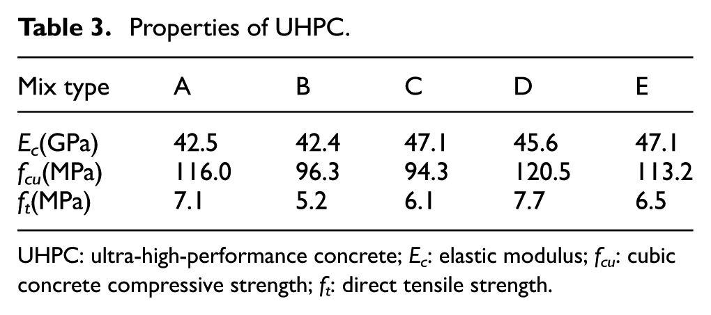
UHPC: ultra-high-performance concrete; Ec: elastic modulus; fcu: cubic concrete compressive strength; ft: direct tensile strength.
The dimensions and properties of the steel fibers in this project are shown in Table 4. Three types of straight steel fibers with different aspect ratios were involved. The deformed longitudinal reinforcement and stirrups in the study were 12 and 6 mm in diameter and 760.9 and 417.2 MPa in yielding strength, respectively.
Dimensions and properties of steel fibers.
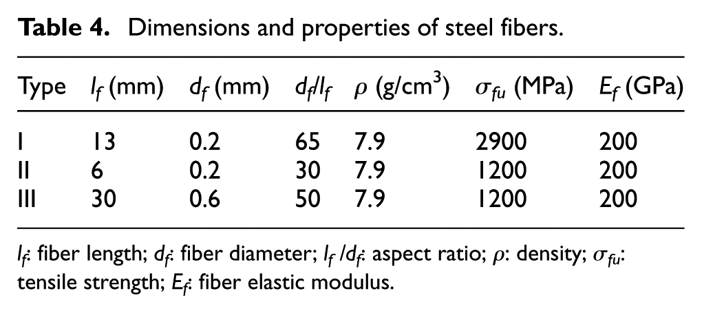
lf: fiber length; df: fiber diameter; lf /df: aspect ratio; ρ: density; σfu: tensile strength; Ef: fiber elastic modulus.
Test results and discussions
General behavior
Web shear crack, instead of flexural shear crack, first appeared in the shear span and subsequently propagated toward the loading point and the support (Figure 3). Due to the relatively large shear span-to-depth ratio, the applied load cannot be directly transferred from the loading point to the support, which results in two longitudinal tearing cracks at the end of the diagonal shear crack: one of them propagated along the bottom of the top flange, and the other one propagated along the longitudinal reinforcement (Figure 3). When the load approached the ultimate load, the continuously increased applied load was resisted by the opening of the critical diagonal crack and the increment in beam deflection. Finally, diagonal tension failure occurred in the beams without stirrups, whereas the combined failure of shear and flexure occurred in the beams with stirrups. The longitudinal reinforcement did not reach the yield strength at failure. Unlike the brittle shear failure of normal-strength reinforced concrete beams, the shear failure in the UHPC beams was not brittle and catastrophic but displayed ductility characteristics. This phenomenon may be attributed to the fiber bridging effect mechanism and not a sudden extensive crushing of the shear compression zone concrete. The experimental results are summarized in Table 5.
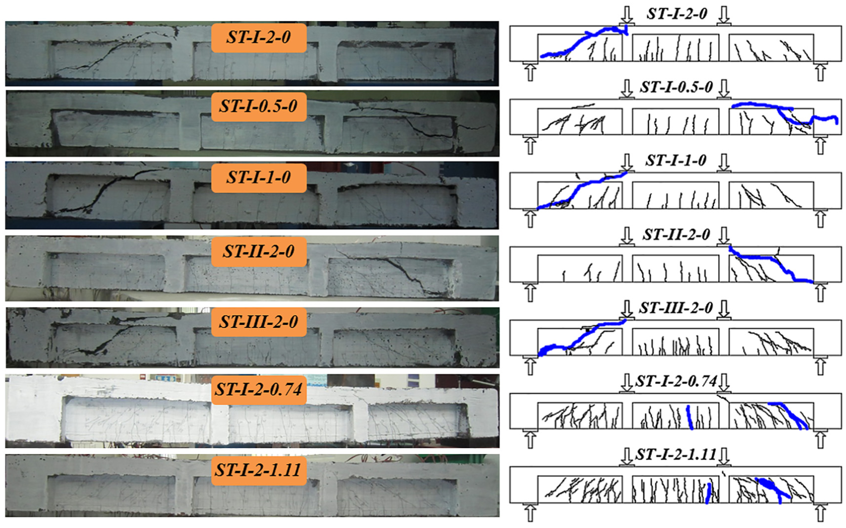
Crack patterns of the test beams at failure.
Experimental results.
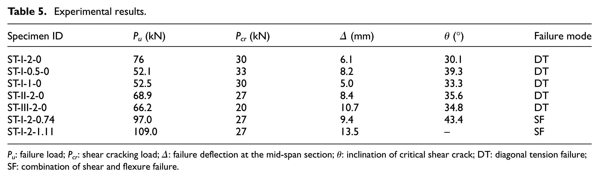
Pu: failure load; Pcr: shear cracking load; Δ: failure deflection at the mid-span section; θ: inclination of critical shear crack; DT: diagonal tension failure; SF: combination of shear and flexure failure.
Figure 3 presents the crack patterns of the test beams at failure. Different from conventional reinforced concrete beams, many short fine diagonal shear cracks appeared and propagated near the critical diagonal shear crack with small spacings, which significantly improves the shear behavior of the test beams. It can be observed that reinforcing with a moderate quantity of stirrups can significantly improve the shear behavior of UHPC beams, which is reflected in the thorough propagation of cracks in both shear span and pure bending zone. In other words, this phenomenon indicates an efficient utilization of the randomly dispersed fibers for the crack resistance. Consequently, although fibers can be considered dispersed tiny reinforcements in a beam, it is recommended that a moderate quantity of stirrups should be contained in a UHPC beam to attain a superior structural behavior.
Figure 4 shows a typical set of deflection curves of benchmark beam ST-I-2-0. In general, the symmetrical section attained approximately equivalent deflection in the early loading process. When the load approached the ultimate load, only the critical diagonal shear crack quickly propagated in width compared with other cracks, which caused a relatively larger deflection in the loading point section adjacent to the critical diagonal crack (point A) than the loading point section away from the critical diagonal crack (point B).
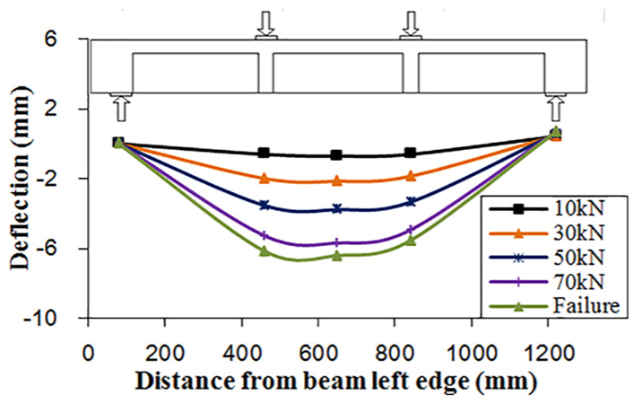
Distribution of the deflection along the length of benchmark beam ST-I-2-0.
Effect of fiber volume fraction
The fiber volume fraction significantly affects the shear behavior of UHPC beams regarding the shear strength and beam stiffness, as shown in Figure 5. Concerning beams ST-I-0.5-0 (ρf = 0.5%) and ST-I-1-0 (ρf = 1%), it is interesting that more fibers can significantly increase the beam stiffness but cannot improve the shear strength. In contrast, for beams ST-I-1-0 (ρf = 1%) and ST-I-2-0 (ρf = 2%), more fibers can significantly enhance the shear strength but cannot significantly improve the beam stiffness. This phenomenon can be explained as follows. At a low fiber volume fraction, the shear strength contribution of steel fibers is not significant, but the beam stiffness increment induced by steel fibers is apparent. At a high fiber volume fraction, the beam stiffness is not sensitive to the increase in fiber volume fraction, but the shear strength contribution of steel fibers becomes significant. However, it is believed that both shear strength and beam stiffness can be significantly increased when the fiber volume fraction reaches 2%. Figure 5(b) indicates that the inclination of critical diagonal shear crack decreases when the fiber volume fraction increases, because fibers are more efficient in enhancing the shear strength than the flexural strength and resisting more vertical tensile stress, which leads to a steeper principal stress, that is, a smaller angle of the critical diagonal shear crack. The larger enhancement degree of steel fibers on shear strength compared to the flexural strength can be explained as follows. Assuming that there are no fibers inside beams S-6 and S-7, they would fail in shear due to the extremely large longitudinal reinforcement ratio, which results in a relatively large flexural strength. However, the actual failure mode is shear-flexure failure because of the introduction of fibers based on the test observation. This phenomenon indicates that fibers can more efficiently enhance the shear strength than the flexural strength.
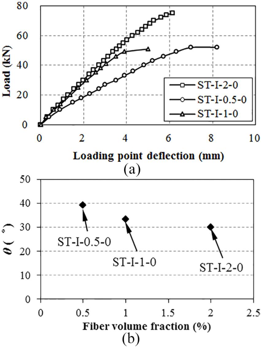
Effect of the fiber volume fraction on the shear behavior of UHPC beams. (a) load–deflection curves and (b) inclination of critical diagonal shear crack θ.
Effect of fiber type
The load–deflection curves of beams with different fiber types are compared in Figure 6(a). Before cracking, all beams exhibited similar load–deflection responses. However, the response of the beams demonstrated different shear behaviors for various fiber types, especially after shear cracking. As shown in Figure 6(a), the shear strength is not sensitive to the fiber type under the same fiber volume fraction. Figure 6(b) shows the fibers aspect ratio versus the angle of the critical diagonal crack. When the aspect ratio increased, the angle of the critical diagonal crack decreased.
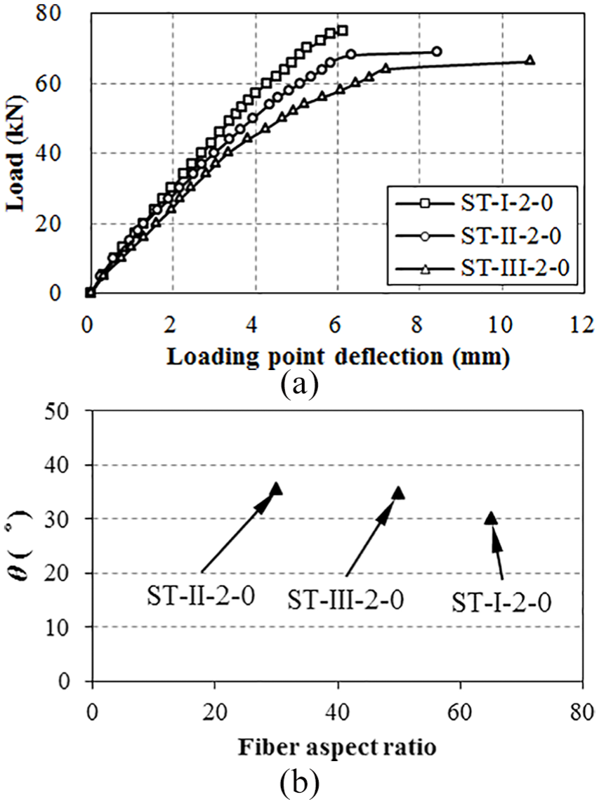
Effect of the fiber type on the shear behavior of UHPC beams. (a) load–deflection curves and (b) inclination of critical diagonal shear crack θ.
Effect of shear reinforcement
As shown in Figure 7(a), all beams exhibits similar load–deflection responses. However, the shear strength and ultimate deformation were definitely different due to the presence of the shear reinforcement. When the amount of shear reinforcement increased, the shear strength and ultimate deformation increased because the stirrups could directly sustain the increasing load and assist the redistribution of web concrete stress. Figure 7(b) illustrates that the shear reinforcement can restrain the propagation of diagonal cracks and increase the angle of the critical diagonal crack.
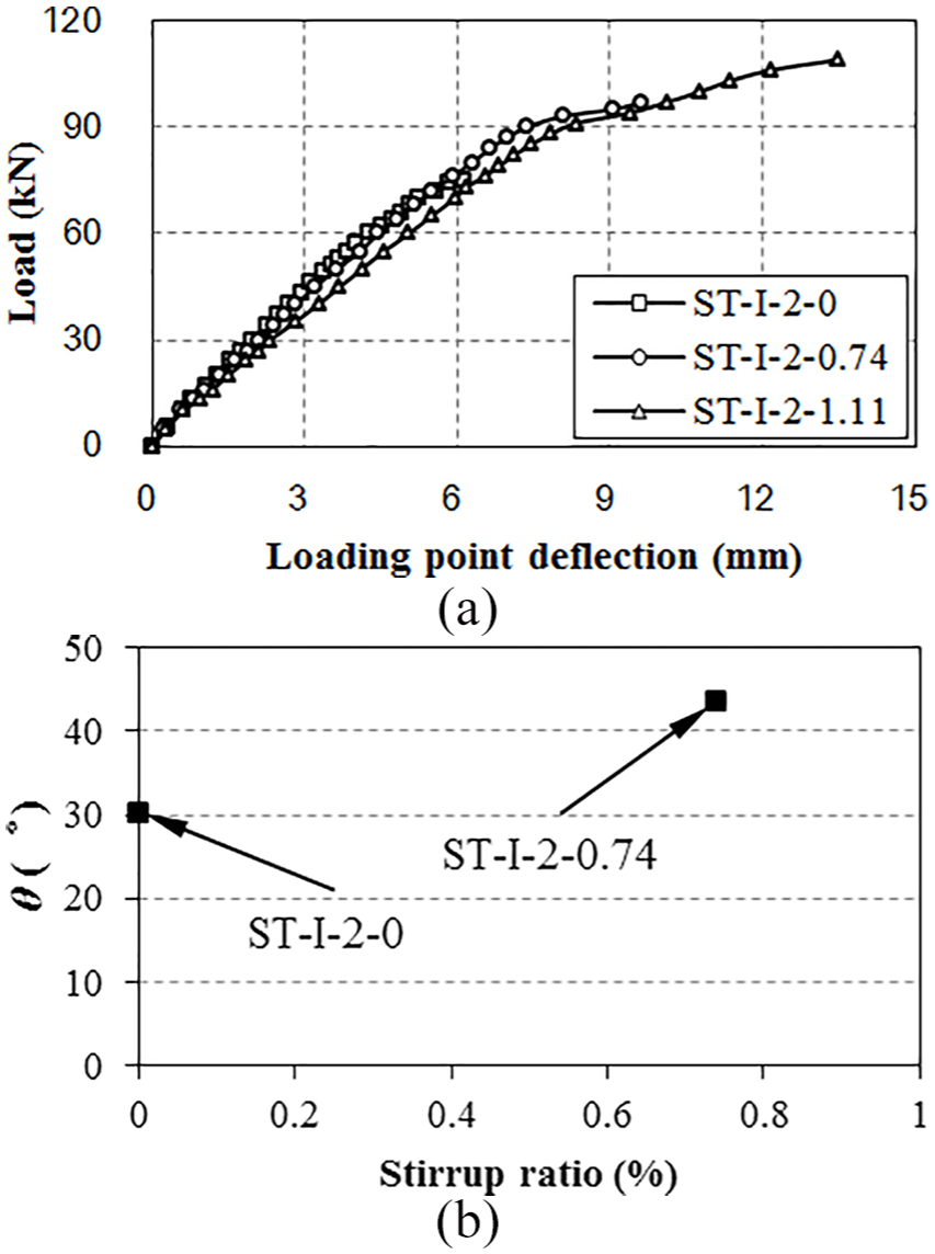
Effect of the shear reinforcement on the shear behavior of UHPC beams. (a) load–deflection curves and (b) inclination of critical diagonal shear crack θ.
Steel fibers as shear reinforcement
According to ACI 318-14 (ACI Committee 318, 2014), steel fibers can be used as the shear reinforcement for steel fiber–reinforced concrete (SFRC) beams when the normalized shear strength is greater than
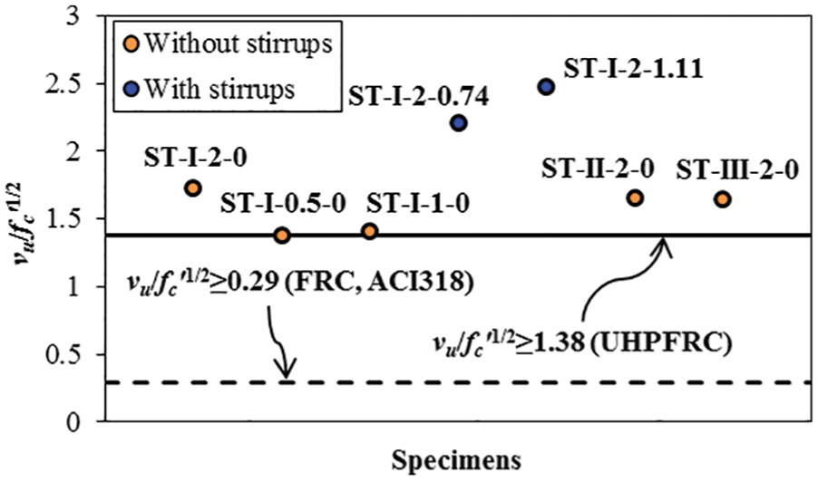
Lower bound of the normalized shear strength for the UHPC specimen.
Depth of compression zone considering the tension of UHPC
Basic assumption
The test results indicate that the compression zone concrete would not extensively crush due to the ultra-high compressive strength of UHPC. The linear strain distribution for the compression zone concrete can be assumed for simplicity. The residual tensile stress of UHPC remains relatively stable after the peak stress until the ultimate tensile strain due to strain hardening (Lee et al., 2017; Wille et al., 2014). In other words, one can use a constant residual tensile stress for cracked UHPC in the ultimate state for calculation simplicity. Therefore, as shown in Figure 9, in the derivation of the depth of the compression zone, the following assumptions are used: (a) the plane section remains planar and (b) the normal stress distribution of the compression zone satisfies a linear relationship, whereas the shear stress satisfies a parabolic relationship along the height of the compression zone.
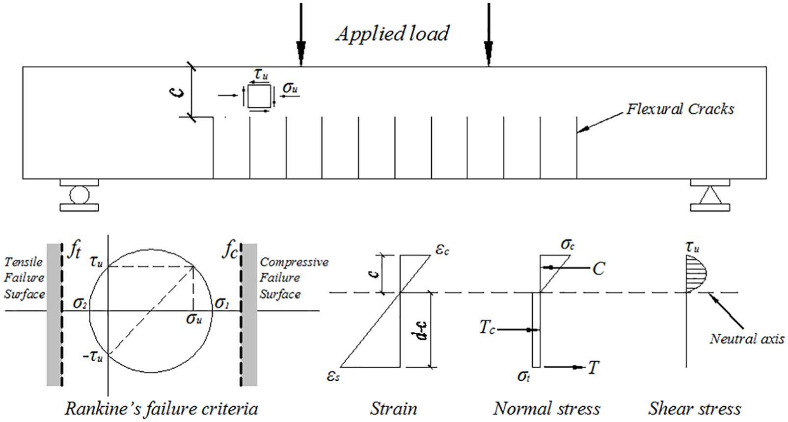
Failure criterion for concrete and stress and strain distribution.
Ultimate limit state
As shown in Figure 9, the compressive resultant force C and tensile resultant forces T and Tc at the cross-section can be expressed as


where σc is the compressive stress of concrete at the section edge, and the maximum value can be adopted as 0.85fcu when failure occurs; σs is the tensile stress in the longitudinal reinforcement; σt is the tensile stress of the cracked section, and the maximum value is the material tensile strength ft at the ultimate state; fcu is the compressive strength of UHPC; ρ is the longitudinal reinforcement ratio; b is the web width; d is the effective depth; and c is the compression zone depth.
Bernoulli’s compatibility equation is expressed as
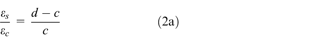
where εc and εs are the compressive strain of concrete at the section edge and tensile strain of main steel, respectively.
Equation (2) can be rewritten into the form of stress
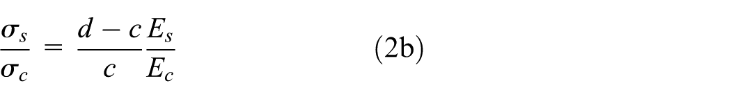
where Es and Ec are the elastic modulus of steel bars and concrete, respectively.
Using the equilibrium of forces (C = T + Tc) and replacing σs in equation (1b), the following equation can be obtained
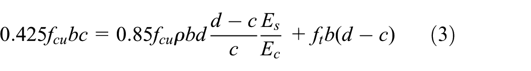
The tensile strength can be approximated as by 5% of the compressive strength according to the test result of Graybeal (2006)

Substituting equation (4) in equation (3) and using the definition of n = Es/Ec, c can be determined by the following equation

Serviceability limit state
Similarly, the derivation of the compression zone depth considers the compatibility of deformation and equilibrium condition of forces. However, the only difference is that the tensile strain in concrete at the tension side is equal to the tensile strain in the longitudinal reinforcement, and the tensile stress distribution of concrete satisfies a linear relationship, as expressed by

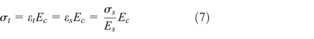
Thus, the force equilibrium equation is expressed as

Substituting equation (2b), equation (7), and n = Es/Ec, c can be determined as follows

Discussions and recommendations
According to the classical beam theory (He et al., 2012; Tureyen and Frosch, 2003), the depth of the compression zone can be determined by

The predictions of the depth of the compression zone using the proposed method and classical beam theory are compared based on benchmark beam ST-I-2-0, as shown in Figure 10.
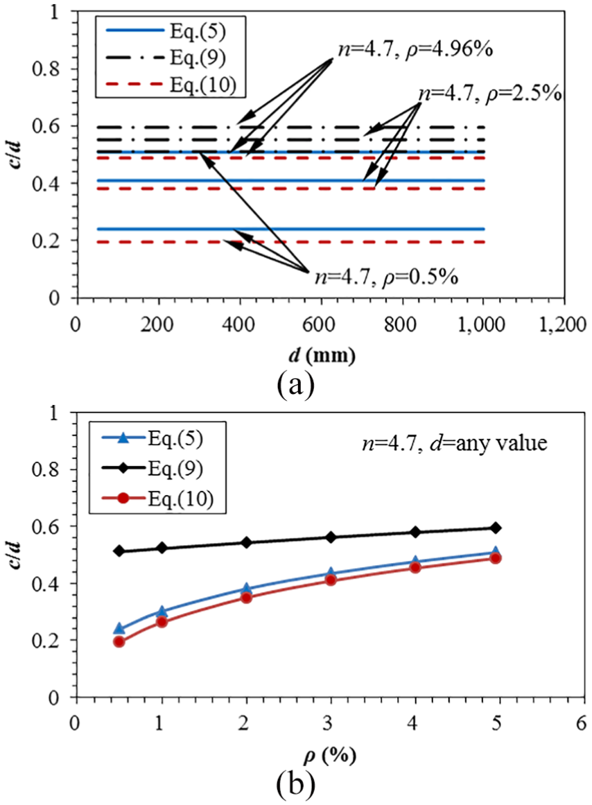
Comparison of the predictions of compression zone depth between the proposed method and the classical beam theory. (a) effective depth and (b) longitudinal reinforcement ratio.
Figure 10(a) indicates that for a given beam with a certain longitudinal reinforcement ratio, the ratio of the compression zone depth to the effective depth is constant. This ratio increases with the increase in longitudinal reinforcement ratio. The calculation result of the proposed method (equation (5)) is approximately equal to the prediction of the classical beam theory (equation (10)) for the ultimate state, whereas the prediction of the proposed method (equation (9)) is much larger than the prediction of the classical beam theory (equation (10)) for the serviceability limit state.
Figure 10(b) shows that the predictions of the proposed method and classical beam theory for the compression zone depth increase when the longitudinal reinforcement ratio increases. Similarly, the depth of the compression zone in the serviceability limit state is much larger than that in the ultimate limit state.
The predictions of the depth of the compression zone at different states of the proposed method and classical beam theory were compared based on the benchmark beam ST-I-2-0, as shown in Figure 11.
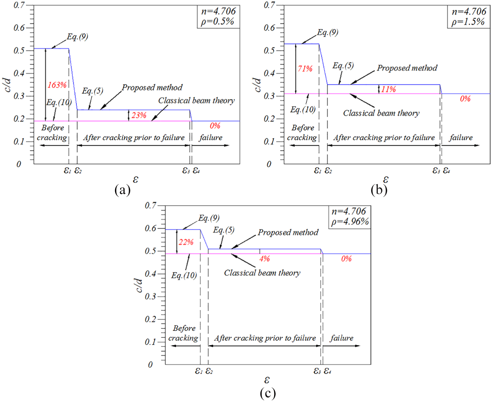
Comparison of the predictions of compression zone depth between the proposed method and the classical beam theory at different states. (a) ρ = 0.5%, (b) ρ = 1.5%, and (c) ρ = 4.96%.
The prediction of the classical beam theory is the lower bound of the actual compression zone depth. At the serviceability limit state before cracking, the compression zone depth with the consideration of concrete tension can be 22% larger than the value obtained without such consideration, although the beam is heavily reinforced with a longitudinal reinforcement ratio of 4.96%. Thus, the concrete tension should not be neglected in serviceability limit state analyses such as the cracking moment calculation. The situation varies for the state after cracking prior to failure. When the beam has a small amount of longitudinal reinforcement (ρ = 0.5%), the consideration of the concrete tension or lack thereof will cause a difference of 23% in the predicted compression zone depth; this difference is only 4% when the beam has a longitudinal reinforcement ratio of 4.96%. Consequently, for fiber-reinforced HSS–UHPC beams, the concrete tension can be neglected for simplicity when the beam is heavily reinforced and should be considered when the beam is lightly reinforced.
Shear strength model
Proposed formula
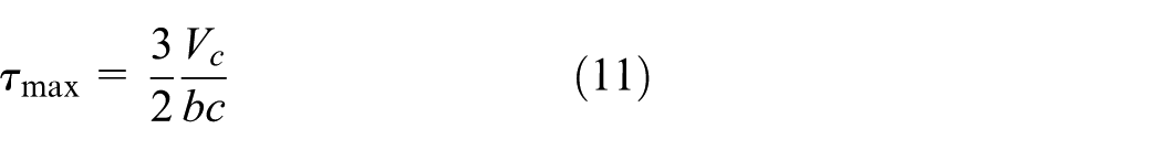
As shown in Figure 9, the maximum shear stress of the compression zone can be calculated by
According to the previous study (Qi et al., 2015; Wang and Qi, 2013), Rankine’s failure criteria can be used to define the failure mechanism of the compression zone subject to the combined bending stress and shear stress. In addition, the compressive stress did not reach the compressive strength according to the test observation due to the ultra-high compressive strength of UHPC. Thus, failure is assumed to occur when the principal tensile stress reaches the tensile strength of UHPC
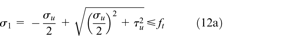
where σu is the normal stress in the ultimate state and τu is the shear stress in the ultimate state.
Equation (12a) can be rewritten as follows

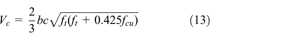
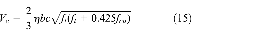
The normal stress is equal to σc/2 when the shear stress reaches the maximum value in Figure 8. Thus, by substituting equation (12b) in equation (11), the shear contribution of the compression zone concrete can be obtained
Tureyen et al. (2006) recommended the following coefficient η to consider the effect of the top flange on the shear contribution of the compression zone concrete of T-beams
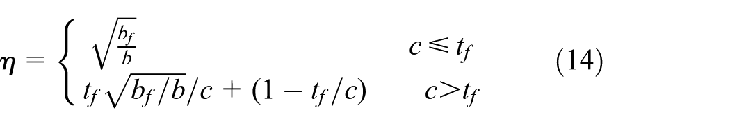
where tf and bf are the height and width of the top flange, respectively.
Therefore, the shear contribution of the compression zone concrete for T-beams can be expressed by
The truss model is used to estimate the shear contribution of the stirrups in this study

where ρv is the stirrup ratio, fv is the stress in the stirrup and can be taken as the yield strength, and α is the inclination of the compressive strut and assumed to be 45° for simplicity.
For the fiber shear contribution, Association Francaise de Génie Civil (AFGC-Sétra, 2013) provides a reasonable calculation method based on the tensile stress–crack width curves. The term for the participation of the fibers is
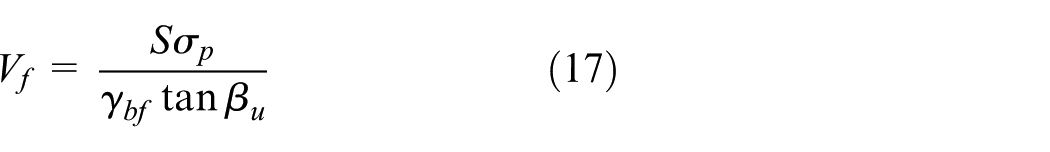
where S is the resistance area of fibers, estimated with 0.9b0d for rectangular or Tee sections; βu is the inclination of diagonal compression struts; γbf is the partial safety factor and equal to 1.3; and σp is the residual tensile strength and can be expressed as
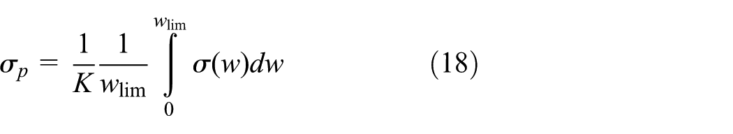
where K is the orientation coefficient, wlim is the maximum crack width and is recommended to be 0.3 mm in the French Code, and σ(w) is the stress at crack width w. In this study, the stress versus crack width relation is assumed to be linear, and the residual tensile strength σp can be approximately estimated as the average stress level that corresponds to zero crack width and a crack width limit of 0.3 mm.
Experimental verification
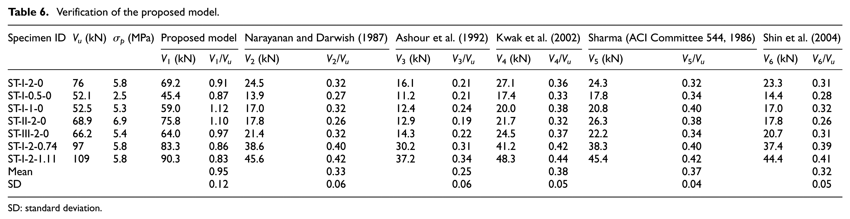
Since there is lack of shear strength model for UHPC beams, shear strength equations for SFRC beams in the literature were collected to predict the shear strength of test beams and compared with the proposed model (ACI Committee 544, 2009; Ashour et al., 1992; Kwak et al., 2002; Narayanan and Darwish, 1987; Shin et al., 1994). Table 6 shows the calculation results. The average fiber matrix interface bond stress was taken as 10 MPa for smooth fibers and the UHPC matrix, as recommended by Wille and Naaman (2012). The mean ratio of the proposed model to the experimental results is 0.95 with a standard deviation of 12%. The mean ratios of the shear strength equations established by Narayanan and Darwish (1987), Ashour et al. (1992), Kwak et al. (2002), Sharma (ACI Committee 544, 1986) and Shin et al. (1994) to the experimental results are 0.33, 0.25, 0.38, 0.37, and 0.32 with standard deviations of 6%, 6%, 5%, 4%, and 5%, respectively. The proposed model reached a good agreement with the test results, while all equations in the literature over underestimated the shear strength of the test beams.
Verification of the proposed model.
SD: standard deviation.
Conclusion
An experimental and theoretical study was performed on the effect of the fiber volume fraction, fiber type, and stirrups ratio on the shear behavior of a new type HSS–UHPC beam. Based on the test results and theoretical analysis, the following conclusions can be drawn:
The shear failure in HSS–UHPC beams is not brittle and catastrophic but displays ductility characteristics. Shear reinforcement need not be provided for HSS–UHPC beams with a fiber volume fraction of 0.5%, which requires further verification by more test data.
Unlike conventional reinforced concrete beams, many short fine diagonal shear cracks appeared and propagated around the existing crack with small spacings, which significantly improves the shear behavior of the test beams. Although fibers can be considered dispersed tiny reinforcement in a beam, a moderate quantity of stirrups should be contained in a UHPC beam to attain a superior structural behavior.
Instead of neglecting the concrete tension in conventional concrete beams, the depth of HSS–UHPC beams considering the concrete tension was determined from the deformation compatibility condition and force equilibrium equation in different states, including the serviceability limit state and ultimate limit state.
For fiber-reinforced HSS–UHPC beams, the concrete tension should be considered in serviceability limit state analyses such as the cracking moment calculation. After cracking, the concrete tension can be neglected for simplicity when the beam is heavily reinforced but cannot be neglected when the beam is lightly reinforced.
A shear strength model based on Rankine’s failure criteria, the truss model, and AFGC-Sétra was proposed and verified by the test results. The mean value of the ratio of the proposed model to the experimental results was 0.95 with a standard deviation of 12%.
Footnotes
Declaration of Conflicting Interests
The author(s) declared no potential conflicts of interest with respect to the research, authorship, and/or publication of this article.
Funding
The author(s) disclosed receipt of the following financial support for the research, authorship, and/or publication of this article: This study was supported by the National Natural Science Foundation of China (Grant No. 51438003), which was gratefully appreciated.