
Abstract
A built-up I-section with web stiffeners and complex edge stiffeners is expected to have better performance to resist against local and distortional buckling compared to conventional built-up I-section. In order to study the influence of perforations on compression behavior of above section forms, a series of pin-ended compression tests and numerical analysis on perforated double-limb cold-formed steel built-up I-section columns with complex edge stiffeners and web stiffeners were conducted. The test specimens contained 12 concentrically loaded specimens and 8 eccentrically loaded specimens with two cross-section shapes, respectively. The test results were found that the web stiffeners could obviously increase the ultimate bearing capacity of the built-up members, especially for stub and medium-long columns. The ultimate bearing capacity of two cross-section shaped medium-long columns decreased gradually with the increase of eccentricity. Two adjacent single-limb webs of conventional built-up I-section could provide support to each other. The web stiffeners restricted the deformation of the plate around the holes effectively, but it also weakened the composite action between the single-limb webs. A finite element model was developed and verified against experiments of perforated built-up columns. Furthermore, a total of 96 parametric analyses were completed to investigate the optimal ratio of the hole depth to web sub-element in the Σ-shaped built-up I-section perforated columns. Finally, two types of direct strength method formulas were used to calculate the ultimate bearing capacity of perforated built-up specimens. The appropriateness of those direct strength method was compared. It was shown that the existing direct strength method formulas were both valid for perforated built-up I-section columns with complex edge stiffeners.
Keywords
Introduction
Cold-formed thin-walled steel member is fabricated by cold rolling or press braking the thin steel sheet or strip sheet. It is widely used in the residential construction field due to its significant advantages such as being light-weight, cost-effective, short construction period, and recyclable. In light-weight steel joist system of low or multi-rise residential housing, when higher local rigidity or greater loading are required, built-up section columns are often specified. They are often used as chord studs of the wall steel skeleton. In thin-walled members, small details in the cross-section are critical, particularly when they serve to retard buckle and cross-section instability (Schafer et al., 2006). For example, a built-up I-section with web stiffeners and complex edge stiffeners is expected to have better performance to resist against local and distortional buckling compared to built-up I-section without these. Certain quantities of web holes on columns are usually needed for laying the pipes, increasing the structural regularity and reducing the weight. However, perforations cause the reduction of structural stiffness and bearing capacity, which also make the stress distribution more complicated. Therefore, the focus of this study is to investigate about the loading behaviors of perforated built-up specimens with longitudinal web stiffeners and complex edge stiffeners.
At present, the load-carrying capacity of conventional individual channel members with web holes was studied more with experiments and theoretical analysis (Kulatunga et al., 2014; Moen and Schafer, 2008, 2009, 2011; Yao and Rasmussen, 2017b; Yao et al., 2011). However, the study on the stability of individual Σ-shaped members with web holes and complex edge stiffeners was relatively rare. The experimental and numerical results of Wang et al. (2015) indicated that the loading efficiency of this section type of specimens was increased about 30%–50% relative to that of webs without stiffeners under compression. The bearing capacity of the member could be significantly increased by longitudinal web stiffeners. This result provided basic reference on bearing capacity study of the Σ-section built-up members with web holes under compression.
Within the past decade, research on built-up cold-formed steel columns had increased, which mainly includes box closed built-up section and double-limb or multi-limb built-up section. But most of them were concentrated on the condition that conventional lipped channels were used as single-limb of the built-up member, which did not include complex edge stiffeners, web stiffeners, and holes (Becque and Rasmussen, 2009a, 2009b; Craveiro et al., 2016; Fratamicoa et al., 2018; Li et al., 2014; Liao et al., 2017; Liu and Zhou, 2017; Reyes and Guzmán, 2011; Tina et al., 2017; Whittle and Ramseyer, 2009). Limited literature has reported the effect of web stiffeners on built-up columns; Young and Chen (2008) and Zhang and Young (2018) presented experimental investigations about built-up closed sections with longitudinal web stiffeners between fixed-ends. The load-carrying capacity of that section at various lengths and the effect of composite action were observed in these experiments. Zhang and Young (2012, 2015) performed a series of full-scale tests, numerical analysis and design investigation on double-limb Σ-section built-up I-section columns with simple edge stiffeners between fixed-ends. The results indicated that the load-carrying capacity predicted by AISI S136-2016 (2016) and AS/NZS 4600 (2005) standard was conservative. Furthermore, an equivalent method for calculating the critical buckling stress of such built-up members was presented, which could be used conveniently to design the bearing capacity of the members by direct strength method (DSM). Georgieva et al. (2012) performed a series of experiments on the behavior of built-up columns using combination of three or four Z-sections, Σ-sections, and lipped channels. By changing the various built-up section types, the columns with the relative maximum bearing capacity were found.
In domestic and foreign research, there is relatively less study about built-up columns with web hole till now. An experimental investigation on perforated double-limb built-up I-sections under axial compression was completed by Stone and LaBoube (2005). The channel section with simple edge stiffeners was used as single-limb of the built-up member. In this study, the load-carrying capacity of the members was calculated by comparing the AISI with the modified slenderness ratio method. However, the influence of holes on the stability behavior of the built-up members was not analyzed thoroughly.
In summary, the research on the stability of perforated double-limb channel built-up columns with complex edge stiffeners and longitudinal web stiffeners is still rare. So a series of pin-ended specimens mentioned above were tested in compression, analyzed by parametric study, and calculated by DSM of perforation in this article. This investigation could promote the engineering application of the complex and high-efficiency cold-formed thin-walled steel built-up section members.
Experimental investigation
A total of 20 built-up I-section members were tested between pinned-ends subject to compression. It contained two kinds of single-limb section shapes (see Figure 1(a)): lipped channels with web holes and additional return lips (named DC1 section), and Σ-shaped section with web holes and complex edge stiffeners (named DC2 section). Twelve specimens were tested under concentric loading with the other specimens under eccentric loading.
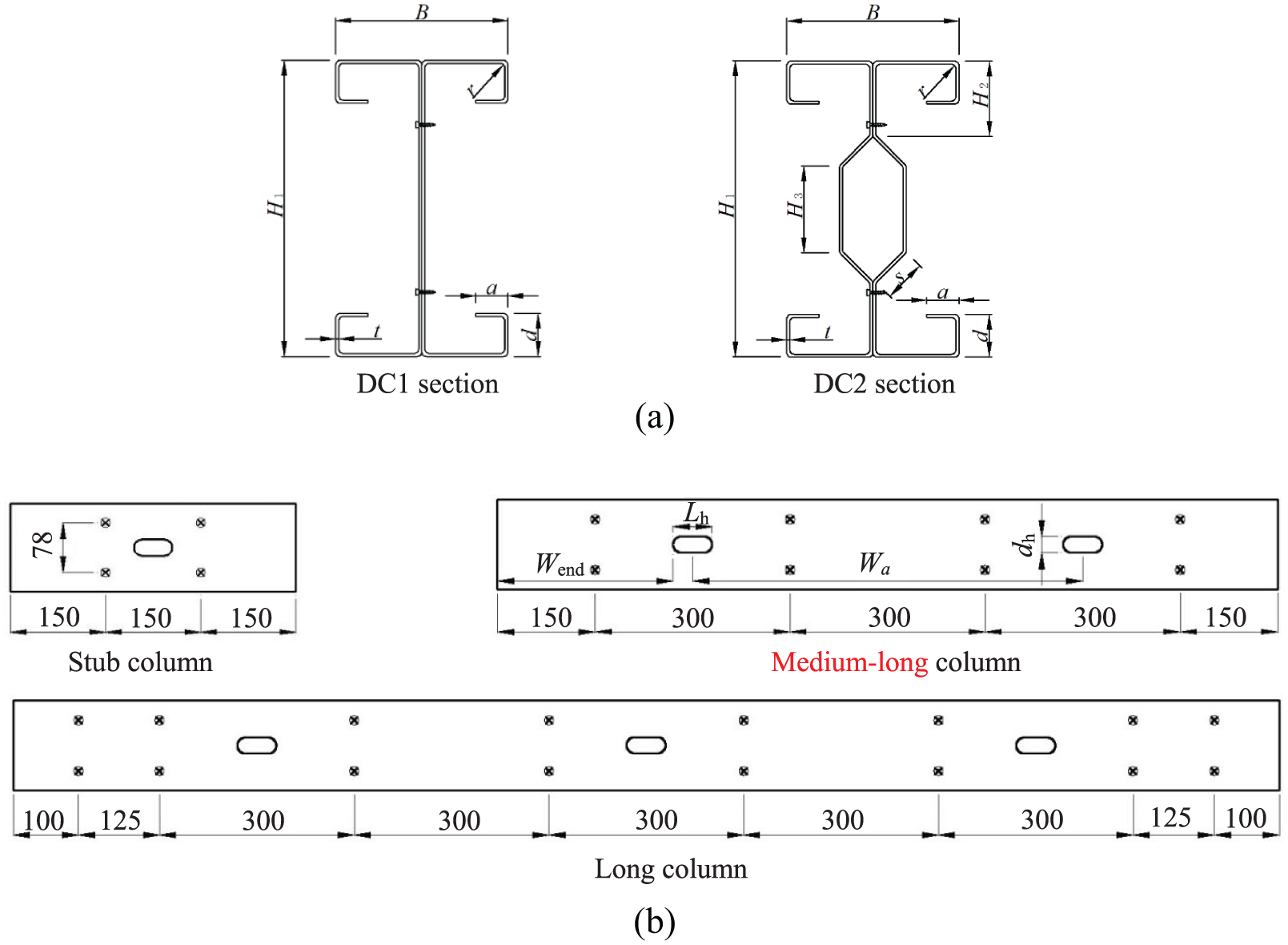
Definition of geometric parameters and screw arrangement of specimens: (a) transverse direction and (b) longitudinal direction.
Test specimens
Three lengths of column (L) were selected for the two section form members in tests. The effect of holes on the ultimate bearing capacity, the bucking modes, and the interaction between limbs were studied under different slenderness ratios. It included 4 stub columns, 12 medium-long columns, and 4 long columns, respectively.
The webs of the members were perforated with oval holes. One opening was arranged at mid-length of short columns. As the length increases, the number of holes also increased. The definition of symbols for the hole was shown in Figure 1(b). The dimension of the hole was determined according to Chinese technical specification of cold-formed steel structure (JGJ227-2011, 2011). Self-tapping screws were used to connect two single limbs together. Its arrangements were based on the observation of the actual situation in cold-formed steel structures design. The transverse spacing of all screws was set at 78 mm. The longitudinal spacing of the screws was set at 150, 300 and 300 mm for short columns, middle-long, and long columns, respectively. The screws near two ends of the long column were arranged closer (Figure 1(b)). The nominal sizes of the members, which is defined by surface outline, were shown in Table 1. The rounded inside corner radius (r) is 1.4 mm, and the bending angle of the DC2 section web-stiffener is 45°. In this article, slenderness ratio (λ) was determined according to the overall section features of the built-up column specimens; after calculation, λ around weak axial was largest and used for column specimens with section DC1 and DC2. The actual sizes of specimens were measured before tests and the results were listed in Table 2. As shown in Table 2, the label of the specimens was listed in the first column and the detailed meaning of letters was illustrated as follows. DC1 or DC2 indicated the two types of built-up sections, respectively; the letter L and the digits followed by meant the length of the specimen; the letter E and the digits followed by represented the nominal eccentricity, while the axial compression members did not have this item; the letter H indicated specimens with web holes; the letter a and b at the end meant the two built-up column specimens with the same design parameters, respectively.
Design dimensions of specimens.

Actual dimensions of specimens.
The tracks were installed on both ends of the specimens by the self-tapping screws in order to reflect the actual boundary conditions of wall studs. Furthermore, each track was connected to a 10 mm thick end plate (300 × 300 mm) by eight bolts for avoiding the influence of welding and the ease in loading. The tenon was then welded on the center of end plate for connecting with the knife hinge conveniently.
Material properties
The material properties of the built-up column specimens were obtained through the test results of tensile coupons. It was according to the Chinese Standard (GB/T 228.1-2010, 2010). A total of eight longitudinal coupons were cut from the same batch of the column specimens to measure the metal properties. The average values of coupon tests were as follows. The measured yield stress (fy), the tensile strength (fu), the elasticity modulus (E), and the Poisson’s Ratio (υ) of the specimens were equal to 381.64 MPa, 611.53 MPa, 202.915 MPa, and 0.29, respectively. The elongation (δ) after fracture based on the gauge length was 23.84%. They were used as the material properties of the specimens.
Geometric imperfections
The ultimate bearing capacity and deformation behavior of thin-walled steel are affected by geometric imperfections obviously. Thus, the initial imperfections of each specimen must be systematically measured before the test. In order to gauge the local and distortional imperfections for built-up section specimens, the single-limb members were meshed into 50 × 50 mm parts and marked along the width and the length before measuring. After that, the imperfections were measured at the intersection of the grid lines by dial gauges. The minor axis overall imperfections were measured only for medium and long column specimens, since it has little influence on stub column specimens.
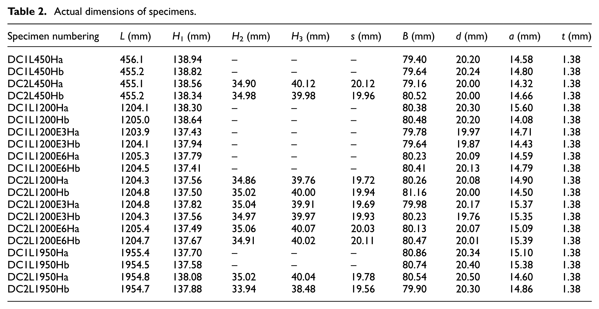
The imperfection symbols and the measuring point were shown in Figure 2. The local imperfections of the web were defined as Δ w ; Δ rf and Δ lf referred to left and right flange imperfections, respectively. The distortional imperfections at the junction of lip and flange were Δ rd for the right side and Δ ld for the left side. The minor axis overall imperfections (Δ L ) was defined as the average of Δ1, Δ2, Δ3, and Δ4 to eliminate the influence of section torsion and reduce the measuring errors. The detailed measurement method and device were shown in reference (Wang et al., 2016; Zhang et al., 2007).
Measurement positions of initial geometric imperfections: (a) local and distortional imperfections and (b) overall imperfections.
The measured maximum absolute value of imperfections was given in Table 3 for each specimen.
Initial imperfection of test specimens.

Test rig and gauge arrangement
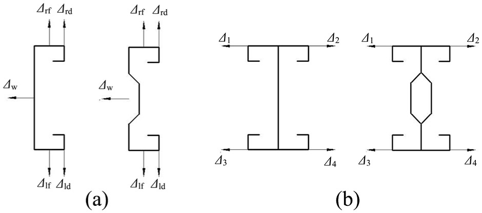
The built-up columns were loaded to apply compressive load by 600 kN capacity hydraulic testing machine. As was shown in Figure 3(a), both ends of specimens were provided the simply supported boundary condition by knife-edge hinges with one direction (see Figure 3(b)). It was allowed to rotate about the minor axis, while torsion and warping about the vertical axis, rotation about the major axis were restricted. Moreover, a pressure sensor was set in the prepared hexagonal groove to connect knife edge on the top and a fixture was applied to fix the knife-edge at the bottom of the specimen on the ground.
Test setup and single direction knife-edge hinges: (a) test setup and (b) the device of single direction knife-edge hinges.
Lateral displacement transducers and strain gauges were generally arranged near the mid-height of the built-up columns. The axial displacement transducers (1 and 2 displacement transducers) were applied at the loading line inside the end plate on both sides of the member. Their average results were determined as the built-up column axial shortening. The strain gauges of the medium-long columns were arranged on both sides of the two holes. It was named as 5–8 and 9–12, respectively, while the strain gauges of the stub and long columns were only arranged on both sides of the central hole. Detailed layout was shown in Figure 4.

Strain gauges and displacement transducers arrangement: (a) stub columns and long columns and (b) medium-long columns.
Testing loading eccentricity determination
The stability behavior and strength of cold-formed thin-walled members can be easily influenced by the position of loading; there is difference between the real eccentricity determined by tests and the nominal eccentricity defined before experiments. It is influenced by a series of factors such as the error of track installation, systematic error of testing equipment, and initial geometric imperfections. In this article, the nominal stress gradient coefficient was calculated according to the measured strain results in the initial elastic loading phase; the testing actual loading eccentricity (e) was inversely calculated using the method presented in reference Zhang et al. (2007).
Test results and analysis
Stub column
Typical failure modes of stub columns were shown in Figure 5. The failure mode of DC1 specimens involved local and distortional buckling as well as the interaction of these buckling modes. Distortional buckling was observed for specimens with the other shapes of section. Three local buckling half waves appeared along the longitudinal direction of DC1 stub columns. The half wavelength around the hole was larger than that of close to the ends. One individual member appeared outward distortional buckling, and at the summit value point of distortional buckling, the maximum local buckling deformation can be observed. Meanwhile, the other single-limb members presented inward distortional buckling. The web deformation between the two individual members was consistent. For DC2 short columns, only one distortional buckling half wave appeared along the length of the columns. It was also observed that one single-limb member emerged inward deformation and the other occurred outward deformation. Because the web stiffener reduced the width-to-thickness ratio of the plate, and enhanced the critical local buckling stress effectively, the distortional buckling became the governing failure mode of DC2 stub columns. It was also found that the local buckling occurrence of DC1 stub columns was prior to that of distortional buckling. Then with the load increasing, bucking deformation around the hole increased gradually. However, for DC2 stub columns, there was an obvious difference between the deformation around the hole on the web of two individual members. The deformation around the hole of one limb with inward distortional buckling was significant, but it was not obvious on the other limb with outward distortional buckling. The screw was no sheared break or pull out during the tests, and the deformation coordination between the two single-limb members was well under this screw spacing. It was shown that the screw spacing is applicable to above two sections.
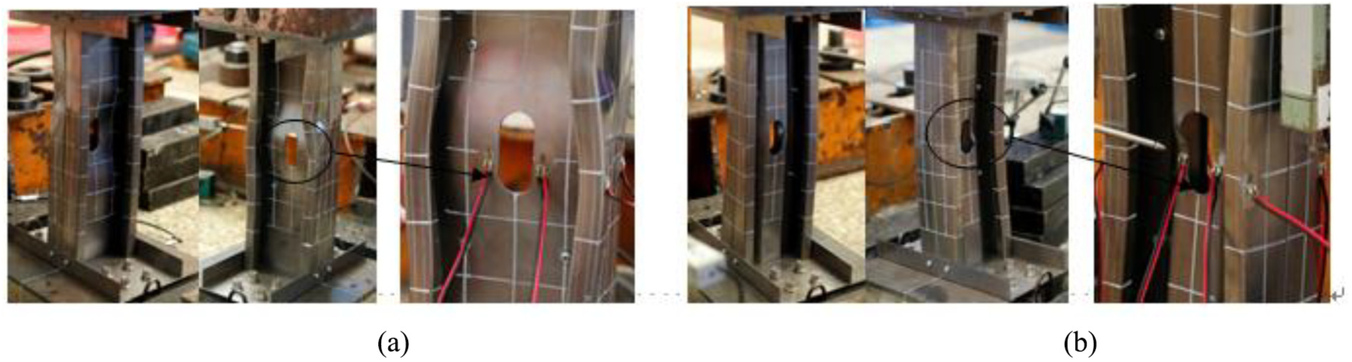
Failure modes of stub columns: (a) DC1L450Ha and (b) DC2L450Ha.
Figure 6 showed the typical load versus strain curves near the hole of stub columns. It could be seen that strain reversal phenomenon (Mulligan, 1983) happened at the measuring point when the specimens were loaded to about 75 and 250 kN for DC1L450Ha and DC2L450Hb, respectively. It demonstrated that loading coordination effect was well between the single-limb members. Meanwhile, the plate critical local buckling load was effectively enhanced by web stiffeners.
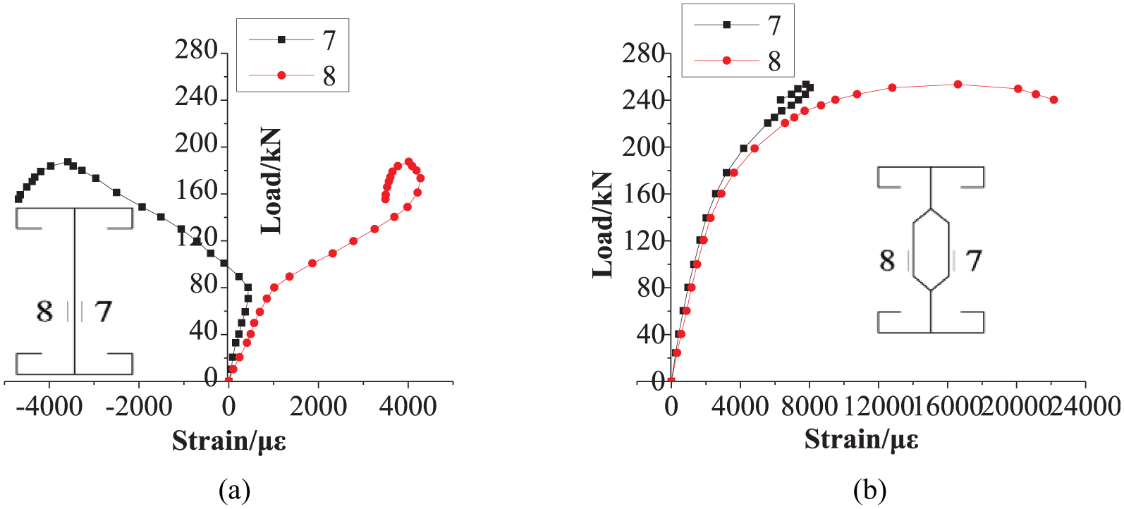
Load versus strain curves: (a) specimen of DC1L450Ha and (b) specimen of DC2L450Hb.
Experimental results of stub columns were listed in Table 4. It indicated that the ultimate bearing capacities of DC2 built-up section were much higher than that of DC1 built-up section, which showed that the load-carrying capacity of built-up section stub columns could be enhanced by longitudinal web stiffeners significantly.
Tests and numerical analysis results of specimens.

L, D, and F represented local buckling, distortional buckling, and overall flexural buckling, respectively.
Load versus axial displacement curves of stub column specimens were drawn in Figure 7. It illustrated that the curve of DC2 dropped suddenly in its post-ultimate state, but it dropped relatively gradually for DC1 specimens. This was mainly influenced by buckling modes. The deformation of post-distortional buckling developed suddenly and that of post-local buckling developed relatively gently.
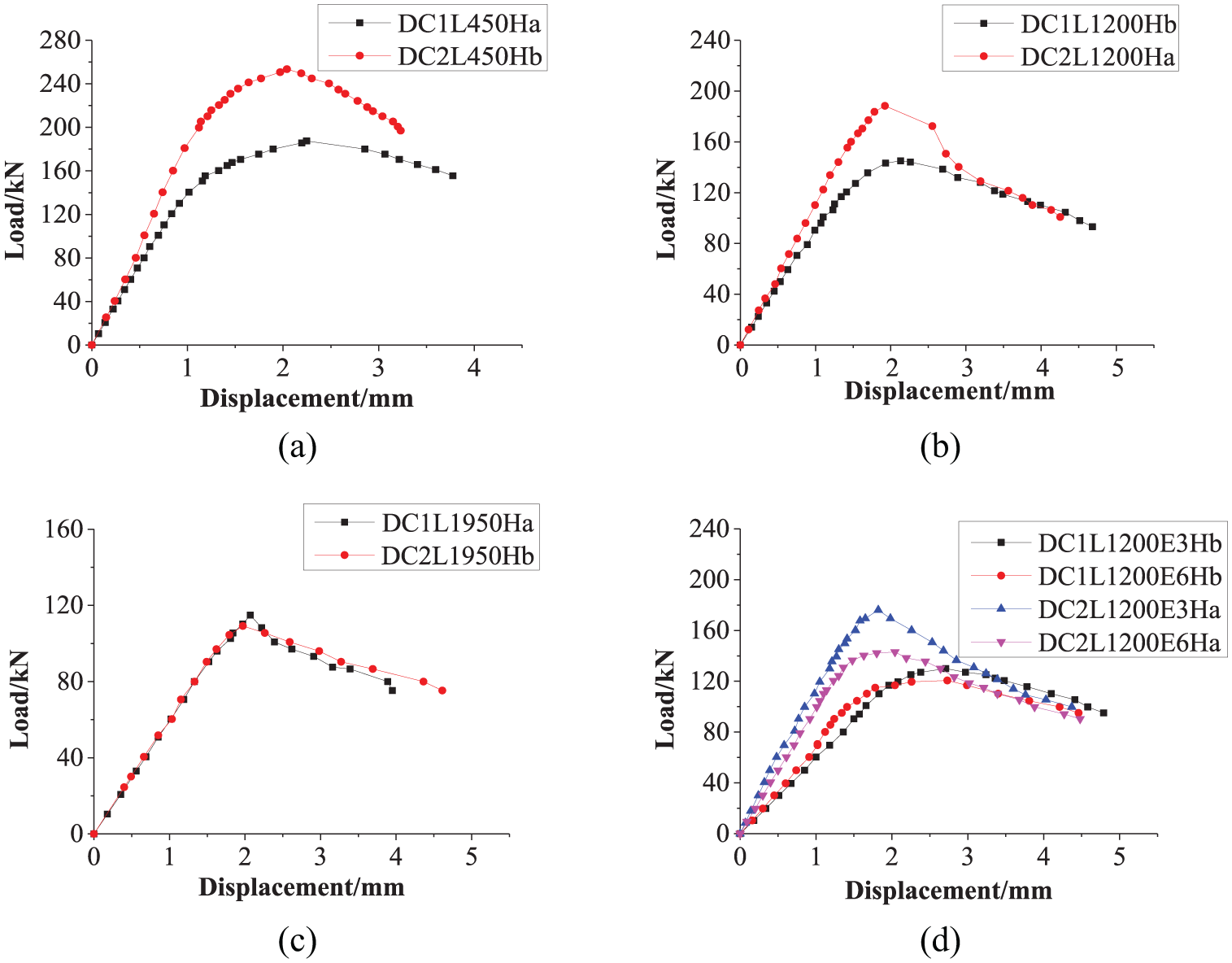
Load versus axial displacement curves of specimens: (a) axially loaded stub column, (b) axially loaded medium-long column, (c) axially loaded long column, and (d) eccentric compression medium-long column.
Medium and long column
Two types of failure modes were observed in medium and long columns. The DC1 specimens failed in local, distortional, and overall buckling as well as the interaction of these buckling modes, while failure modes of specimens with the other section shape involved distortional and global flexural buckling as well as their interactive buckling. Typical failure modes of built-up medium and long column were shown in Figure 8 for specimens subjected to concentric loading and eccentric loading, respectively. It could be seen that the maximum deformation basically occurred at or near the mid-height of columns. For medium and long column specimens of DC1 section, web occurred in multi-half-waves local buckling along the length of the specimens (see Figure 8(a), (c), and (e)). The half-wave length of the outward convex local buckling (along the flexure direction of the specimen) was larger than that of inward concave local buckling. It indicated that two adjacent single-limb webs of built-up I-section could provide some certain support to each other, so as to partially restrain the inward concave local buckling deformation. Only one distortional buckling half wave occurred along the longitudinal direction of specimens, which showed that the flanges of one limb were concave on both sides and the other limb flanges were convex on both sides. The local buckling at the web hole position made the web around the hole separate from each other.

Typical failure mode pictures of medium and long columns: (a) DC1L1200Ha, (b) DC2L1200Hb, (c) DC1L1200E6Ha, (d) DC2L1200E3Ha, and (e) DC1L1950Ha.
Affected by the longitudinal web stiffeners, the contact area of the adjacent single-limb webs was limited for DC2 specimens. So its composite action between the two webs was lower than that of DC1 specimens. Compared with DC1 long columns, it was found that the buckling deformation around the hole of DC2 specimens was relatively small. This indicated that web stiffener could restrict the deformation of plate around the hole. The local buckling of the web was controlled effectively. The overall flexural buckling mode of the long columns was more significant for the buckling control, but the distortional buckling was not obvious compared with medium-long columns.
Test results of medium and long column specimens were listed in Table 4. It indicated that the ultimate bearing capacity of DC2 section long columns was slightly lower than that of DC1 section influenced by initial eccentricity. The ultimate bearing capacity of two types of section shaped by medium-long columns decreased gradually with the increase of eccentricity. With the increase of length, the difference of the ultimate bearing capacity between these two section shapes decreased gradually. This is because when slenderness of column increased, the overall flexural buckling modes probably occurred at weaker axis for both DC1 and DC2. The web stiffener was located near the section neutral axis, which has little effect on the moment of inertia about the minor axis.
Typical load versus axial displacement curves of medium and long column specimens were drawn in Figure 7. It was observed that the compressive loads of DC2L1200Ha and DC1L1950Ha dropped rapidly after the ultimate state due to the overall buckling of axial compression members. But the curves of DC1L1200Hb and DC2L1950Hb dropped relatively gently in its post-ultimate state influenced by initial eccentricity. The same change regulations of curves were also illustrated in eccentrically loaded specimens.
Comparison of numerical analysis and test results
Finite element model (FEM)
ANSYS16.0 was applied to simulate the compressive behavior of the two kinds of section columns. The element SHELL181 was selected for the finite element analysis (FEA). The material behavior was taken from the tensile coupon test. The isotropic hardening rule and the Von Mises yield criterion were used for the investigated steel. The initial loading eccentricities and actual dimensions determined by experiments were adopted in FEA. The appropriate element size was determined by repeated trial calculations and adjusting sizes of the elements, which was shown that the numerical results were more accurate when the element size away from the holes was about 10 × 10 mm. Considering the effect of the complexity of stress distribution and stress concentration phenomenon, element refinement processing was performed around the web holes.
In the FEM, a flexible contact type was selected and a surface to surface contact method was built between each limb of the column. TARGET170, CONTA174, and 0.3 were used as the target unit, the contact unit, and the friction coefficient, respectively. Three translational degrees of freedom, UX, UY, UZ, of the screws were coupled at the node of the screw connection position. Detailed simulation method about the experiment simply supported boundary condition that was shown in reference Wang et al. (2015, 2016). The distance between the both knife edges at two ends represents specimen’s effective length.
The eigenmodes of the built-up specimens performed to be established by the eigenvalue elastic buckling analysis. Then, in the process of nonlinearity buckling analysis, the maximum amplitude of the geometric imperfections about local, distortional, or global flexural which measured for each column before experiments was considered, and the arc-length method was applied.
Analysis of the results
According to the research of reference (Young and Rasmussen, 1998), it was found that the residual stress at the corner regions is less than 7% of the steel yield strength. Meanwhile, the increase of yield strength due to cold-forming exists primarily in corner regions also. They have the opposite effect and could be approximately neutralized by each other (Schafer and Peköz, 1998). So the enhancement of yield strength and the residual stress by cold-forming process were not modeled in this study. Analysis results were listed in Table 4. The comparison of failure modes and load versus axial displacement curves between experiments and FEA of certain built-up columns were drawn in Figure 9. It was shown that the difference of ultimate bearing capacity between results in experiment and FEA was less than 5%. Meanwhile, the failure modes of them agreed well with each other. Therefore, the validity of the FEM developed in this article had been verified. After that, further parametric investigation can be proceeded to study the buckling behavior of the members above.

Comparison of tests and FEA: (a) comparison about failure mode of DC1L1950Ha, (b) comparison about failure mode of DC2L450Ha, (c) comparison about failure mode of DC2L1200E6Hb, (d) comparison about load versus end shortening curves of DC1L1950Hb, and (e) comparison about load versus end shortening curves of DC2L1200E6Ha.
Due to the error factors mentioned above, the quantitative comparison of the bearing capacity between specimens with different sections was not accurate. Therefore, the uniform initial imperfections and the design nominal size were adopted in FEA once again to compare the load-carrying capacity of perforated built-up column specimens with different sections exactly. The analysis results of all specimens with design nominal size were listed in Table 5. In this article, the ultimate bearing capacity (Puf) to the yield load of the net section (Pynet, Pynet = fy × An, where An is the net section area) ratio was defined as loading efficiency (η). It was used to compare the bearing capacity between the two different section shapes under the same condition. The results indicate that compared with DC1 section, the loading efficiency of DC2 section increased about 32%, 11%, 11%, 13%, and 2% for stub columns, axially loaded medium-long columns, eccentrically loaded medium-long columns (with 3 or 6 mm eccentricity), and long columns in axial compression, respectively. Compared with DC1 medium-long columns subjected to axial compression, η of DC1 medium-long columns with 3 or 6 mm eccentricity was decreased about 15% and 30%, respectively. And for DC2 members under the same condition, the numerical value became 15% and 28%, respectively. It shows that the steel utilization ratio and the bearing capacity could be increased effectively by longitudinally stiffened web of double-limb built-up section, especially for stub and medium-long columns.
Numerical analysis results of design size.
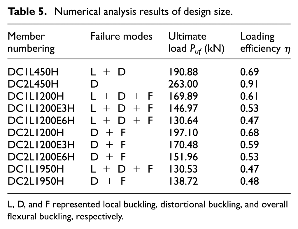
L, D, and F represented local buckling, distortional buckling, and overall flexural buckling, respectively.
Parametric analysis of Σ-shaped built-up section column with web holes
According to the results of experiments and analysis above, it is observed that the influence of holes on the stability behavior and strength of Σ-shaped section members is different from that of the other sections. However, how to choose the proportion of web hole and web sub-element in order to optimize the perforated Σ-shaped section still needs further investigation.
Variable selection and analysis results
For parametric analysis, one type of web height (H1 = 140 mm), three types of specimen length (L = 600 mm, L = 1200 mm, and L = 1800 mm), two types of metal thickness (t = 1 mm and t = 2 mm), two types of web sub-element height (H2 = 36 mm, H3 = 40 mm, and H2 = 26 mm, H3 = 60 mm), and seven types of web hole to web sub-element ratio (dh/H3 = 0.3, 0.5, 0.6, 0.7, 0.8, 0.9, and 1) were defined as variables. The width of hole (Lh) was unified as 80 mm. Other section sizes were the same as those of the members in experiments. The yield stress, the Poisson’s ratio, and the Young’s modulus in parametric analysis were defined as 345 MPa, 0.3, and 2.06 × 10⁵ MPa, respectively. Meanwhile, the transverse and longitudinal screw spacing of the FEA specimens was 100 and 300 mm, respectively. The stability behaviors of totally 96 pin-ended concentrically loaded samples were studied by FEA. The detailed meaning of specimen label was as follows. DC2N (H2 = 36 mm, H3 = 40 mm) and DC2W (H2 = 26 mm, H3 = 60 mm) indicated two types of Σ-shaped built-up section with different web sub-element width, respectively. Letter T and the digits followed by represented metal thickness. Letter L and the digits followed by meant the length of specimen. The last letter H and the digits followed by indicated the ratio of hole depth to web sub-element (dh/H3), while member without hole did not have this item.
The influence of dh/H3 on bearing capacity and failure mode analysis
According to the results of FEA, ultimate bearing capacities of members with dh/H3 = 1 were descended 10%–24% and 9–20% compared with no perforated members under t = 1 mm and t = 2 mm thickness, respectively. Meanwhile, the decrease rate of stub columns is larger than that of medium and long columns. In order to observe the variation trend more intuitively, the relationship between loading efficiency and dh/H3 of DC2 series columns were plotted in Figure 10. In which, dh/H3 = 0 means no perforated DC2 section. It could be seen that loading efficiency increased gradually with the change of dh/H3 from 0 to 0.7, and it kept about the same value during dh/H3 equals to 0.7 and 0.8. But when dh/H3 was larger than 0.8, the loading efficiency of t = 1 mm started reducing, and it approximately remained unchanged for t = 2 mm. Therefore, for the case of dh/H3 = 0.7–0.8, the loading efficiency is relatively high and stable for all series Σ-shaped built-up section columns with web holes.

Relationship between η and dh/H3 with DC2 section: (a) DC2NT1 section, (b) DC2NT2 section, (c) DC2WT1 section, and (d) DC2WT2 section.
The stress distribution of typical perforated members was shown in Figure 11. With the increasing hole depth, more loads were borne by the web stiffeners and the combination of flange and complex edge stiffener. This made distortional bucking happen easier and became the governing failure mode. In addition, as web sub-element of double-limb built-up section was located near neutral axis, the hole had little influence on the inertia moment of the whole section about the minor axis. So it had little effect on overall bucking capacity.
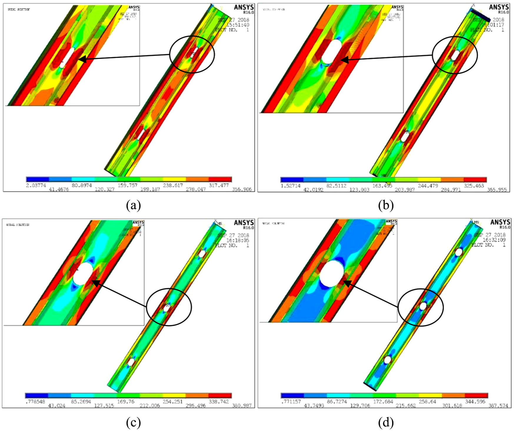
Typical von Mises stress distribution of perforated members at ultimate load: (a) DC2NL1200T2H0.5, (b) DC2NL1200T2H0.8, (c) DC2WL1800T1H0.8, and (d) DC2WL1800T1H1.
DSM of perforated built-up section specimens
Only single-limb channels with complex edge stiffeners and perforations under axial compression were studied at present (Wang et al., 2015). There were no definite DSM formulas for built-up I-section columns with complex edge stiffeners and perforations under axial compression. In this article, a total of 60 such built-up members were calculated by existing literature research methods in order to investigate its applicability.
Description of DSM
The DSM to predict the ultimate load of perforated members relied on the elastic buckling stresses, which can be obtained by means of rational elastic analysis, such as finite strip software CUFSM proposed by Schafer (Moen and Schafer, 2009). The elastic buckling analysis using the finite strip method requires the given section to be uniform along the longitudinal direction. However, the built-up I-sections connected by screws did not meet this requirement, and thus, the built-up I-sections cannot be directly employed for calculation in the finite strip method. At present, relevant scholars solved the above problem by simplifying the built-up member buckling model. Although the obtained elastic local buckling stresses of the model may be inconsistent with the actual value of the built-up I-sections, the effect of that method on the ultimate bearing capacity was still modest (Li et al., 2014; Lu et al., 2017). For built-up I-section specimens with perforations, the calculation of the critical elastic buckling stresses for local buckling (σcrl) and distortional buckling (σcrd) were based on the model assumption of single-limb members and the influence of holes was considered. According to the AISI code, when determining the flexure buckling stress (σcre) of the built-up columns, the modified slenderness method was specified. Its model was based on double-limb members and the influence of holes was also considered. And then the obtained elastic buckling stresses were input into exiting DSM design expressions for perforation (Moen and Schafer, 2011; Yao and Rasmussen, 2017a).
It can be seen from the comparison of two types of DSM formulas that the equations of overall buckling capacity (Pne, see equation (1)) and the local buckling capacity (Pnl, see equation (2)) were consistent. The formulas were as follows
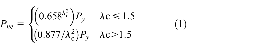
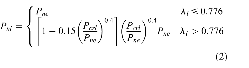
where
However, for the equations of distortional buckling capacity, the design expressions of Yao and Rasmussen (see equation (3)) included interaction with global flexural buckling, while that of Moen and Schafer did not (see equation (4)). Their formulas were as follows

where

where
The column capacity Pn was the minimum strength of Pne, Pnl, Pnd (or Pnde).
Calculation of DSM
In this study, a total of 60 perforated built-up I-section columns with complex edge stiffeners were selected. It is worth mentioning that the FEA results about DC1 members were added in Table 6. Since there were no web stiffeners in DC1 section, the ratio of hole depth to web (dh/H1) was defined as variables. The meaning of specimen label at the corresponding locations was also changed. Other section sizes and material properties were the same as those of the members in “DSM of perforated built-up section specimens” section. Correspondingly, comparison of the calculation and simulation results were listed in Table 6, in which the PD1 and PD2 were the results calculated according to the DSM design expressions of Moen and Schafer (2011) and that of Yao and Rasmussen (2017a), respectively. It was shown that the mean value of PD1/Puf was 1.09, and that of the PD2/Puf was 1.03. Their coefficients of variation were 0.120 and 0.107, respectively. Therefore, the calculation results obtained by using two types of methods were both valid for the perforated specimens studied in this article. In comparison, the PD2/Puf results were relatively closer to 1.00 than the PD1/Puf results.
Comparison of DSM calculation results and FEA results.
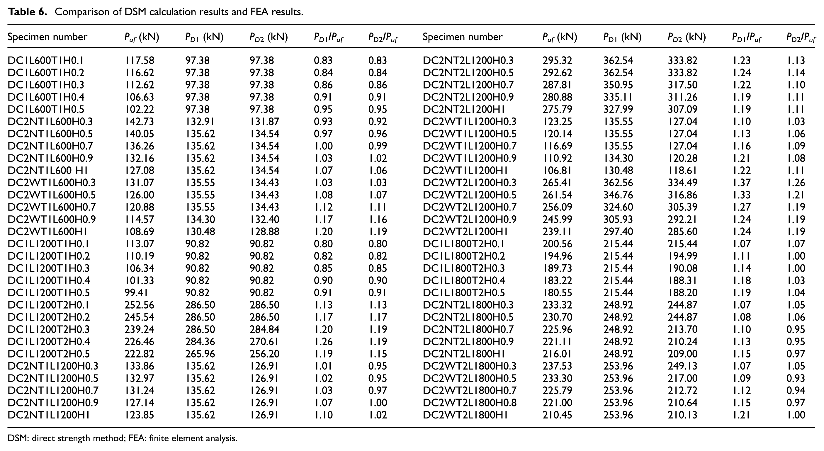
DSM: direct strength method; FEA: finite element analysis.
Conclusion
A total of 20 built-up columns with openings including 12 axial compression specimens and 8 eccentric compression specimens were tested and a series of parametric analysis work had been presented in this article. Based on above research, two types of DSM design expressions were used for the calculation of perforated built-up columns. The conclusions were summarized as follows.
Web stiffeners could control the local buckling of plates effectively and improve the ultimate bearing capacity of the built-up columns obviously. It made the distortional buckling become the governing failure mode.
Compared with DC1 members under the same conditions, the loading efficiency of DC2 members was increased about 2% to 32%. It indicated that the loading efficiency of short columns and medium-long columns could be effectively improved by the web stiffeners. However, for the long column, failure was mainly controlled by the overall flexural buckling mode. The stiffened web had little effect on the overall bending stiffness.
The buckling deformation around the hole of DC2 specimens was relatively smaller than that of DC1 specimens. This indicated that web stiffeners could restrict the deformation of plate around the hole. However, composite action of DC2 specimens between the single-limb webs was lower than that of DC1 specimens. Further research showed that the maximum stress of perforated DC1 member was concentrated at the flange and complex edge stiffeners. But for perforated DC2 member, it was also concentrated around the holes. The stress redistribution could be caused by longitudinal stiffeners and web holes.
For perforated Σ-shaped section built-up columns subjected to axial compression, the optimum ratio of hole depth to web sub-element (dh/H3) could be determined about 0.7–0.8. With the increasing of the hole depth, more loads were borne by the web stiffeners and the combination of flange and complex edge stiffener. It made distortional bucking happen easier.
The mean values of the calculation results obtained by adopting the two types of DSM design expressions for perforation were 1.09 and 1.03, respectively. The calculation results obtained by using two types of methods were both valid for the perforated specimens studied in this article.
Footnotes
Declaration of Conflicting Interests
The author(s) declared no potential conflicts of interest with respect to the research, authorship, and/or publication of this article.
Funding
The author(s) disclosed receipt of the following financial support for the research, authorship, and/or publication of this article: This investigation described in current paper was supported by Higher Education Innovation Talent support Program of Liaoning Province (LR2016032) and Natural Science Foundation of Liaoning Province (20180550665).