
Abstract
Experiments were performed to investigate the behavior of prismatic blocks with steel-fiber-reinforced reactive powder concrete subjected to centrally applied pressure in a limited area. The objective was to understand the reinforcement effect of orthogonal ties in reactive powder concrete anchorage zone. The three experimental variables were the volumetric ratio of the orthogonal ties, ranging from 4.63% to 5.83%; the ratio of the gross supporting area Ab to the bearing plate area Al (local area aspect ratio); and the ratio of core area Acor to the bearing plate area Al (core area aspect ratio). The steel-fiber ratio by volume was 2%. Block behavior in terms of cracking and crack width is related to the bridging effect of the steel fibers and the confining influence of the orthogonal ties. No visible crack and constant stiffness of the specimen prior to cracking were observed. Possible brittle failure was improved to ductile failure, as measured by appearance of major cracks on the sides and ends of the blocks. The orthogonal ties have distinct effect of confining the core of the reactive powder concrete when the ratio of the area of the bearing plate to the area of the reactive powder concrete core surrounded by the orthogonal ties exceeds 1.0.
Keywords
Introduction
Reactive powder concrete (RPC) has been developed as a green cement-based material that contains industrial wastes of silica fume and ground slag (Blais and Couture, 1999). Its main merits are the ultrahigh strength, excellent durability, and abrasion resistance, which make it possible to achieve slender, large-span structures of buildings, bridges, and ocean constructions. If RPC is used as a major material in post-tensioned structures, the ultrahigh compressive strength of RPC can be made full use of. Within the same structural design, a smaller cross-sectional dimension may be required for post-tensioned RPC members than for common post-tensioned members. Nevertheless, for the relatively small-dimensional RPC anchorage end, the pre-stressing force transferred through the anchorage plate as a concentrated force results in both a large magnitude of stress and its complex distribution in the region behind the anchorage plate. The distinct tensile stresses and their resultant force–bursting force tend to split the anchorage zone apart. Evidently, predicting the failure mechanism of the RPC anchorage zone is one of the major issues while evaluating post-tensioned RPC structures with small cross-sectional size. It is essential to analyze the bearing capacity and determine the detailing of the reinforcement in the design of the RPC anchorage zone.
Failure of non-fibered RPC specimens without transverse reinforcement, which are loaded monotonically into a limited area, occurs suddenly in a brittle manner. Generally, the effects of bursting and the spalling of failure split the specimens apart (Zhao, 2008). These undesirable failure characteristics potentially affect the RPC applied into the post-tensioned anchorage zone.
Orthogonal ties are generally placed in the anchorage zone of the post-tensioned structures to confine the concrete core, resist bursting stress, and enhance the bearing capacity. The confining effect of the reinforcement causes the concrete core to be in a state of three-dimensional stress and strain, thus increasing the ultimate compressive strength. In practice, the orthogonal tie is one of the major forms of reinforcement used in the post-tensioned anchorage zone (Ahmed et al., 1998; Komendant, 1952). Tests indicate that 12 non-fibered RPC blocks confined by orthogonal ties fail in an almost ductile manner. Cracking occurs prior to failure, and finite cracks develop slowly on the side surface. Pressure causes wider cracks and spalling at the loading surfaces. Low cracking load possibly would imply that the RPC anchorage zone with orthogonal ties would crack under the service load (Hu, 2012).
For specific construction projects in severe environments and the requirement of no visible cracking, the reliability may decrease due to possible cracking in the RPC anchorage zone if it is only reinforced by mild steel orthogonal ties. Hence, the widths of cracks need to be controlled to address the serviceability and durability of the post-tensioned anchorage zone. Meanwhile, transverse reinforcement arranged in the anchorage zone normally causes congestion and difficulty in casting concrete, and it is especially critical for small cross-sectional RPC end blocks. Adding steel fibers into a concrete mixture enhances the mechanical properties of non-fibrous concrete. It helps in enhancing the tensile strength due to its effect of bridging the cracks in the fibers, whereby the force is redistributed among the concrete and the steel fibers. Moreover, steel fibers play a role in inhibiting cracking and resisting material disintegration (American Concrete Institute (ACI), 1996; Haroon et al., 2006; Johnson, 2006). To decrease the risk of anchorage failure and increase the efficiency of construction, it is desirable to add steel fibers into the RPC anchorage zone.
Research significance
After enhancement of non-fibrous RPC by adding steel fibers and thereby producing steel-fiber-reinforced RPC, it is possible that the inhibition of cracking would improve the serviceability of the post-tensioned anchorage zone (by controlling cracks). Reinforcement with mild steel would also be decreased by adding steel fibers to avoid congestion of reinforcements, thus reducing casting difficulty. To investigate the mechanical properties of the RPC used in the anchorage zone and the feasibility of reducing steel reinforcement by incorporating steel fiber, the experimental RPC prism test that simulates the anchorage zone was conducted to validate the behavior of the end block. The enhancement caused by steel fibers and confinement by orthogonal ties were used to assess the failure mechanism and for calculating the bearing capacity. The major factors that influence the failure mechanism and bearing capacity were analyzed.
Test program
RPC mixture
RPC proportioning
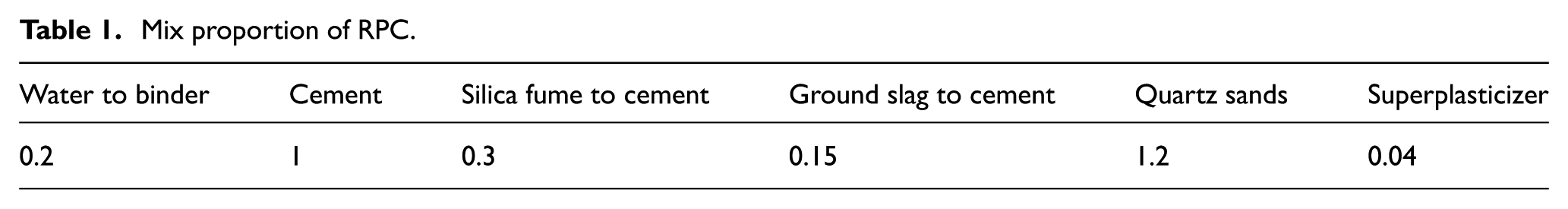
The proportion of the RPC mixture is shown in Table 1. The powders of the RPC contain Portland cement, silica fume, quartz sand, and ground slag. The SiO2 content in the silica fume is greater than 93%. The specific surface area of the ground slag is 4108 cm2/g. The SiO2 content is greater than 99.6% in the quartz sand, with the particle size distribution ranging from 40–70 mesh to 70–140 mesh. Steel fibers were added at 2% of the volume of the mixture.
Mix proportion of RPC.
Steel fiber
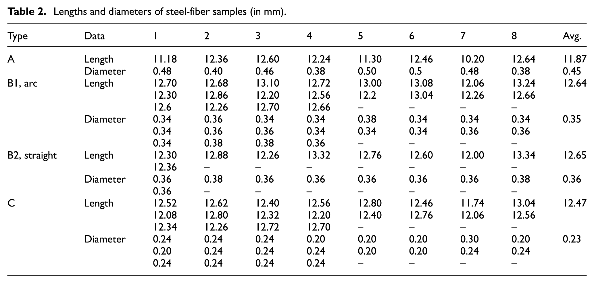
The steel fibers are short copper-plated straight slit wires. Randomly, 300 fibers were sampled to determine the following properties: length-to-diameter ratio and density. Observation shows that these fibers may be divided into three forms: (1) type A (8/300), contains three hair fiber strands; (2) type B (67/300), short and stiffer; and (3) type C (225/300), the main one which is soft and hair like. For type A, the lengths and diameters of all samples were recorded. For type B and type C, 29 out of 67 and 20 out of 225 were sampled randomly, respectively, as listed in Table 2. It indicates that the ratio of the average length to the average diameter ranges from 27 to 54. The minimum diameter of the fibers is 0.2 mm, and the maximum diameter is 0.5 mm, as shown in Figure 1(a). According to Archimedes’ laws of buoyancy, the average density of the steel fiber tested was 8.73 kg/m3. The average tensile strength of the steel fiber was 2800 N/mm2.
Lengths and diameters of steel-fiber samples (in mm).

Specimen fabrication: (a) steel fiber, (b) mixing, (c) casting, and (d) compacting by vibrating.
RPC fabrication
A total of 12 specimens were cast at the same time, using the same mix. A special casting method, in which different materials were added to the mixture in different batches, was used for specimens with 2% steel fibers by volume. All the powders were mixed in a countercurrent mixer for the first 3 min. In the following 5 min, water and superplasticizer were added to the mixer. Then, steel fibers were added gradually at the last 2 min, and the RPC mixture was cast into the mold of the specimen, then the RPC mixture was compacted by vibrating for 30 s using a mechanical vibration generator system, as shown in Figure 1. After all the RPC specimens were cast and compacted, the specimens were kept still indoors (25°C, 80% relative humidity (RH)) for 48 h. Subsequently, steam curing was conducted in an autoclave. All specimens were heated for 8 h in the autoclave in a vapor-saturated atmosphere at an ultimate temperature of 140°C and 6.7 atm (0.676 MPa). Ambient curing was performed indoors for 28 days.
Properties of materials
RPC
RPC cubes with dimensions of 100 × 100 × 100 mm3 and test prisms of 150 × 150 × 300 mm3 were cured together with the test specimens. Overall, 15 cubes and 15 prisms were used to test the strength and elastic modulus of the RPC, respectively. The specific compressive strength of RPC was tested, as shown in Figure 2. The mechanical properties derived were as follows: the average cubic compressive strength was 157.2 N/mm2, the prismatic compressive strength was 94.3 N/mm2, and the elastic modulus was 3.789 × 10⁴ N/mm2. The tensile strength was 9.7 N/mm2, which was calculated following the theory proposed by Li (2010).

Testing of the specific strength using the 100-mm cube.
The dimensions of test cubes (100 × 100 × 100 mm3) and prisms (150 × 150 × 300 mm3) used in this study for steel-fiber RPC were the same as the ones for ordinary concrete, which were bigger than the test samples in some other literature. It was the size effect that led the cubic compressive strength seemed small and the prismatic compressive strength was only 60% of the cubic compressive strength.
Orthogonal tie
For the mild steel used for orthogonal tie, the yield stress was 408 N/mm2, the ultimate tensile stress was 535 N/mm2, and the elastic modulus was 2.0 × 10⁵ N/mm2.
Specimen parameters and testing
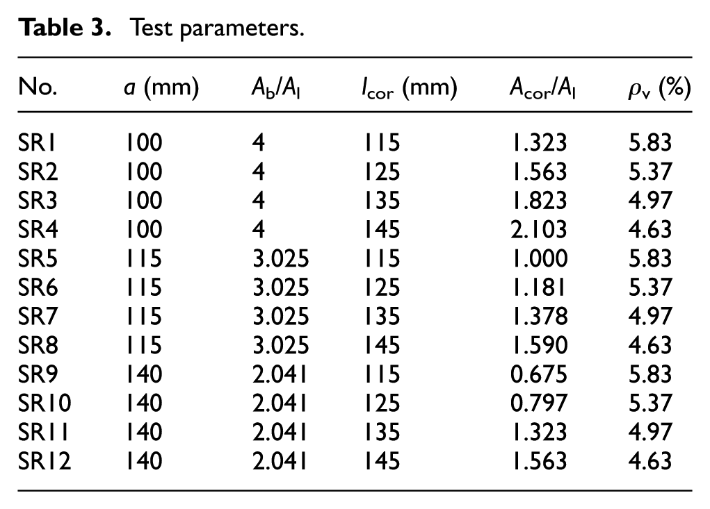
In total, 12 specimens were tested with 3 factors: local area aspect ratio
Test parameters.
Small-valued local area aspect ratio (
Although the size and geometrical dimensions of the test specimens are known to affect the test results, the loading capacity of the mechanical machine controls the ultimate load that may be applied in the experimental specimens, and this is a main factor that is used to determine the cross-sectional sizes. In addition, based on the Saint-Venant principle, the local pressure extends along the tendon axis from the bearing plate to the length equal to the sectional depth in the anchorage zone. Conservatively, each specimen is a prismatic RPC block that simulates a post-tensioned anchorage zone, and the dimensions of its cross-sectional depth, width, and height are 200, 200, and 400 mm, respectively. A circular duct with a diameter of 50 mm is placed in the center along the longitudinal axis of the prism, which can arrange five tendons with a maximum diameter of 15.2 mm in the circular duct. The three bearing plates are all squares, with edge sizes (a) of 100, 115, and 140 mm, which have local area aspect ratios
Test results on ordinary concrete reinforced by ties indicate that the core area aspect ratio (i.e. the ratio of the horizontal area of the concrete core enclosed by orthogonal ties
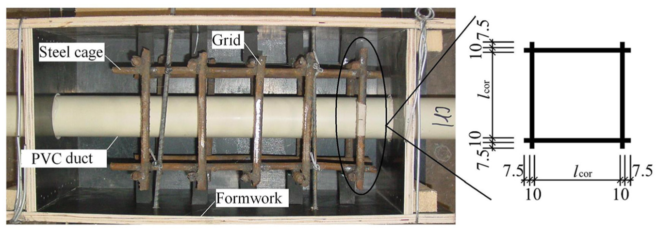
Grids in the formwork and the locations of the strain gauges (in mm).

Details of grids and strain gauges: (a) arrangement of steel grids (bearing plate size and steel cage of specimens SR1) and (b) strain gauges in the steel grids.
Test setup
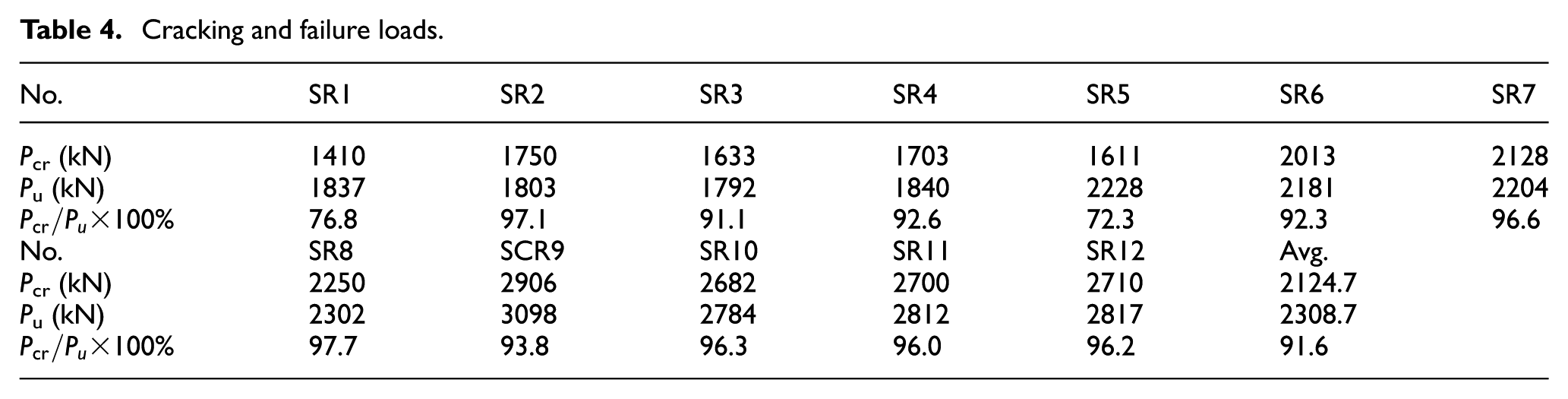
In the multistage loading program using the static setup shown in Figure 5, the load step was 10% of the estimated failure load. The estimated failure load was calculated following code GB 50011-2010 for reinforced concrete structures. Cracking was recorded for any hairline crack observed on the side surface of the specimen, and the peak value of the testing curve of load versus deformation was considered as the failure load; these test values are shown in Table 4.

Setup used in the test.
Cracking and failure loads.
Eight linear variable differential transformers (LVDTs) were arranged to record different deflections. LVDTs 2 and 4 recorded the depression in loading surface caused by the bearing plate,
Observations and results
Propagation of cracks
Before a load of 70%–90% of the failure load,

Effects of (a)
Due to the possible slippage of the steel fibers and the occurrence of inner micro-cracking, a continuous stubble sound emanated during the loading procedure. Cracks were initially found on the side surface of the prismatic specimen, and their development and characteristics include the following features: (1) crack was found on not more than three surfaces for each specimen; (2) not more than three cracks developed on each surface; (3) once cracking was initiated, vertical or inclined cracks mainly developed on the upper half of the surface, and no cracks propagated longitudinally near the height throughout their extensions before failure; (4) most of the cracks were thicker in the middle part than in both ends; (5) the maximum width of the initial cracks was generally located at a distance from the loading surface equal to the length of the edge of the bearing plate (approximately located at the wedge tip); (6) most of the specimens observed had an effective crack width not more than 0.3 mm; (7) some cracks had large width while cracking, for example, the maximum value being 0.4 mm for specimen SR1 and 0.3 mm for SR2; (8) several initial cracks extended discontinuously, that is, they could disappear along their extensions; (9) from cracking to failure, initial cracks generally were in a stable state, and their width and extension remained almost unchanged, even though the external load was close to the failure load; and (10) close to failure, new thin cracks could appear alongside the initial cracks, and their maximum width was not larger than their initial width.
Close to the peak load, new cracks suddenly appeared on the lateral surfaces; meanwhile, more cracks dramatically developed on the loading surface. Splitting cracks or splitting tendency could be observed for the specimens. Their characteristics include the following: (1) for 3 of 12 specimens, cracks were found on 3 side surfaces, and no crack was found on the fourth surface; for 9 other specimens, cracks developed on all 4 surfaces; (2) the initial part of cracks on the side surfaces of the invariable specimen suddenly extended and widened to develop as main cracks, that is, the width of the main crack was far more than that of other cracks, and the maximum width of the main cracks of the side surface was 7 mm; (3) similar main cracks appeared on the loading surface, and the maximum width was 8 mm; (4) numerous radial cracks, including the main cracks, and other irregular thin cracks appeared around the bearing plate on the loading surface; (5) the upper end of the main cracks of the side surfaces was correspondent to that of the loading surface; (6) totally, the maximum value of the cracks was larger than that of the side surfaces; (7) splitting or splitting tendency could be found for different specimens, and some specimens lost their local corner due to splitting; and (8) the main cracks resulted in severe damage due to splitting.
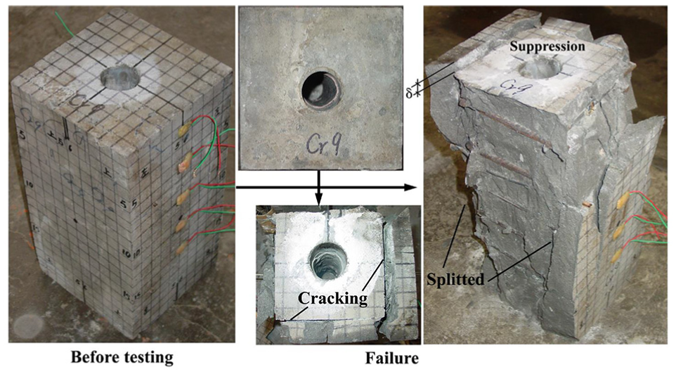
Failure characteristics
The failure mode involves splitting or splitting tendency followed by cracking, that is, the cracking load is close to the failure load. The ratio of the cracking load to the failure load of 10 prisms, excluding SR1 and SR5, exceeded 90%, as indicated in Table 4. The major failure characteristics, as shown in Figures 7 and 8, include depression in loading surface caused by the bearing plate, and corner cracking, radial wide cracks, or splitting cracks occurring on the loading surface. It can be inferred that the hidden pyramid wedge appeared adjacent to the bearing plate (Ince and Arici, 2004; Meyerhof, 1953; Niyogi, 1973, 1974).

Cracks or splits at the loading surface at failure: (a) SR1, (b) SR2, (c) SR3, (d) SR4, (e) SR5, (f) SR6, (g) SR7, (h) SR8, (i) SR9, (j) SR10, (k) SR11, and (l) SR12.

Failure characteristics of RPC with steel grids: (a) specimen SR1 and (b) specimen SR9.
Results and observation show that two factors may affect failure behavior. The first factor is the local area aspect ratio,
The secondary factor that affects the failure characteristics is the core area aspect ratio,
Because the steel fibers bridge the cracks and absorb the deformation energy, all the specimens remained integrated, as shown in Figure 8. There is a distinct discrepancy in the failure behavior for non-fibrous versus fibrous specimens. Failure of the non-fibrous RPC specimens occurred suddenly with splitting and spalling, even though both specimens were reinforced with identical steel grids, as shown in Figure 9 (Hu, 2012).
Splitting and spalling of non-fibrous RPC with steel grids (Hu, 2012).
Load versus deformation
Figure 10 shows a typical relationship between the local load P and the various deformations
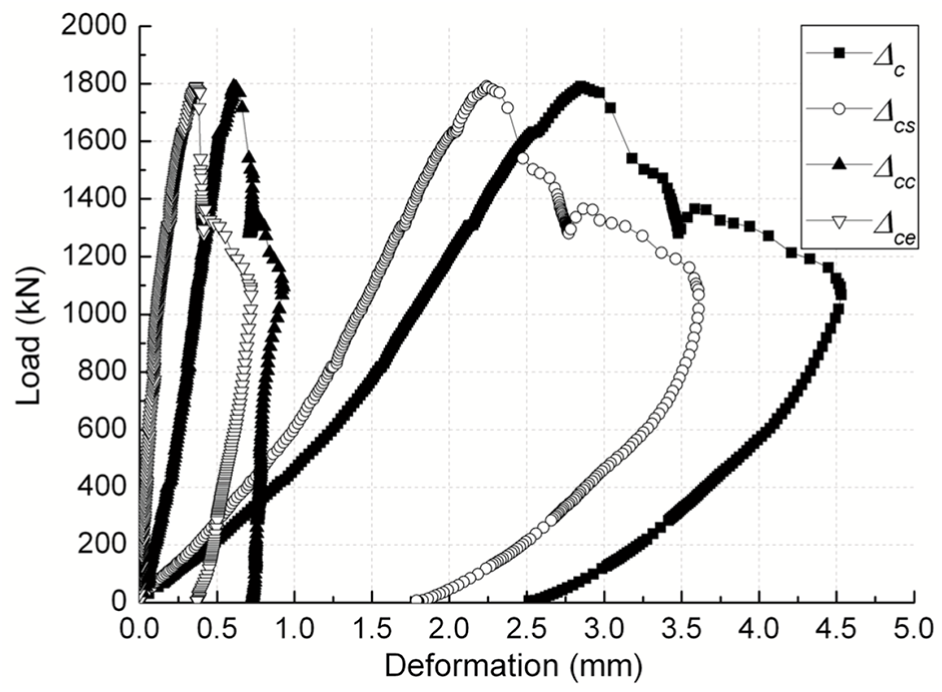
Load versus deformations of a typical specimen (SR3).
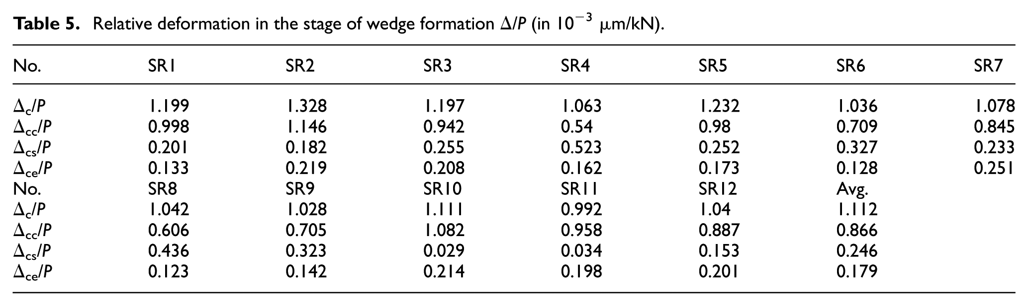
Relative deformation in the stage of wedge formation Δ/P (in 10−3 μm/kN).
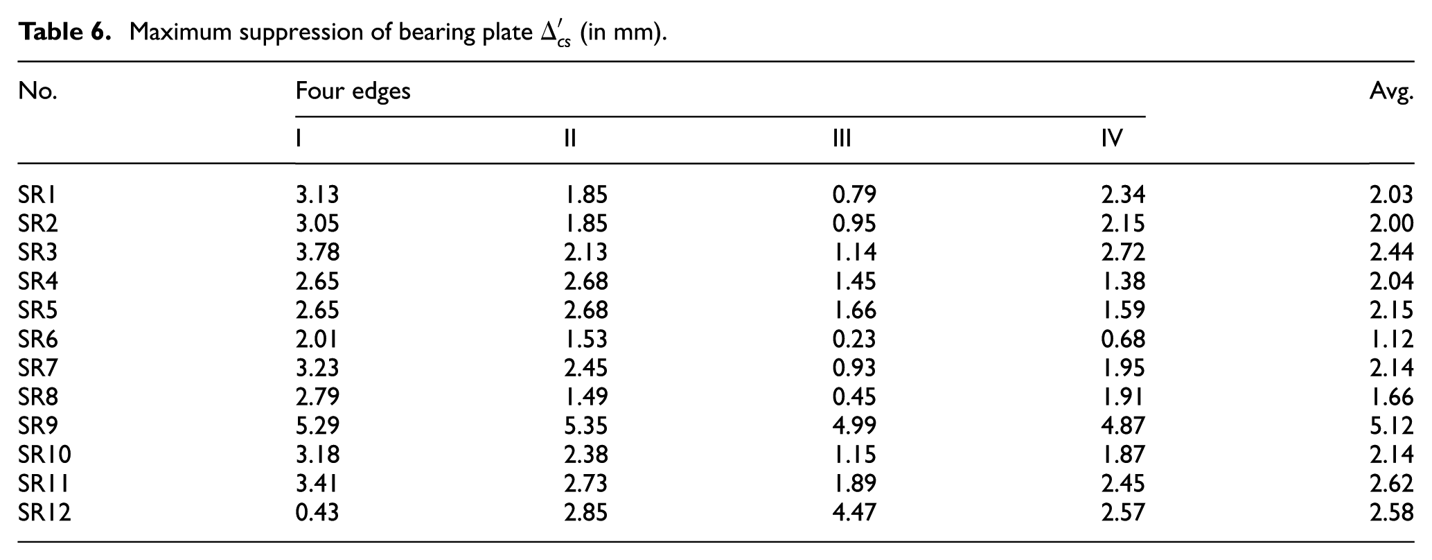
Maximum suppression of bearing plate
Steel strains
Based on the material properties, the yield strain of the steel ties was 0.002. At failure, only 58.33% (7 of 12) of the specimens reached yield stress. Regarding the other 41.67% (5 of 12) of the specimens, from loading to failure, the strains of the steel ties increased evidently within a certain height for all specimens but cannot reach the yield stress at failure. The strains of steel ties within a certain height reached 0.0015 at least (the stress was about 300 N/mm2) for 80% (4 of 5) of these specimens at failure, thus 0.0015 was specified as the approximate yield stress of the steel tie for all 12 specimens. At failure, the average stress of the ties in 91.67% (11 of 12) of the specimens exceeded the approximate yield stress. Thus, effective confinement appeared in almost all of the specimens. In the 11 specimens exceeding the approximate yield stress, there were 10 specimens with a value of
No evident relationship was found between the location and the yield stress of a steel grid, as shown in Figure 11. The steel yield stress was recorded in all the gauges for the various specimens. At a depth of 215 mm, 11 specimens were found to exceed the approximate yield stress. At depths of 95 and 155 mm, 10 specimens were found to exceed the approximate yield stress. For the 35-mm location, the number of specimens exceeding the approximate yield stress was five. Only one specimen showed yield stress at a depth of 275 mm. Prior to the wedge slippage, steel strain developed slowly with an increase in the external loads, and the slope increased rapidly with the load level before failure. The relationship between the external load and the strains of the ties is shown in Figure 12.
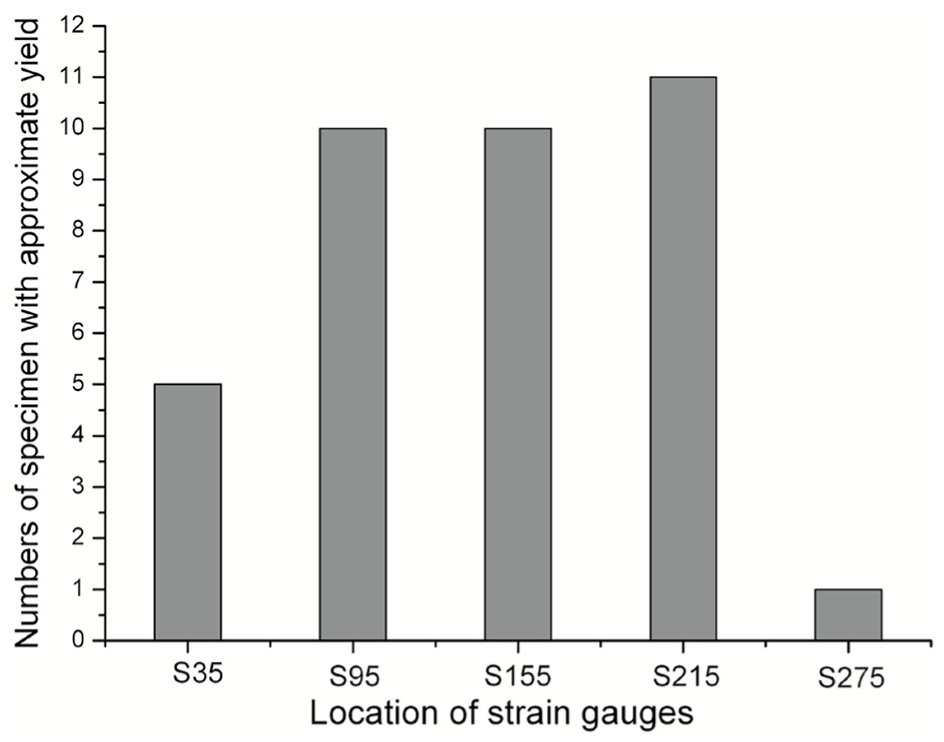
Number of approximate yield measurement points and their location.
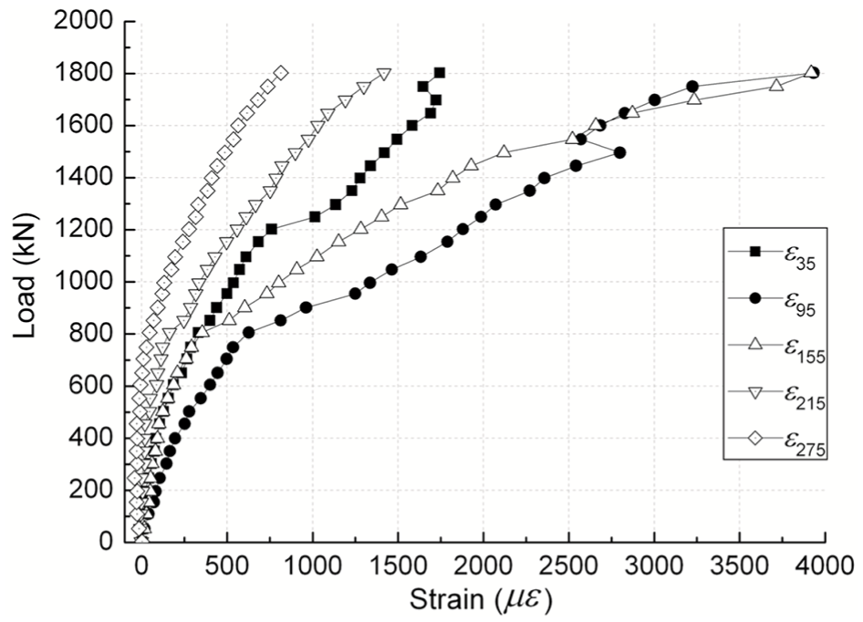
Load versus steel strain of a typical specimen (SR2).
Discussion
Failure of the prism under local pressure is due to the development of a wedge ahead of the splitting of the bearing plate that surrounds the RPC, which is confined by orthogonal ties. In this wedge, the strengths of both the confining concrete and the steel grid influence the splitting failure. If the core area aspect ratio
The high compressive stresses around the bearing plate and the tensile stresses in the anchorage zone should be the focus of the analysis of an RPC prism under local pressure. Orthogonal ties are placed in the anchorage zone to provide confinement for the RPC so that it bears high compressive stresses; the bursting stress should be estimated and skin reinforcement be used to resist the tensile stresses. In practice, these reinforcements are used to increase the bearing strength of the anchorage zone. Previous tests have demonstrated that steel fiber may be added to the concrete in the anchorage zone to partially replace or reduce the steel reinforcement (Zhou and Hu, 2013). Consequently, it is necessary to consider the enhancement of the bearing capacity of the RPC by addition of steel fibers.
Conclusion
From this study, the following conclusions can be drawn:
Integration of the block to some extent at failure was guaranteed when steel fibers were added to RPC. No visible crack was observed in service load. Stiffness of the specimen in the stage of wedge formation was constant prior to cracking (in the service load).
Combining the bridging effect of the steel fibers and the confining influence of the orthogonal ties, the bearing failure mechanism was improved from a possibly brittle failure mechanism to a ductile failure mechanism. At failure, only two or more major cracks appeared on the corner of the loading surface, and the extent of the deformations, including middle expansion and vertical compression, was not evident, excluding the suppression after separation of the bearing plate.
The orthogonal ties had the distinct effect of confining the core of the RPC when the ratio of the area of the bearing plate to the area of the RPC core surrounded by orthogonal ties exceeded 1.0.
A total of five orthogonal ties positioned over the range of distance from the loading surface to 1.55 times of the sectional depth reached the yield stress for various specimens. This result implies that the entire zone of the RPC core surrounding the steel cage is influenced by local pressure.
Footnotes
Declaration of Conflicting Interests
The author(s) declared no potential conflicts of interest with respect to the research, authorship, and/or publication of this article.
Funding
The author(s) disclosed receipt of the following financial support for the research, authorship, and/or publication of this article: This research was funded by the National Natural Science Foundation of China (no. 51778186).