



Abstract
The mechanical properties of the viscoelastic damper made of high damping rubber produced in China are investigated in order to provide the basis for its application. At first, the test on material properties of high damping rubber is conducted. The Mooney–Rivlin model, the Yeoh model and the Prony series are applied for simulating the nonlinear behavior of the high damping rubber with the aid of software ABAQUS. Then, three viscoelastic dampers with different sizes are tested under cyclic loading. The effects of strain amplitude and loading frequency on hysteretic behavior of dampers are analyzed. Viscoelastic dampers possess large deformation capability, stable energy-dissipation capacity and good fatigue-resisting property. The effect of strain amplitude is much more significant than loading frequency. The hysteretic behavior of the dampers is simulated by the Bouc–Wen model and the model of the equivalent stiffness and damping, respectively. The prediction results by using the Bouc–Wen model are in good agreement with the experimental results, which indicates that the Bouc–Wen model is applicable to simulate the mechanical properties of high damping viscoelastic dampers with a wide range of shear strain. As to the model of equivalent stiffness and damping, it has the advantages of clear concept and simple calculation. However, the good accuracy of prediction can be obtained only when the shear strain is not greater than 60%.
Keywords
Introduction
Previous strong earthquakes around the world caused enormous loss of human lives and destruction to engineering structures. In order to improve the seismic performance of structures, various kinds of energy dissipation devices have been developed and installed in different types of structures in the past several years (Deng et al., 2018; Palmeri and Muscolino, 2011; Sun and Chen, 2015; Wang et al., 2018). In general, energy dissipation devices can be classified into the following types: metallic damper, viscoelastic damper, viscous damper, friction damper and intelligent material damper (Lu et al., 2012; Sun et al., 2017; Wen, 1976; Zhang et al., 2016). Among these dampers, viscoelastic dampers have been widely investigated and applied in the control of structural vibration. Compared with the metallic damper, the viscoelastic damper has the advantage of dissipating seismic energy in small vibration amplitude. In addition, compared with the viscous damper, the viscoelastic damper can provide bigger additional stiffness to the structure.
Viscoelastic dampers have been applied in civil engineering since 1960s. The first application of viscoelastic damper for earthquake resistance was the retrofit of a 13-story moment-resisting steel frame structure in Santa Clara County in 1994 (Crosby et al., 1994). Since then, a large number of researchers investigated the mechanical properties of the viscoelastic damper. Chang et al. (1997) performed a series of tests on the viscoelastic dampers. The effects of strain amplitude and loading frequency were investigated. Guo and Christopoulos (2016) examined the dynamic mechanical properties of viscoelastic material and proposed the theoretical calculation formula to determine the mechanical parameters of viscoelastic damper. Furthermore, the shaking table tests on a 1/4-scaled nine-story moment-resisting steel frame structure installed with viscoelastic dampers were conducted to evaluate the seismic performance of these dampers by Aiken et al. (1998). The optimal design method for the moment-resisting steel frame structure installed with viscoelastic dampers was proposed by Castaldo and De Iuliis (2014). A new viscoelastic coupling damper to enhance the wind and seismic performance of high-rise buildings was developed by Christopoulos and Montgomery (2013) and Montgomery and Christopoulos (2014). The nonlinear modeling of MDOF (multiple degrees of freedom) structures equipped with viscoelastic dampers was proposed by Ghaemmaghami and Kwon (2018). The analytical models for capturing the mechanical properties of the viscoelastic damper which have been proposed include Maxwell model, Kelvin–Voigt model, and the combinations of the above two models (Dargush and Sant, 2005; Kasai et al., 2010; Lewandowski and Chorążyczewski, 2010; Moreschi and Singh, 2003; Yamamoto and Sone, 2014). However, most of the previous research focused on the dampers with normal damping, and few studies have been carried out on high damping viscoelastic damper.
In this article, the viscoelastic dampers made of high damping rubber with larger deformation capacity produced in China are investigated by experimental study and numerical simulation. First, the test on material properties of high damping rubber is conducted, and the Mooney–Rivlin model, the Yeoh model and the Prony series are applied for simulating the nonlinear constitutive model of high damping rubber with the aid of software ABAQUS. Then, low-cycle cyclic loading tests are conducted on three viscoelastic dampers with different sizes. The hysteretic behaviors of viscoelastic damper are analyzed at different frequencies and strain amplitudes. Finally, the article also demonstrates a comparative study of Bouc–Wen model and the model of equivalent stiffness and damping by simulating the hysteretic behaviors of this damper. The research findings can be referred for the engineering application of high damping viscoelastic dampers.
Material property tests on high damping rubber
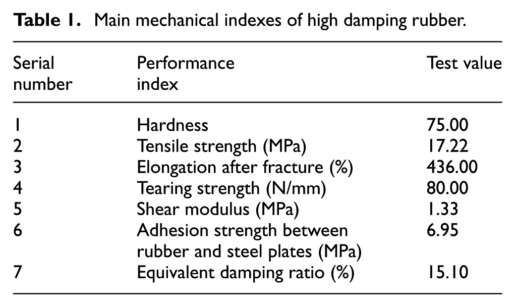
The dynamic properties of viscoelastic dampers are determined by the material properties of the viscoelastic material. A kind of high damping rubber made in China is used as the viscoelastic material in the damper in this study. Material property tests on the high damping rubber are conducted. The configuration of the specimen is shown in Figure 1. The red parts represent high damping rubber, and the gray parts represent the steel plates. The length, width and thickness of the high damping rubber are 25 mm, 25 mm and 6 mm, respectively. The rubbers bond with three steel plates. The length, width and thickness of the three steel plates are 100 mm, 25 mm and 6 mm, respectively. The loading of the specimens is displacement control. The displacement amplitudes are 6 mm, 12 mm, and 18 mm, respectively. At each amplitude, the specimens are loaded with four cycles. The damping force of the rubber at each level of displacement is recorded by the computer acquisition system. The main performance indexes derived from the tests are shown in Table 1. It can be found that the rubber owns high shear deformation capacity and high damping ratio as expected, and the material properties meet all requirements for engineering application. The hysteresis curves obtained by the test are shown in Figure 2. The shapes of hysteresis curves are ellipse when the deformation amplitude is 6 mm. When the shear deformation reaches 12 mm, the pinching effect becomes apparent due to the hardening of viscoelastic materials under larger deformation. The curves are inverse S-shaped.
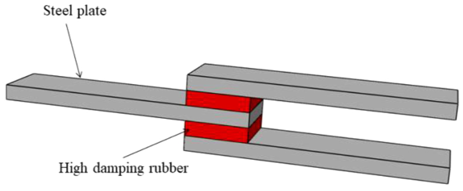
Configuration of the rubber specimen.
Main mechanical indexes of high damping rubber.

Hysteresis curves of high damping rubber.
Numerical simulation of the constitutive model of the high damping rubber
In ABAQUS, the simulation of the constitutive model of viscoelastic materials is based on the generalized Maxwell model that includes both the hyperelastic constitutive model and the viscoelastic constitutive model. The amplitude correlation of the generalized Maxwell model needs to be considered by manual modifying the parameters of the constitutive model for viscoelastic material under different strain conditions. The method for identifying the parameters of constitutive model is investigated in this study.
Model building
The ABAQUS/Standard analysis module is applied for modeling. The mesh types of the connection steel plate adopt eight-node linear hexahedron elements with reduced integration (C3D8R). The sweeping technique and advancing font algorithm are used to perform meshing. The finite element model is shown in Figure 3. The upper and lower plates of the model are completely fixed, and the middle plate is coupled with a reference point RP-1. The reference point RP-1 is subjected to step-by-step incremental cyclic displacement along the longitudinal direction of steel plate. The loading protocol is the same as the material test protocol.
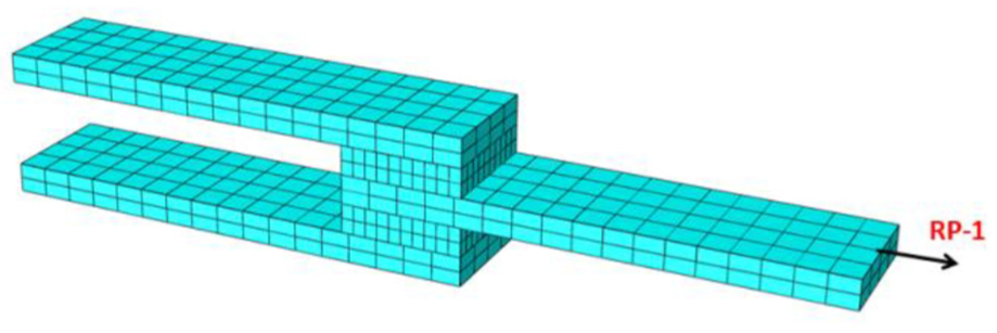
Finite element model of specimen.
Hyperelastic constitutive model
The polynomial form of the hyperelastic constitutive model is expressed as follows

where U is the strain energy potential,
When

For the polynomial form of the hyperelastic constitutive model, if n = 1, only the linear part of the strain energy remains, and the Mooney–Rivlin constitutive model can be derived as

For the reduced polynomial model, if n = 1, the Neo-Hookean constitutive model can be derived as

The Yeoh constitutive model is a special form of the reduced polynomial model for the case that n = 3 as follows

In the hyperelastic constitutive model, the mathematical relationship of stress

For the above several constitutive models, the Mooney–Rivlin model and the Yeoh model are applied for the simulation of constitutive model of high damping rubber in this research. It is assumed that the rubber is an incompressible and isotropic material with the Poisson’s ratio
According to equations (3) and (6), the Mooney–Rivlin model can be expressed as

According to equations (5) and (6), the Yeoh model can be expressed as
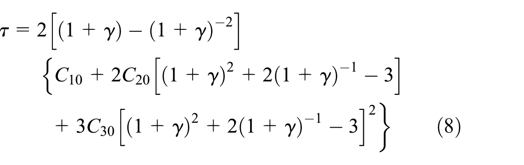
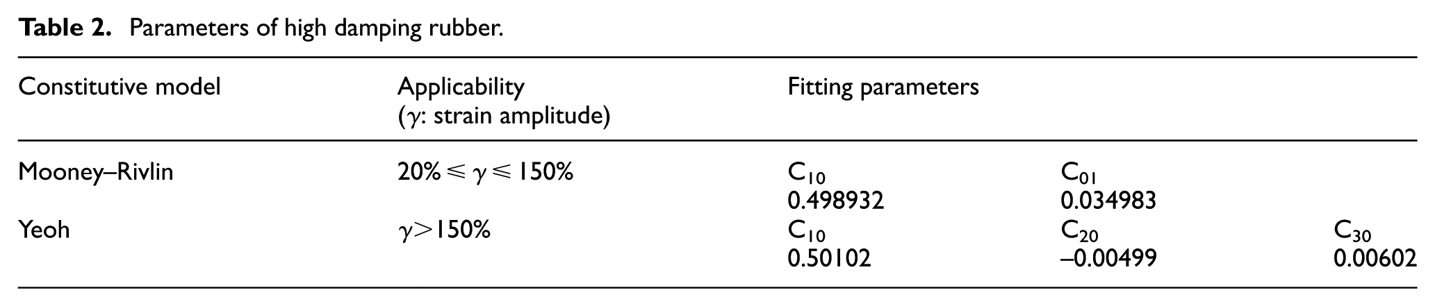
The parameters of the constitutive model for the high damping rubber as shown in equations (7) and (8) are obtained by the fitting of the test results. The parameters derived are shown in Table 2, which are only suitable for the rubber applied in this study.
Parameters of high damping rubber.
Viscoelastic constitutive model
Viscoelastic materials can exhibit creep under constant stress and exhibit stress relaxation at constant strain. In order to describe this viscoelastic behavior, the mechanical properties of the rubber material can be defined by the Prony series in ABAQUS. The shear modulus in this series is expressed as follows

where
According to the input hyperelastic and viscoelastic material parameters, the simulated hysteresis curves of the viscoelastic material can be obtained by ABAQUS. The comparison between the simulated results and the test results is shown in Figure 4. It can be seen that the simulation results are good agreement with test results, which validates the feasibility of the proposed simulation methods.
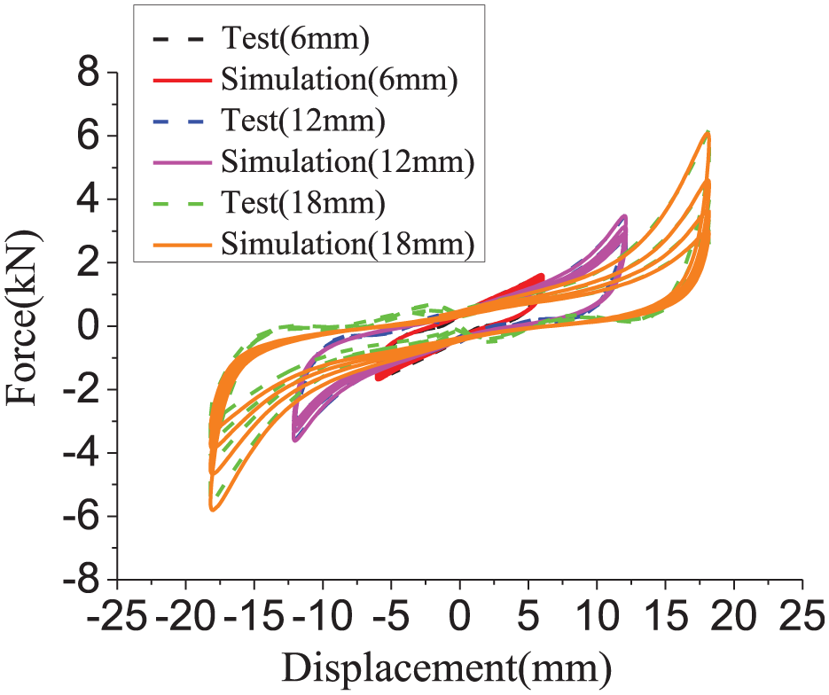
Comparison between the test curves and the simulation curves of high damping rubber.
Tests on viscoelastic dampers
As shown in Figures 5 to 7, three full-scale specimens of viscoelastic dampers, named S-A, S-B and S-C, were manufactured by the vulcanization bonding of two high damping layers with steel plates in parallel. The thicknesses of high damping rubber in S-A, S-B and S-C are 16 mm, 10 mm, and 10 mm, respectively. The diameters of all connection bolts are 24 mm. The mechanical properties tests were conducted. In addition, a hot air blower was utilized to create the desired environmental temperature. The environmental temperature was kept at 21°C to 25°C without consideration of the influence of temperature change. Hence, only the effects of loading frequency and strain amplitude on the viscoelastic damper are studied.
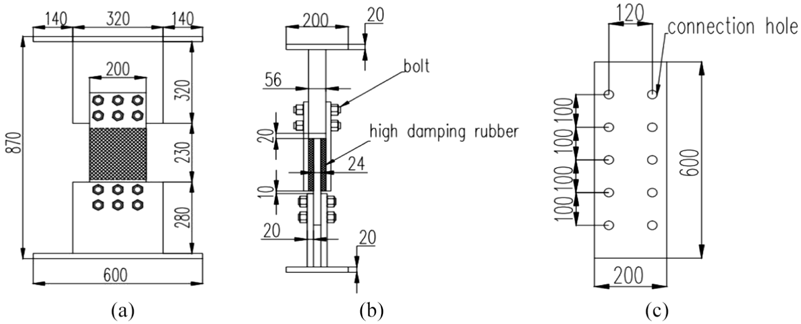
Configuration and dimensions of viscoelastic damper S-A (unit: mm): (a) Front view, (b) side view and (c) overhead view.
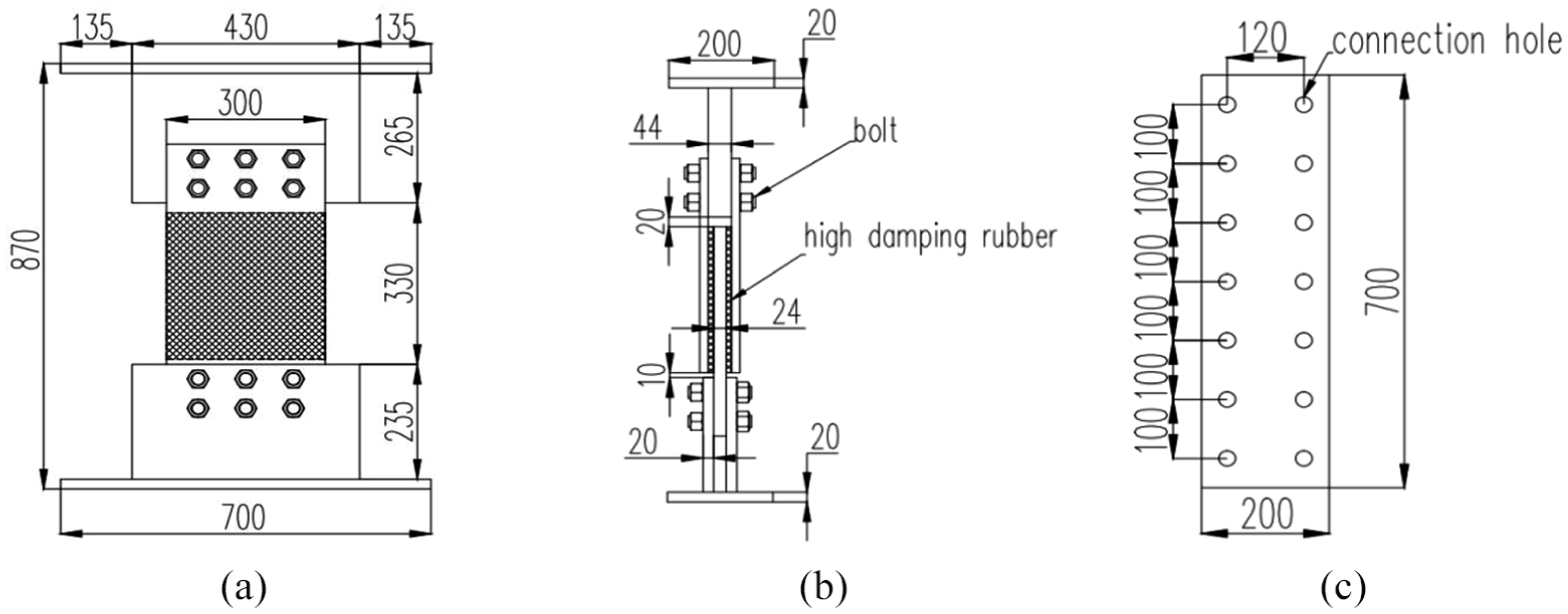
Configuration and dimensions of viscoelastic damper S-B (unit: mm): (a) Front view, (b) side view and (c) overhead view.
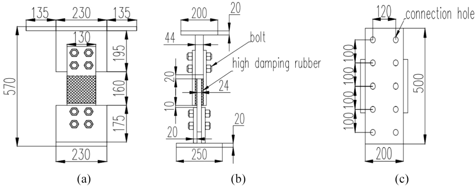
Configuration and dimensions of viscoelastic damper S-C (unit: mm): (a) Front view, (b) side view and (c) overhead view.
The test setup is shown in Figure 8. The cyclic horizontal load is applied by the MTS electro-hydraulic servo actuator. The loading is controlled by the displacement.
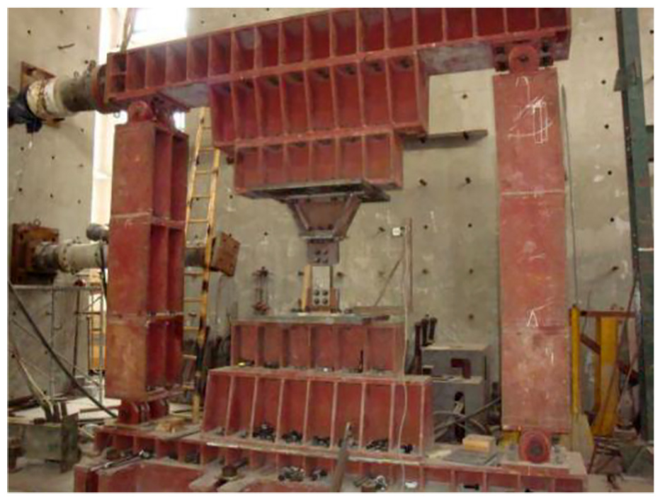
Test setup.
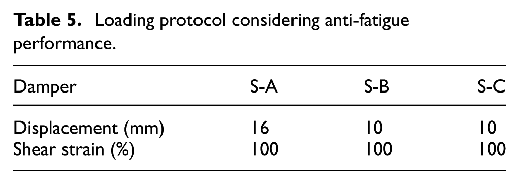
Each damper was loaded by three different loading protocols as shown in Tables 3 to 5 to investigate the effects of loading frequency and strain amplitude, and the anti-fatigue performance, respectively. In the first loading protocol for all dampers, five loading frequencies ranging from 0.1 to 0.5 Hz were considered. Due to limitation of the testing facility, large shear strain is not allowed when the loading frequency reaches 0.5 Hz. Therefore, the strain amplitudes of 60% and 80% were applied in the test. In the second loading protocol, different shear strain amplitudes were adopted for different dampers, and the loading frequency is 0.1 Hz. In the above two loading protocols, the dampers were subjected to five cycles of harmonic, displacement-controlled repeated loading at each amplitude. In the third loading protocol the shear strain amplitude was kept constant, and all dampers were loaded by 30 cycles.
Loading protocol considering effect of loading frequency.

Loading protocol considering effect of shear strain amplitude.
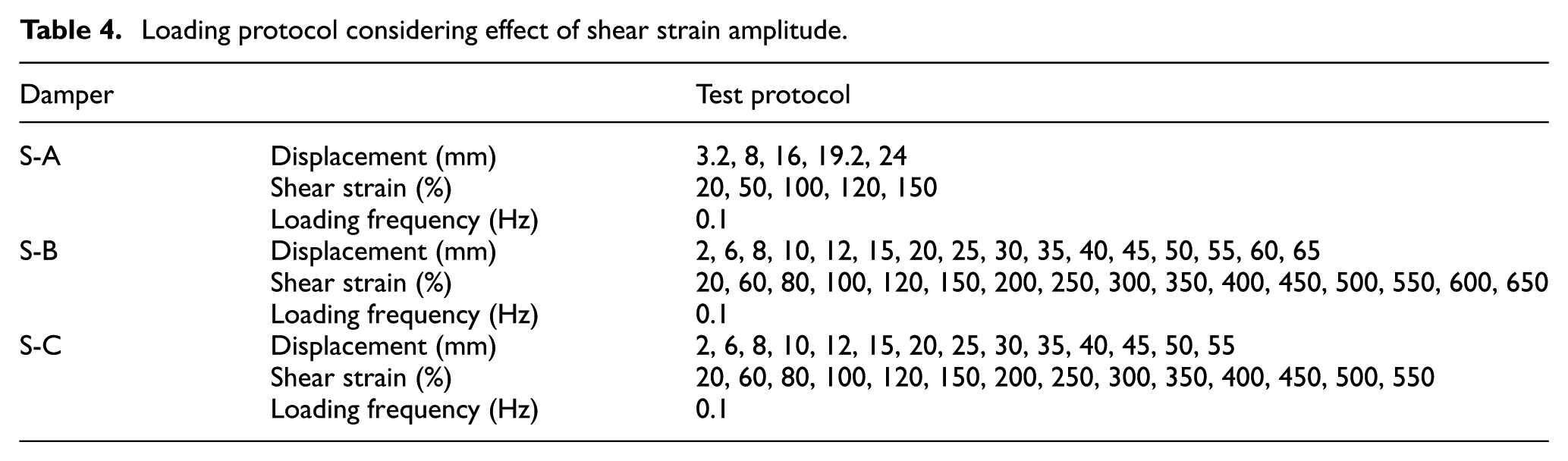
Loading protocol considering anti-fatigue performance.
Experimental results and analysis
Experimental phenomenon
Figure 9 shows the condition of three viscoelastic dampers. In the whole loading process, the high damping rubber layers of the damper S-A were bonded with the restrained steel plates tightly, and the high damping rubber layers had no residual deformation. Considering that the damper S-A would be used in another test for other research purpose, the shear strain was only loaded to 150% to prevent its damage in this test.
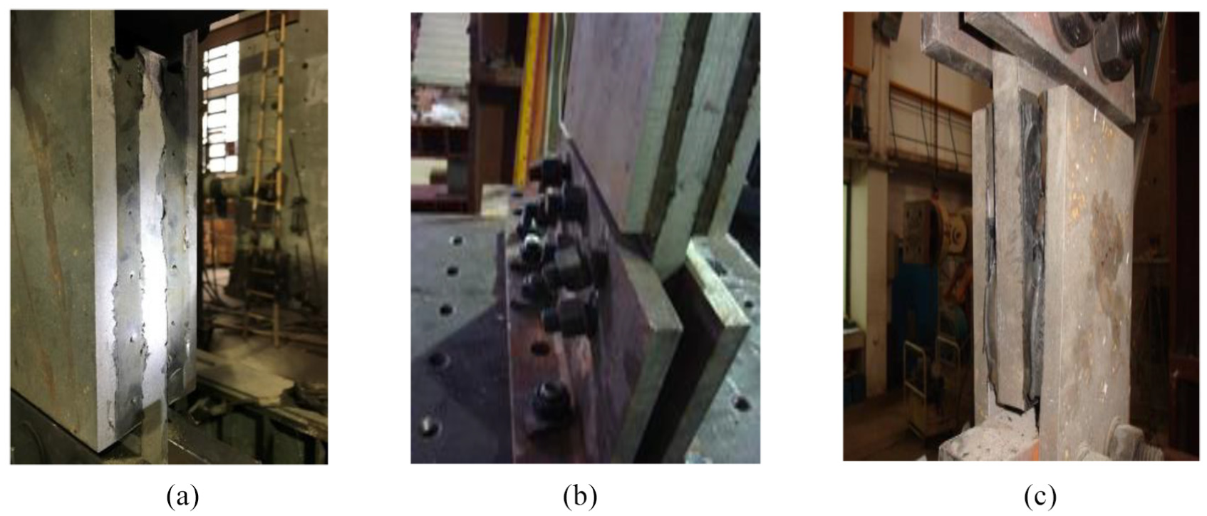
Experimental pictures of the viscoelastic dampers: (a) S-A with 150% shear strain, (b) S-B with 650% shear strain and (c) S-C with 550% shear strain.
When the shear strain of the damper S-B reached 300%, the high damping rubber layers had slight tearing damage. As the shear strain reached 650%, the connection bolts broke, and the viscoelastic material layers stripped from the restrained steel plates slightly.
As to the damper S-C, the high damping rubber layers stripped from the restrained steel plates significantly, and the damper presented tearing failure when the shear strain was up to 550%.
Effect of loading frequency on the mechanical properties of high damping viscoelastic dampers
Figure 10 shows the hysteresis curves of high damping viscoelastic dampers S-A, S-B and S-C at different loading frequencies. The test results demonstrate that the hysteresis curves are nearly coincident at different loading frequencies. The enveloping area and the tilt angle of the hysteresis curves change slightly when the excitation frequency increases, which indicates that the hysteretic behavior of viscoelastic dampers is less affected by the loading frequency and the energy dissipation capacity is stable. However, it can be seen that the shape of the hysteresis loops of S-B shown is different from that of S-A and S-C. The reason may be that in S-B the bolts which connect the steel plates slipped slightly in the loading process.
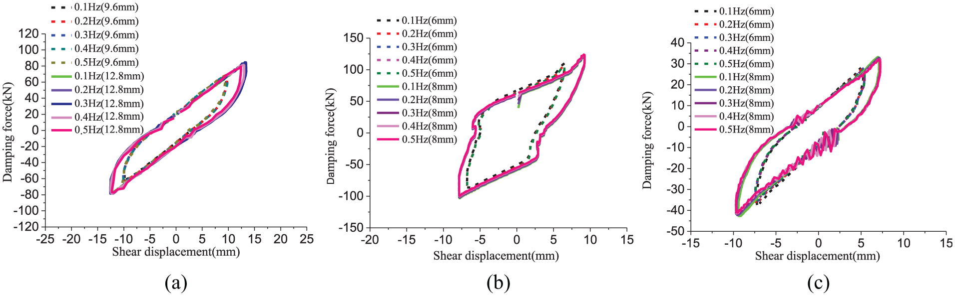
Hysteresis curves of the viscoelastic dampers with different loading frequency: (a) Damper S-A, (b) damper S-B and (c) damper S-C.
Effect of strain amplitude on the mechanical properties of high damping viscoelastic dampers
Figure 11 shows hysteresis curves of the dampers at different strain amplitude. It can be seen that the slope and the enveloping area of hysteresis curves of the dampers increase obviously with the increase of strain amplitude. In addition, the hysteresis curves of dampers are ellipse-shaped when the shear strain is not greater than 60%, which exhibits the typical energy dissipation characteristics of viscoelastic damper. However, as the shear strain is greater than 60%, the viscoelastic material starts to harden, the pinching effect is obvious in the central parts of the hysteresis curves, and the curves are inverse S-shaped. In short, the hysteretic behavior of viscoelastic damper is significantly affected by the strain amplitude.

Hysteresis curves of the viscoelastic dampers at different strain amplitude: (a) Damper S-A (0.1 Hz), (b) damper S-B (0.1 Hz) and (c) damper S-C (0.1 Hz).
Fatigue performance of viscoelastic dampers
According to Chinese design code, the anti-fatigue performance of the damper should be checked. The basic requirement is that the major mechanical indexes of viscoelastic damper should not decrease by more than 15% after 30-cycle loading with the design displacement amplitude. For the low-cycle fatigue property tests, 30 cycles loading were conducted under 0.1 Hz loading frequency for the amplitude of 10 mm and 16 mm, respectively. To evaluate low-cycle fatigue properties of the dampers at 100% shear strain, the test results at the third cycle are compared with those at the 30th cycle. The main evaluation indexes include the maximum damping force, the loss shear modulus and the loss factor. The calculated results are shown in Table 6.
Fatigue indexes comparison of viscoelastic dampers.
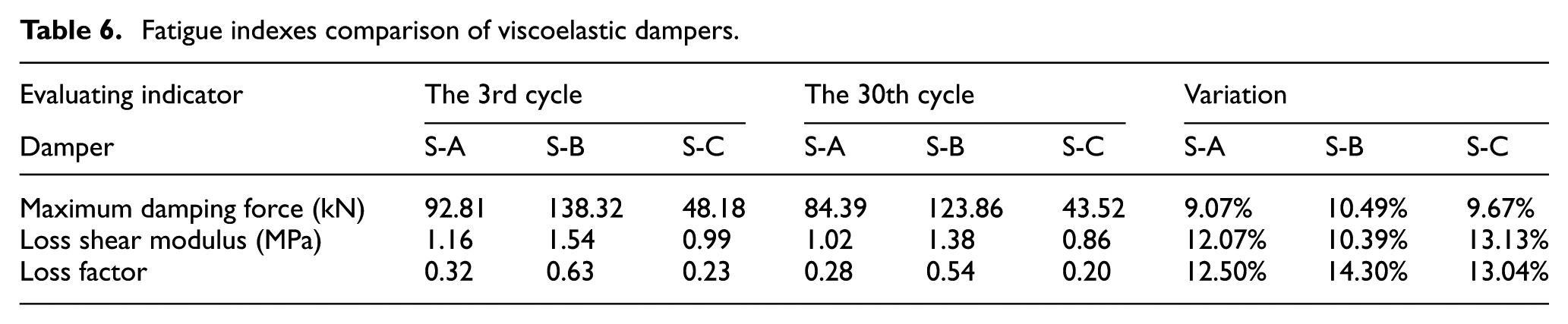
According to the above comparison, the maximum damping force, loss shear modulus and loss factor of the three dampers decreased after 30 cycles cyclic loading, and the maximum reduction percentages are 10.49%, 13.13% and 14.30%, respectively, which shows the slight degeneration of low cycle fatigue properties of the dampers. Figure 12 shows hysteresis curves of the dampers showing the fatigue performance. It can be seen that the strength degradation is slight and the dampers possess good fatigue resistance.

Hysteresis curves of dampers showing fatigue performance.
Restoring force model of viscoelastic dampers
The model of equivalent stiffness and damping
In this model, two important parameters, equivalent stiffness and equivalent damping, are used to analyze the mechanical properties of viscoelastic dampers. Viscoelastic damper is regarded as a type of velocity-depending damper. The force–displacement relationship of the model subjected to harmonic excitation at a given circular frequency can be expressed as

Where


where
The slopes and the fullness degree of the model curves are controlled by the storage energy stiffness and the loss factor, respectively. The mathematical model of equivalent stiffness and damping can be expressed as

Where

Comparison between experimental curves and the model curves of viscoelastic dampers: (a) Damper S-A, (b) damper S-B and (c) damper S-C.
Comparison between model results and experimental results.
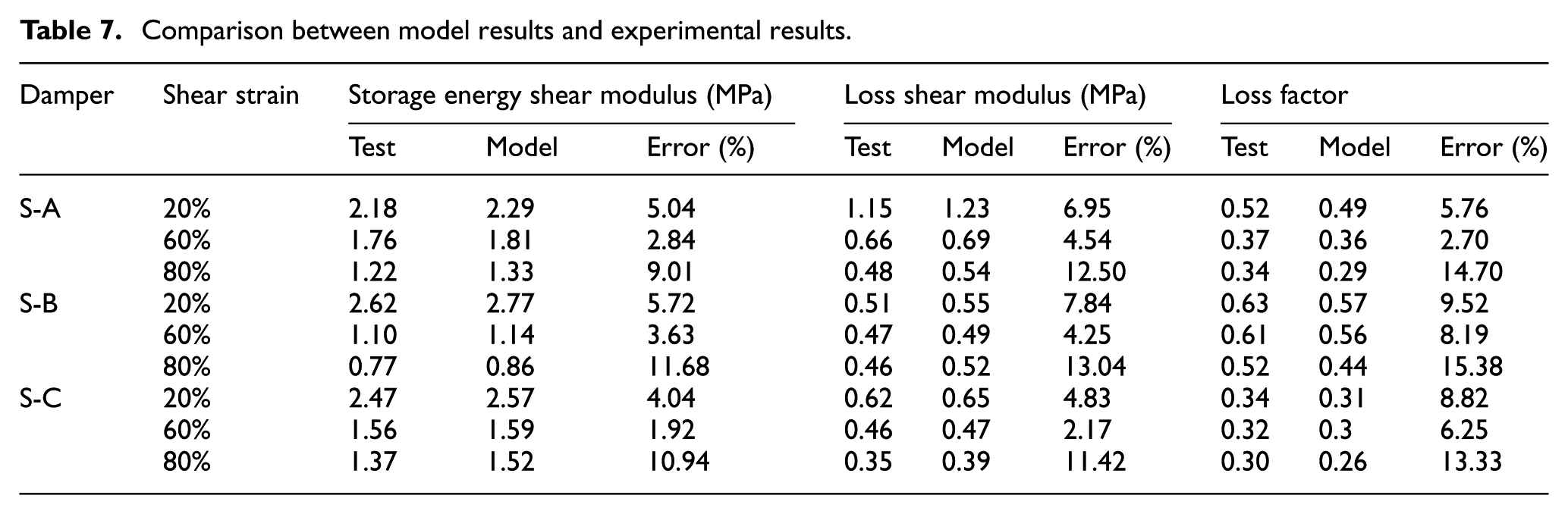
When the shear strain is not greater than 60%, the model curves agree well with the experimental curves. As the shear strain is greater than 60%, the pinching effect becomes significant due to the hardening of viscoelastic materials, and the experimental curves are inverse S-shaped. The maximum error of the mechanical indexes is 15.38% as the shear strain is up to 80% according to Table 7. The model curves cannot capture the nonlinear mechanical performance of the dampers at large shear strain, and the accuracy of the model decreases. The application of this model in the condition of large shear strain needs further investigation.
The Bouc–Wen model
The Bouc–Wen model was introduced by Bouc in 1967 and later extended by Wen in 1976. Since then, the Bouc–Wen model has been successfully applied in engineering practice in order to capture the dynamic behavior of structures with various nonlinear dampers (Bouc, 1967; Karavasilis et al., 2012; Zhou et al., 2013; Zhu et al., 2011).
The Bouc–Wen model can be expressed as


where
According to the previous research (Zhou et al., 2013; Zhu et al., 2011), the parameter A and n can be taken as 1 for viscoelastic damper, then equation (15) can be expressed as

On the basis of the range of positive and negative values of




In the light of analytical solutions of the above differential equation, equation (14) can be derived as

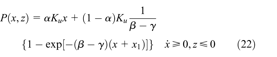
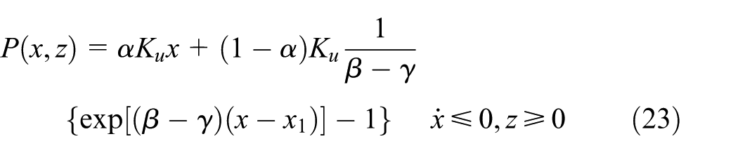

where
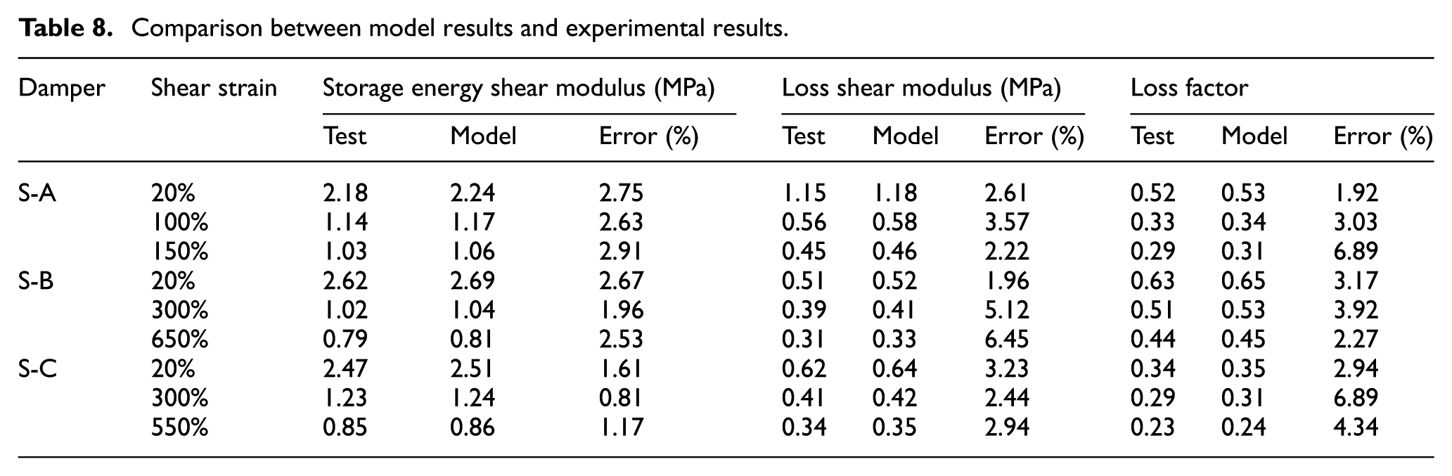
The comparison of the mechanical indexes is shown in Table 8. The maximum error is not greater than 7%, which indicates that the Bouc–Wen model can capture the nonlinear mechanical performance of the dampers at different strain amplitudes. The comparison between the model curves and experimental curves is shown in Figure 14. It can be seen that the Bouc–Wen model can simulate the hysteretic behaviors of the viscoelastic dampers well and reflect the hardening characteristic of the rubber material for a wide range of strain amplitudes.
Comparison between model results and experimental results.
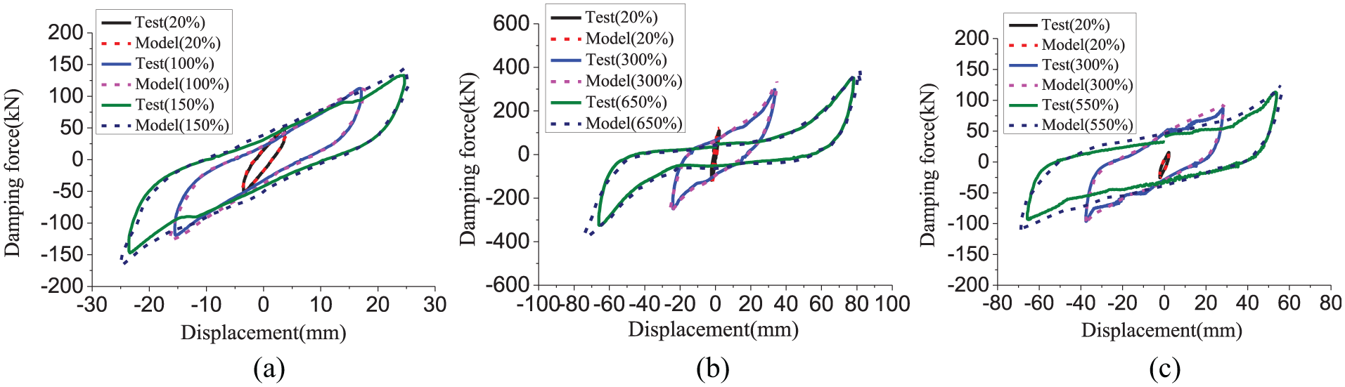
Comparison between experimental curves and the model curves of viscoelastic dampers: (a) Damper S-A, (b) damper S-B and (c) damper S-C.
Conclusions
Experimental studies and numerical analysis of the high damping viscoelastic dampers were carried out. The numerical models developed by previous researchers are adopted to simulate the hysteretic behaviors of the high damping viscoelastic dampers. The suitability of models is verified by the experimental results. The following conclusions can be derived from the above research:
The Mooney–Rivlin model, the Yeoh model and the Prony series are applicable to simulate the constitutive model of high damping rubber within their applicable strain range.
The high damping viscoelastic dampers possess excellent energy dissipation capacity.
As the loading frequency ranges from 0.1 Hz to 0.5 Hz, the mechanical properties of the high damping viscoelastic dampers change slightly. It confirms that the hysteretic behaviors of the dampers are less affected by the loading frequency.
The hysteretic behaviors of the viscoelastic dampers are affected significantly by the strain amplitude.
The maximum shear strain of viscoelastic dampers S-B and S-C could be up to 600% and 500%, respectively, which indicates that the dampers possess high deformation capacity.
The variation of the mechanical parameters of the three dampers is not greater than 15% after 30 cycles loading, which demonstrates that the dampers have excellent fatigue resistance and stable mechanical performance.
The Bouc–Wen model is applicable to simulate the mechanical performance of the high damping viscoelastic damper under a wide range of shear strain. The model of equivalent stiffness and damping has the advantage of clear concept and simple calculation. However, it can only reflect the mechanical properties of the damper with low shear strain not greater than 60%.
Footnotes
Declaration of Conflicting Interests
The author(s) declared no potential conflicts of interest with respect to the research, authorship, and/or publication of this article.
Funding
The author(s) disclosed receipt of the following financial support for the research, authorship, and/or publication of this article: The financial support provided by National Key Research and Development Program of China under Grant No. 2017YFC1500701, the National Natural Science Foundation of China under Grant No. 51408170, the Academic Innovation Plan of Hainan Science and Technology Association for Young Scientists under Grant No. 201601, Hainan Key R&D Program under Grant No. ZDYF2016151, and the Midwest Key Areas Construction Project Plan of Hainan University under Grant No. ZXBJH-XK011 is gratefully appreciated.
