




Abstract
In this article, the flexural durability of three types of seawater sea-sand concrete beams that were fully reinforced with steel bars, 304 stainless steel bars, or fiber-reinforced polymer bars were comparatively tested. Beam specimens were conditioned in a 40°C seawater wet–dry cycling environment and a 50°C seawater immersion environment for up to 9 months with an interval of 3 months. The test results showed that in the absence of an additional current (even if the temperature is elevated), the flexural properties of the seawater sea-sand concrete beams reinforced with steel bars and stainless steel bars after 9 months of conditioning did not show any degradation trends. However, for the carbon fiber–reinforced polymer bar–reinforced beams (top bars and stirrups are both basalt fiber–reinforced polymer bars) conditioned in the high-temperature and high-humidity environment considered, the failure modes changed from concrete crushing in the pure bending section to concrete crushing at loading points in the shear span with a maximum reduction of 30% in the ultimate load-carrying capacity. In addition, the crack distribution of conditioned carbon fiber–reinforced polymer bar–reinforced beams became sparse, and the crack width increased significantly, with a maximum of 2.2 times. In addition, obvious sudden load drops were observed in the tested load–displacement curves.
Keywords
Introduction
As the scale of infrastructure construction increases year by year, the demand for concrete, which is the mainstay of infrastructure materials, is increasing. However, excessive excavation of river sand, which is an important component of concrete, will affect the navigational safety of ships in river channels, damage the ecological environment, and even cause geological disasters such as floods and landslides (Aswath, 2013; Economist, 2009). Therefore, many countries and regions have classified river sands as mineral resources and even enforce criminal penalties for illegal mining (Li, 1988). In this context, the supply of river sand is not keeping up with the demand. Moreover, with the rapid compression of human living space, coastal development becomes inevitable in the future. Increasingly more infrastructure will be built in coastal areas (Maddocks, 2009), which requires the transportation of large amounts of river sand and freshwater resources from inland areas. In coastal areas, there is a large amount of seawater and sea-sand resources that can be locally sourced. Rationally utilizing these resources in the preparation of concrete will provide great economic benefits.
However, the first thing that needs to be addressed when seawater and sea sand are directly used to cast concrete is the corrosion of internal steel bars. Direct use of carbon steel reinforcements in seawater sea-sand concrete (SWSSC) is almost impossible. Therefore, finding suitable alternative reinforcement is the prerequisite for the practical application of SWSSC. Stainless steel bars, which have far better corrosion resistance properties than ordinary carbon steel bars, are one of the alternative solutions. However, because of their high price, they are currently only used in a small number of major projects in severe service environments. Moreover, research also showed that traditional 304 stainless steel will still rust under long-term erosion of chloride ions (Feng et al., 2016; Tian et al., 2014). Unlike metallic materials, which are afraid of the electrochemical corrosion caused by chloride ion-induced passivation film destruction, non-metallic materials, for example, fiber-reinforced polymer (FRP) composites, are not obviously adversely affected by chloride ions (Robert and Benmokrane, 2013). Many scholars believe that FRP is an ideal reinforcing material for the SWSSC environment (Chen et al., 2017; El-Hassan et al., 2017; Li et al., 2016a, 2016b, 2018; Teng et al., 2011; Wang et al., 2017a, 2017b; Xiao et al., 2017). However, numerous accelerated aging tests have shown that the mechanical properties of FRP will still tend to decrease in the concrete alkaline environment (Benmokrane et al., 2002, 2015; Ceroni et al., 2006; Chen et al., 2006). This is mainly due to the fiber/resin interface debonding caused by the diffusion of OH−/H2O contained in the concrete pore solution into the resin matrix. Studies have shown that the environmental humidity and temperature have a significant impact on the degradation rate of the mechanical properties of FRP (Dong et al., 2017b; Huang and Aboutaha, 2010; Robert et al., 2010). When FRP bars are used as internal reinforcements in the SWSSC environment, they will also face the above problem, and the interaction may be even more complex (the micro-pore solution contains chloride ions).
At present, numerous accelerated tests have been carried out on the long-term behavior of FRP bars in the marine environment (Al-Salloum et al., 2013; Benmokrane et al., 2016; Wang et al., 2017a, 2017b; Zou and Wang, 2018) and on the long-term bond performance of FRP bars with normal concrete or sea-sand concrete (Altalmas et al., 2015; Dong et al., 2016a, 2016b, 2016c, 2017a; El Refai et al., 2014a, 2014b; Yan and Lin, 2017). However, there is still a lack of research on the degradation of the long-term performance of concrete beams reinforced with FRP bars. Moreover, for the SWSSC beam, there is a concern not only for the corrosion of the straight bars but also for the corrosion of the bent stirrups in terms of shearing and torsion resistance. At present, studies on the durability of SWSSC beams fully reinforced with FRP bars are very few.
For this reason, this article compared the durability of three types of SWSSC beams that were fully reinforced with ordinary steel bars, stainless steel bars, or FRP bars. Beam specimens were conditioned in two types of simulated ocean environments (i.e. wet–dry cycling and immersion). The ocean environment with high temperature and high humidity was specially designed to accelerate the degradation rate of FRPs. As for the two types of metal bar–reinforced SWSSC beams, although the accelerated corrosion mechanism is different, they were placed in the same environment to keep the environment consistent. This study is of great significance for fully understanding the durability of the new FRP bar–reinforced SWSSC structure in the ocean environment.
Experimental test
Materials
Reinforcing bars
As shown in Figure 1, three types of tensile bars, that is, the steel bar (type HRB 400 grade in the Chinese specification), the stainless steel bar (type 304), and the carbon fiber–reinforced polymer (CFRP) bar, were used in this study. The nominal diameters of the steel bar, the stainless steel bar, and the CFRP bar were 12.0, 12.0, and 8.0 mm, respectively. The commercially available CFRP bars were provided by Jiangsu Hengshen Co., Ltd., China. The tested tensile properties are shown in Table 1. Note that nominal diameters were used for the calculation of tensile properties in this article.

Reinforcing bars: (a) tensile bars and (b) BFRP stirrups.
Properties of tensile bars.
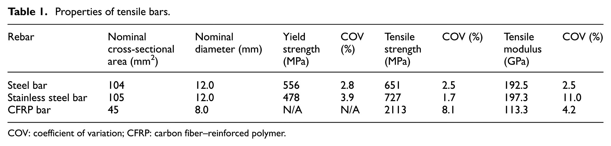
COV: coefficient of variation; CFRP: carbon fiber–reinforced polymer.
For the traditional carbon steel bar–reinforced beam, the top bars and the stirrups were both plain steel bars with a nominal diameter of 6 mm (type HPB 235 grade in the Chinese specification). For the stainless steel bar–reinforced beam, the top bars and the stirrups were both plain stainless steel bars with a nominal diameter of 6 mm (type 304). For the non-metal bar–reinforced beam, the top bar was the basalt fiber–reinforced polymer (BFRP) bar with a nominal diameter of 10 mm, and the stirrups (as shown in Figure 1(b)) were BFRP bars with a nominal diameter of 8 mm. According to ASTM D7205-11 (2011), the measured tensile strength of the 10 mm BFRP bar was 1141 MPa, and the modulus of elasticity was 47.6 GPa. The 8 mm BFRP stirrup was produced in the same batch and was bent before the resin cured. The basalt fibers were all provided by Zhejiang GBF Basalt Fiber Co., Ltd., Hengdian, China. The resin matrix was the vinyl ester provided by Reichhold Company, United States.
SWSSC
The sea sand used in this article was purchased from Zhangzhou, Fujian Province, China (a city close to the Taiwan Strait) and was the same batch as that used in Dong et al. (2018). As shown in Table 2, referring to the Chinese specification JTG E42-2005 (2005), the calculated fineness modulus after the sieving test was 2.404, which belongs to the class of medium sand. In addition, X-ray fluorescence spectrometry (XRF) was used to analyze the chemical composition of the used sea sand. The results are also shown in Table 2. It can be seen that the content of chloride ions was approximately 0.08%. Natural seawater taken from the outskirts of the Lianyungang harbor was used as mixing water (the concentration of chloride ions was approximately 1.9%).
Sieving and chemical analysis results of the adopted sea sand.

The Portland cement used in this article was type P·O 42.5 in Chinese standard, and the coarse aggregates were ordinary gravels having a continuous particle size of 5–20 mm. The adopted mixing ratio of seawater:cement:sea sand:coarse aggregate was 0.45:1.00:1.50:2.50. It is worth noting that after the contained chloride ions in seawater added, the actual chloride ion ratio in the sea sand was equivalently updated to be 0.65%, which exceeded the allowed values in specifications (ACI Committee 222, 2001; JASS 5, 1993; JGJ 52-2006, 2006) by approximately 10 times. The concrete strength (fcu) was tested using a 150 mm cube, and the 28-day value was 50.5 MPa.
Simulated ocean environments
As shown in Figure 2, to simulate the natural ocean environment, a large-scale ocean environment simulation tank was built in the laboratory. Both the immersion environment in the underwater zone and the wet–dry cycling environment in the tidal zone can be simulated by this device. Moreover, to accelerate the aging process, an electric heating system was coupled to elevate the temperature of the seawater. The control precision of temperature was ±3°C, and the seawater temperature could be tested regularly. The tank was covered with galvanized steel covers during operation to prevent excessive evaporation loss of the water. Meanwhile, an automatic water supply device was equipped to keep the water level constant. The artificial seawater used was a NaCl solution with a mass fraction of 5%. One wet–dry cycle involves 6 h of drying and 6 h of immersion. The temperature during the 6 h of immersion was 40°C, and a high-pressure blower with a maximum flow rate of 1.5 m3/min (Shenzhen Ruifeng Vacuum Mechanical and Electrical Equipment Co., Ltd.) was used to accelerate the drying of specimens during the 6 h of drying. The temperature of the continuous immersion environment was 50°C. The selected accelerated test environment is similar to those adopted by other scholars (Robert and Benmokrane, 2013; Tian et al., 2014) in the existing literature, which are considered reasonable in terms of percentage of NaCl and the maximum temperature.
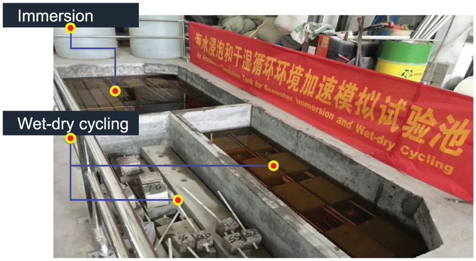
Specimens conditioned in the simulated ocean environments.
Specimen design
As shown in Figure 3(a), three types of reinforcement cages were designed and manufactured. They were the steel bar cage, stainless steel bar cage, and CFRP bar cage. The stirrup spacings in the pure bending section and the shear span were 150 and 40 mm, respectively. As shown in Figure 3(b), the reinforcement cages were placed in the formwork, and the SWSSC was prepared on-site at the laboratory. As shown in Figure 3(c), the casted SWSSC beams were cured in laboratory air conditions. The concrete cover of all beams in this article was 20 mm. As shown in Table 3, the relationship between the tensile reinforcement ratio (ρf) and the reinforcement ratio producing the balanced strain condition (ρfb) was determined to show the reinforcing status of the three types of beams. It should be noted that this article focused on evaluating the durability of beam specimens themselves. Therefore, there is no special emphasis on the need for the same reinforcement ratio at the beam design.
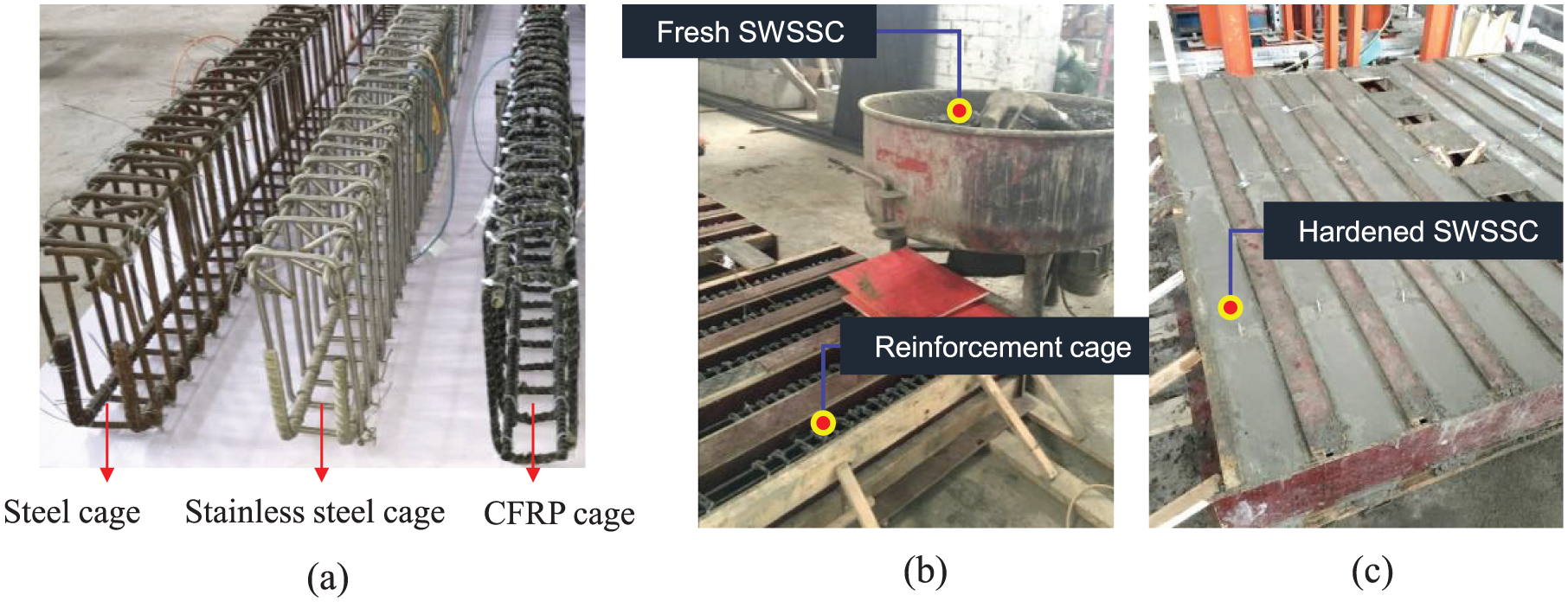
The fabrication of beam specimens: (a) three types of reinforcement cages; (b) concrete pouring; (c) concrete curing.
Test program.

CFRP: carbon fiber–reinforced polymer.
ρf is the tensile reinforcement ratio, and ρfb is the reinforcement ratio producing balanced strain conditions; “–” means no specimens prepared.
The accelerated aging program is also shown in Table 3. After 28 days of curing, all beams except for the control beams were placed into the above-mentioned ocean environment simulation tank to undergo environmental aging. When beam specimens reached a specified duration of aging, they were taken out of the tank and dried in air for 2 days before the flexural performance tests were performed. Considering the fact that the strength of SWSSC might improve in the high-temperature seawater environment due to the further hydrated reaction, 150 mm cubes were placed in the same conditions to monitor the change of concrete strength. The measured results showed that the strength of SWSSC increased from 50.5 MPa for the control group to approximately 63.6 MPa for the environmentally conditioned groups.
Test setup
As shown in Figure 4, the SWSSC beams, which have a length of 2.4 m, were all tested with four-point bending over a simply supported clear span of 2.1 m and a 0.75 m shear span. A steel spreader beam was used to transfer the load from the loading head. The load was applied in a displacement-control mode. Before beam cracking, the load was applied at a rate of 0.3 mm/min. For metal bar–reinforced beams, which have a yielding stage, the loading rate was 0.75 mm/min before yielding and was 1.0 mm/min until failure. For CFRP bar–reinforced beams, the loading rate was changed to 1.0 mm/min once concrete cracking occurred until failure. Three linear variable differential transducers (LVDTs) were installed under the beams at midspan and loading points, and two LVDTs were installed on the beam supports to offset its settlement. All measurements, including load and displacement, were recorded by a TDS-530 data acquisition system. The appearance and development of cracks were observed by visual inspection, and their widths at the level of the longitudinal reinforcement were kept monitored at the same location with a digital crack width viewer at an interval of every 5 kN.

Beam dimensions and reinforcement details: (a) elevation and (b) cross sections (unit: mm).
Test results
Change of the failure mode
The failure modes of the tested beams are shown in Figures 5 and 6. The environmentally conditioned beams are labeled with three characters in the format of A-B-C. The first character “A” represents the type of reinforcement, where “Steel” means that the reinforcements are carbon steel bars, “SS” means that the reinforcements are stainless steel bars, and “CFRP” means that the reinforcements are CFRP bars (the top bars and stirrups are BFRP bars). The second character “B” represents the type of accelerated environment experienced, where “I” denotes the immersion environment, and “WD” denotes the wet–dry cycling environment. The last character “C” represents the duration of aging, where “3,”“6,” and “9” represent aging of 3 months, 6 months, and 9 months, respectively. In addition, “control” represents reference beams that did not experience environmental effects.

Failure modes of SWSSC beams reinforced with metal reinforcements.

Failure modes of SWSSC beams reinforced with non-metal reinforcements.
As shown in Figure 5, the failure modes of steel bar–reinforced beams and stainless steel bar–reinforced beams were not changed after being environmentally conditioned, and they were all concrete crushing after steel/stainless steel yielding in the middle pure bending section. As shown in Figure 6, the failure modes of CFRP bar–reinforced beams with 3 months of aging were consistent with that of the reference beam, and they were concrete crushing in the middle pure bending section. However, when the aging was extended to 6 months and 9 months (i.e. CFRP-I-6, CFRP-I-9, CFRP-WD-6, and CFRP-WD-9 specimens), their failure modes changed to be concrete crushing close to the loading point in the shear span. The mechanism of the above-mentioned phenomenon will be explained in detail below.
Load–displacement curves and characteristic loads
The measured load–midspan displacement curves for all tested beams are shown in Figure 7. It should be noted that in order to avoid indistinguishability due to overlapping curves, the curves of the environmentally conditioned beams were shifted along the abscissa in sequence. The characteristic loads and characteristic displacements of each curve were determined, and the results are listed in Table 4. The following information can be drawn from Figure 7 and Table 4:
As shown in Figure 7(a), for the steel bar–reinforced beams, due to the further improvement of concrete strength, the cracking loads improved by 33%–60%, and the improvements were relatively random. It should be noted that due to an error in the test operation, the ultimate displacement of the steel-control beam was not effectively measured (a “*” superscript was added to the data, as shown in Table 4), but the values of characteristic loads were not affected. It can be concluded from the curves in Figure 7(a) and the values in Table 4 that, generally, the steel bar–reinforced beams were not significantly affected by the adopted environment in this article, and the small amounts of increase (maximum increase of 7% for the yield load and 11% for the ultimate load) were mainly due to the increase in the strength of the concrete.
As shown in Figure 7(b), for the stainless steel bar–reinforced beams, after 9 months of aging, the cracking loads increased by 30%–50%, the yield loads increased by 9%–12%, and the ultimate loads increased by 10%–13%. The displacement ductility coefficient (Δu/Δ y ) of the SS-I-9 slightly reduced by 22%, while it was almost unchanged for the SS-WD-9 specimen. Overall, in the test period of this article, the ocean environment was seen to have no obvious macro effect on the performance of stainless steel bar–reinforced beams.
As shown in Figure 7(c), for the CFRP bar–reinforced beams, after experiencing the specially designed accelerated environment for FRP materials with a high temperature in this article, the load–displacement curves, the characteristic loads, and displacements all showed obvious changes. This issue is where the analysis and explanation need to be focused on in this article. First, it can be seen from the load–displacement curves that the sudden load drops due to cracking became increasingly obvious. It is believed that this phenomenon is mainly due to the weakened interfacial bond properties between the tensile CFRP bars and SWSSC after being conditioned in the high-temperature and high-humidity environment. Moreover, due to a more severe bond degradation, the amplitude of the load drop in the 50°C immersion environment (e.g. CFRP-I-9) was more pronounced than that in the 40°C wet–dry cycling environment (e.g. CFRP-WD-9). As for the characteristic loads, first, the cracking loads increased, with a maximum of 60%, due to the increase in concrete strength. The change in ultimate loads was not obvious when the failure modes were still concrete crushing after 3 months of aging, for example, the ultimate load of CFRP-I-3 slightly decreased by 9%, while the value of CFRP-WD-3 slightly increased by 5%. However, as the duration of aging increased, the failure mode of the CFRP-beams transformed from concrete crushing in the middle pure bending section to concrete crushing in the shear-bending coupled section, and the ultimate loads reduced significantly. For example, the ultimate load of the CFRP-I-9 specimen reduced by 30%. Due to the change in the failure mode, the ultimate midspan displacement also decreased accordingly. See Table 4 for detailed values. The possible reason for the change in the failure mode will be discussed in the following section in combination with the accelerated degradation mechanism of FRP materials in high-temperature and high-humidity environments.
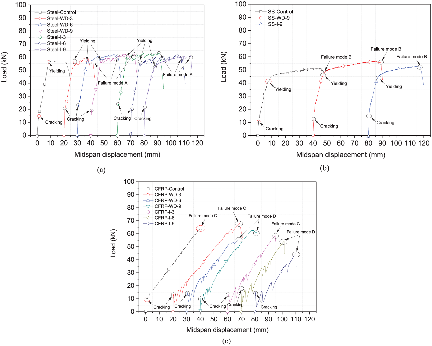
The load versus midspan displacement curves: (a) steel bar–reinforced SWSSC beams, (b) stainless steel bar–reinforced SWSSC beams, and (c) CFRP bar–reinforced SWSSC beams.
Beam test results.
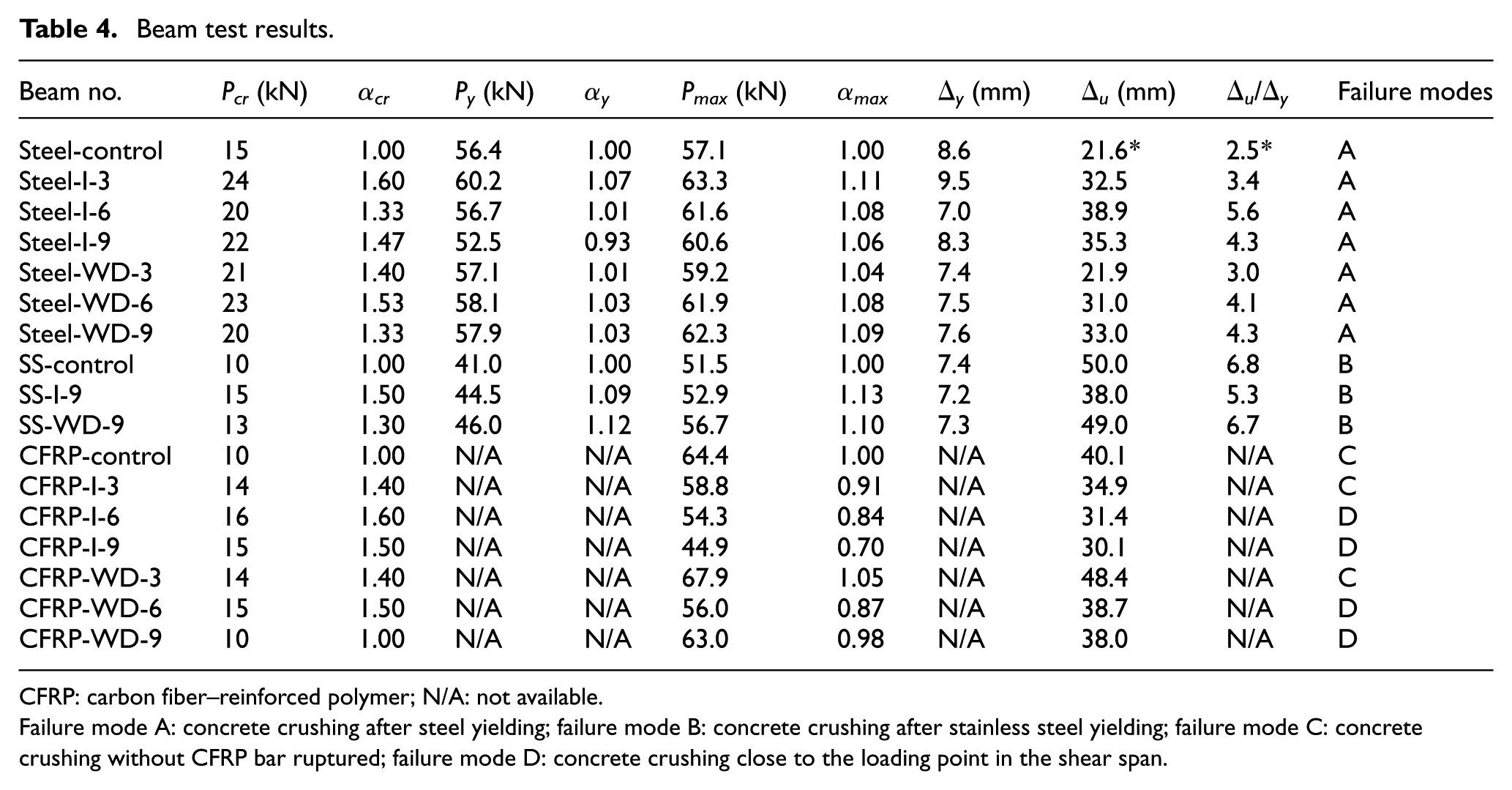
CFRP: carbon fiber–reinforced polymer; N/A: not available.
Failure mode A: concrete crushing after steel yielding; failure mode B: concrete crushing after stainless steel yielding; failure mode C: concrete crushing without CFRP bar ruptured; failure mode D: concrete crushing close to the loading point in the shear span.
Crack distributions
The crack distributions of all tested beams after bending tests are shown in Figure 8. As shown in Figure 8(a), for the steel bar–reinforced beams, the failure modes before and after aging were all flexural failure with concrete crushing in the middle pure bending section. There were no obvious changes for the crack distributions except for a slightly decreasing trend for the shear cracks after environmental conditioning. The same results were observed for the stainless steel bar–reinforced beams, as shown in Figure 8(b). Basically, no changes were observed for the crack distributions before and after conditioning. The crack distributions of CFRP bar–reinforced beams are shown in Figure 8(c); after environmental conditioning, the cracks became obviously sparse. Moreover, the cracks became sparser as the duration of aging increased. For example, there were three main cracks in the pure bending section of beam CFRP-I-3, but only one main crack for beam CFRP-I-9. In addition, the change in failure mode is also clearly illustrated in Figure 8(c).

Crack distributions of all tested beams: (a) steel bar–reinforced beam, (b) stainless steel bar–reinforced beam, and (c) CFRP bar–reinforced beam.
Change of the maximum crack width
The tested maximum crack widths in the pure bending section of the three types of SWSSC beams are shown in Figure 9. Taking into account the discreteness of the cracks, only the data from the control group and the longest aged group (i.e. 9 months) are compared. As shown in Figure 9(a), the cracks of environmentally conditioned steel bar–reinforced beams were slightly wider than those of the control beam (except for Steel-WD-9 at 30 kN). In addition, the beams conditioned in the continuous immersion environment (Steel-I-9) had wider crack widths than the ones exposed to the wet–dry cycling environment (Steel-WD-9). For example, the maximum crack widths of the steel-control, Steel-WD-9, and Steel-I-9 at 45 kN were 0.184, 0.207, and 0.253 mm, respectively. However, as shown in Figure 9(b), for the stainless steel bar–reinforced beams, the crack widths of the environmentally conditioned beams were lower than that of the control beam. Moreover, there was little difference in the widths of cracks between the two environments adopted in this article. Overall, for metal-bar-reinforced beams, considering the discrete nature of concrete cracks and the tested indistinguishable crack width differences, it can be considered that the crack width was basically unchanged. As shown in Figure 9(c), for the CFRP bar–reinforced beams, the maximum crack width increased obviously after conditioning in the high-temperature seawater environment. A preliminary bond durability test with only one sample for each group was conducted simultaneously. The ultimate bond strength of unconditioned control specimen was 30.5 MPa, while after 6 months of wet–dry cycling and 6 months of immersion, the bond strength reduced to be 14.8 and 11.7 MPa, respectively (Lian, 2017). Thus, the degraded bond strength between CFRP bars and SWSSC was believed to be the main reason for the sparse crack distribution (as shown in Figure 8(c)). For example, under the 45 kN load level, the maximum crack widths of CFRP-control, CFRP-WD-9, and CFRP-I-9 were 1.104, 2.116, and 2.438 mm, respectively.

The load versus maximum crack width curves: (a) steel bar–reinforced beam, (b) stainless steel bar–reinforced beam, and (c) CFRP bar–reinforced beam.
Discussion
Mechanism of the failure mode change
As described above, the failure mode of the CFRP bar–reinforced beams (with BFRP as stirrups) changed from concrete crushing in the middle pure bending section to concrete crushing in the shear span close to the loading point after 6 and 9 months of conditioning in the high-temperature seawater in this article. As shown in Figure 10, the CFRP-control and the CFRP-I-6 specimen are selected as representatives to explain the reason for this change. As shown in Figure 10(a), for the control beam, due to a good bond performance between the BFRP stirrups and concrete at the shear span, the cracks developed relatively well, making the BFRP stirrups to be involved in providing shear resistance. Referring to ACI 440.1R-15 (2015), the total shear resistance can be calculated with the following equations



where V is the total shear resistance, Vc is the shear resistance nominal provided by the concrete, Vf is the shear resistance nominal provided by the stirrups,

Mechanism of the failure mode change: (a) CFRP-control and (b) CFRP-I-6.
The calculated Vc is 9.52 kN, and the Vf is 103.31 kN (the strain of BFRP stirrups is taken as 0.004 in the calculation). Therefore, the control beam has a shear capacity of 2(Vc + Vf), which is 225.66 kN. This value is much higher than the tested flexural resistant capacity, which is 64.4 kN. Thus, the control beam failed in the concrete crushing mode. However, as shown in Figure 10(b), the cracks at the shear span of the environmentally conditioned beam became very sparse, and no diagonal shear cracks were observed. The only crack developed in the shear span became vertical along with the stirrups. The authors’ previous research on the bond durability between BFRP bars and SWSSC showed that after 9 months of aging, the bond stress retention was 92% in the wet–dry cycling environment and 78% in the immersion environment (Dong et al., 2018). Therefore, the authors inferred that the above phenomenon is mainly due to the degradation of the bond property of the BFRP stirrup and concrete after accelerated environmental aging. As is known, when the cracks do not pass through the stirrups, the contribution of the stirrups to the shear capacity is greatly reduced, and eventually, the shear-resistant capacity of the environmentally conditioned beam was lower than its flexural resistant capacity. The beam failed in flexure due to local defects induced by shear loads at the loading point in the shear span.
Different degradation mechanisms for metal bars and non-metal bars in SWSSC
First, in practical engineering, even if the reinforcements are stainless steel bars (type 304), it is explicitly forbidden to use seawater and natural sea sand, which contains excessive chloride ions, to cast concrete directly. This is because the excessive internally contained chloride ions will accelerate the destruction of the passivation film on the surface of the steel bar. Once the passivation film is damaged, a micro-battery will form on the surface of the steel bar. The steel bar will enter a rapid corrosion period. Furthermore, the corrosion product will expand in volume and cause concrete cracking. The cracks will further accelerate the corrosion of the steel bar. However, for the environments and duration of aging adopted in this article (the longest being 9 months of immersion or wet–dry cycling), the passivation film may have only suffered minor damages or was still in the process of being damaged, as the corrosion of the reinforcing steel was not obvious. This could explain the basically unchanged mechanical performance of the steel bar–reinforced beams. Thus, in follow-up experiments, accelerated electrochemical corrosion experiments with an additional current should be used so that a longer equivalent effective service life can be modeled.
Studies on the durability of FRP bars have noted that the internal alkaline environment of concrete could reduce the mechanical properties of the FRP bars themselves (Benmokrane et al., 2002; Ceroni et al., 2006; Nkurunziza et al., 2005), as well as the bond properties (Dong et al., 2016b; El Refai et al., 2014a, 2014b). Moreover, the degradation rate will be significantly accelerated under elevated temperatures. This is because, at a higher temperature, the diffusion rate of ions and molecules is significantly accelerated. At present, the Arrhenius model is commonly used to characterize the effect of temperature on the degradation rate of FRPs. However, due to the variety of types of FRP bars and their relatively short application time in actual engineering, the correspondence between the actual service environment and the elevated temperature environment is still at the theoretical research level. Generally, the following formula is used to calculate the acceleration effect caused by temperature

where TSF is the time shift factor between two temperatures, T0 is the low temperature, and T1 is the high temperature. Ea/R is a constant determined by test data. Based on the above formula, Dejke and Tepfers (2001) had noted that 18 months in concrete at 60°C correspond to 100 years in outdoor conditions in the Southwest of Sweden (where the mean annual temperature was 7°C) for the glass fiber–reinforced polymer (GFRP) reinforcement bars used in their paper. According to the prediction method adopted by Dejke and Tepfers (2001), the 9 months in a 50°C immersion environment in this article can be approximately equivalent to 25.6 years in the actual outdoor environment (the average temperature is also set at 7°C). From past research by the authors (Wang et al., 2017b), the existing prediction model is very conservative. More research is needed to develop accurate prediction model to convert accelerated corrosion results to long-term performance in real-life environment. In addition, the high-temperature and the high-humidity environment will also reduce the interfacial bonding properties between FRP bars and concrete, which will greatly reduce their composite behavior, resulting in sparse and wider cracks. Readers should fully understand the different degradation mechanisms of metal bars and FRP bars in the environments adopted in this article and should not have the impression that FRP is significantly inferior to metallic materials.
Conclusion
Based on the test results and analysis of this article, the following main conclusions are drawn:
Due to the strength improvement of the SWSSC in high-temperature seawater, the cracking loads of the environmentally conditioned beams have been increased to varying degrees, with the maximum increase observed being 60%.
For the carbon steel bar–reinforced SWSSC beams, although this combination is not allowed in practice, the passivation film at the steel bar surface may have only suffered minor damages or was still in the process of being damaged under the aging conditions (longest 9 months) and environments (elevated temperature instead of electrification) considered in this article. This is the reason why the mechanical properties of the steel bar–reinforced beams did not appear to be degraded. Similarly, for the stainless steel bar–reinforced SWSSC beams, the mechanical properties were not significantly degraded under the conditions considered in this article.
For the FRP bar–reinforced SWSSC beams conditioned in the immersion and wet–dry cycling environments for 6 and 9 months, the failure mode changed from concrete crushing in the middle pure bending section to concrete crushing in the shear span due to a reduced bond strength between BFRP stirrups and the SWSSC, which resulted in a reduction of the load-carrying capacity by up to 30%.
For the FRP bar–reinforced SWSSC beams, the sudden load drop due to cracking during testing became apparent for the environmentally conditioned beams, the crack distribution became sparse, and the crack width increased significantly, with a maximum of 2.2 times.
Footnotes
Declaration of Conflicting Interests
The author(s) declared the following potential conflicts of interest with respect to the research, authorship, and/or publication of this article: We wish to draw the attention of the Editor to the following facts which may be considered as potential conflicts of interest and to significant financial contributions to this work. [OR] We wish to confirm that there are no known conflicts of interest associated with this publication and there has been no significant financial support for this work that could have influenced its outcome. We confirm that the manuscript has been read and approved by all named authors and that there are no other persons who satisfied the criteria for authorship but are not listed. We further confirm that the order of authors listed in the manuscript has been approved by all of us. We confirm that we have given due consideration to the protection of intellectual property associated with this work and that there are no impediments to publication, including the timing of publication, with respect to intellectual property. In so doing, we confirm that we have followed the regulations of our institutions concerning intellectual property. We understand that the corresponding author is the sole contact for the Editorial process (including Editorial Manager and direct communications with the office). He or she is responsible for communicating with the other authors about progress, submissions of revisions, and final approval of proofs. We confirm that we have provided a current, correct email address which is accessible by the corresponding author and which has been configured to accept email from
Funding
The author(s) disclosed receipt of the following financial support for the research, authorship, and/or publication of this article: The authors would like to acknowledge financial support from the National Natural Science Foundation of China (51525801 and 51478106), the National Key Research and Development Program of China (2016YFC0701400), the Australian Research Council (ARC) through an ARC Discovery Grant (DP160100739), the Key Laboratory of Coastal Disasters and Defence of Ministry of Education, Nanjing 210098, and the Fundamental Research Funds for the Central Universities.