
Abstract
The bending behavior of reinforced concrete beams under uniform pressure is critical for the research of the blast-resistance performance of structural components under explosive loads. In this study, a bending test of five reinforced concrete beams with the dimensions of 200 mm (width) × 200 mm (depth) × 2500 mm (length) under uniform load produced by a specific cylinder-shaped rubber bag filled with air or water was conducted to investigate their flexural performances. An air bag load was applied to three of the reinforced concrete beams, a water bag load was applied to one reinforced concrete beam, and the remainder beam was subjected to the 4-point bending load. The experimental results highlighted that the air bag and water bag loading methods can be used to effectively apply uniform loads to reinforced concrete beams. Moreover, the stiffness of the air bag was improved by 123% in accordance with the initial pressure increases from 0.15 to 0.45 MPa. In addition, a finite element model of the test loading system was established using ABAQUS/Standard software. Moreover, the critical factors of the air bag loading method were analyzed using the numerical model. The calculated results were found to be in good agreement with the test data. The established finite element model can therefore be used to accurately simulate the action performances of the uniform loading technique using rubber bags filled with air or water.
Introduction
As is common knowledge, the world is currently in a turbulent state. In particular, there has been a continuous increase in the number of extreme events and threats related to accidental explosions. Significant attention has been directed toward the safety of engineering structures under blast loads. In particular, the mechanical response of reinforced concrete (RC) beams, plates, columns, and other main load-bearing structures subject to blast loads has received considerable research attention (Dennis et al., 2002; Pan et al., 2016; Rao et al., 2018; Rodriguez et al., 2011; Sasani and Sagiroglu, 2008; Shi et al., 2010). Due to the great difficulty and high cost of explosive tests, scholars typically simplify explosive loads into equivalent static loads, and then conduct quasi-static load tests on RC structures or components. The explosive load can be considered as a uniform load when the proportional detonation distance is sufficiently large (Shi et al., 2008; TM5-1300, 1990). Therefore, a method for the accurate simulation of the uniform load in quasi-static tests is required in the field of experimental technology.
At present, the uniform load methods used in structural quasi-static tests can be classified into three categories: (1) the heavy loading method, (2) distribution beam loading method, and (3) air bag loading method. The heavy loading method, as a traditional method, involves the even stacking of the high-mass objects on RC structures, to obtain the uniform load. For example, the soil bags were stacked on the structure, and the total weight due to gravity was considered as the uniform load, as shown in Figure 1 (Gao et al., 2013). However, it is difficult to uniformly and consecutively load and unload structures in this manner. The ultimate load applied on structures using this method is limited due to the maximum stack height. The distribution beam loading method involves the use of a rigid steel beam for the even distribution of the pressure generated by the external load. Yao et al. (2018) conducted a four-point bending test on an RC beam (100 mm × 150 mm × 1400 mm) and established the explicit finite element method (EFEM) using ABAQUS/Explicit software under the same loading conditions. It was demonstrated that the distribution beam loading method can realize real-time loading and unloading; however, slight differences were observed when compared with the ideal uniform load, due to the limited number of nodes. Different from the two abovementioned loading methods, using an air bag as the loading medium can mitigate the drawbacks, which, in recent years, has become a widespread uniform loading method.

Uniformly distributed load produced by the soil bags (Gao et al., 2013).
Chen et al. (2012) conducted several researches on the air bag loading method, which included laboratory tests, theoretical calculations, and finite element (FE) analyses. As observed, the uniform load can be obtained by the air bag loading method, and the feasibility of air bag loading devices was verified by conducting a structural test on the frame section of an aircraft fuselage. To study the post-crack behavior of walls in the second and third stories of unreinforced masonry (URM) buildings, Derakhshan et al. (2013) conducted a unidirectional bending test on a URM wall using an air bag loading system. It was demonstrated that the air bag loading method can produce a significantly superior uniform load, when compared with the conventional methods. Wang et al. (2015) investigated the mechanical properties of non-composite steel–concrete–steel (SCS) sandwich panels under impact-induced impulsive loads in a laboratory, and the uniform dynamic load was realized using an inflated air bag to transfer the impact load from the dropped projectile onto the panels.
Although the air bag loading method has many advantages when compared with the conventional loading methods, its range of applications is limited due to the requirement of a large action area. In particular, the air bag loading method is more suitable for RC plates and not RC beams, given that the length-to-width ratio of RC beams is excessively large. In addition, the error between the air bag loading method and the ideal uniform loading method is uncertain and the critical factors of the air bag loading method require further investigation in future work.
Based on the current research case, a novel uniform loading test method using rubber bags filled with air or water was developed in this study. Four RC beams were tested using this method, and the results were compared with that of the four-point bending method. The proportional relationship between the mid-span bending moment and the load for the RC beams subjected to air/water bag loads and the four-point bending load was theoretically investigated. Moreover, a discussion on the influence of the initial internal pressure on the stiffness of the air bag is presented. In addition, the finite element model (FEM) was established and verified by the test results. The differences between the air bag loading method, four-point bending load method, and ideal uniform loading method were compared and analyzed based on the FE calculation results. Moreover, a discussion on the influence of the boundary constraints and rubber material parameters on the test results is presented in this article.
Quasi-static test of RC beams
Experimental design
The bending tests were conducted on five RC beams (i.e. three air bag–loaded beams, one water bag–loaded beam, and one four-point bending–loaded beam) to investigate their response characteristics and verify the feasibility of the air bag (water bag) loading system. Beams A-1, A-2, and A-3 were set up to investigate the influence of the initial internal pressure of the air bag loads on the bending performances of the RC beams, and the corresponding initial internal pressures of air bags were 0.45, 0.35, and 0.15 MPa, respectively. Beams W-1 and F-1, which were subjected to the water bag load and four-point bending load, respectively, were set up to investigate the different effects of load conditions. The test parameters and loading methods are shown in Table 1.
Test parameters and loading methods.

Design of specimens
The dimensions of the test RC beams were 2500 mm (length)×200 mm (width)×200mm (thickness), and the calculated span length of all the test beams was 2150 mm, as shown in Figure 2. Four Grade HRB400 bars with diameters of 16 mm were selected as the longitudinal reinforcements for the test specimens, and the corresponding reinforcement ratio was 0.5%. The stirrups employed were Grade HPB235 steel bars with diameters of 6 mm and a spacing of 150 mm from each other. Moreover, the stirrup reinforcement ratio was 0.189%. The thickness of the concrete protective layer was 20 mm. The details of the test beams are shown in Figure 2.

Reinforcement schematic of the RC beams (mm).
Ordinary silicate cement (Grade 52.5), river sand, and gravel were used to mix the concrete. The mixture ratio of the cement, river sand, and gravel were 1.00:1.52:2.48. Moreover, the water-to-cement ratio of the concrete was 0.40. Based on the test standard for the mechanical properties of concrete (GB/T 50081-2002, 2002), three cube specimens with dimensions of 150 mm × 150 mm × 150 mm were prepared during the casting process of the concrete, and then cured for 40 days under standard conditions. The compressive strength fc of the concrete cured for 40 days was 25.60 MPa. The strength of the steel reinforcement was obtained by conducting a uniaxial tensile test with a loading speed of 11.80 kN/s, and the details of the test results for the steel reinforcements are presented in Table 2.
Measured data of the steel reinforcements.

Loading scheme
Air bag loading system
The ultimate purpose of this article is to obtain an effective uniform loading system in order to accurately analyze the dynamic response of RC beam under explosive load in the future. Given that the ratio of the length to the width of the RC beam was large, using the air bag loading method to realize the uniform distribution of the RC beam would lead to significant instability. Hence, in this study, to prevent the deviation or slipping of the air bag during the loading process of the RC beam, the specific uniform loading system was designed based on the general air bag loading method, which is composed of a cylinder-shaped rubber bags fully filled with air or water as shown in Figure 3. The specific cylinder-shaped rubber bags used in this uniform loading system were made from the composite of high-strength steel mesh, fiber-reinforced plastic materials, and top-quality rubber, which had higher tensile strength, hardness, and more safety. To verify the effectiveness of the proposed air/water bag loading system, the flexural test of five RC beams was conducted under three different loading conditions, and a new air bag loading system was designed.

Rubber bag loading system.
During the pressure test, the bottom of the air bag was well-fitted onto the surface of the test specimen; thus, the single-point load was faultlessly converted into the ideal uniform load. A shock-resistant pressure gauge was installed at the inflating port of the air bag (water bag) to realize the real-time monitoring of the state of the air bag. Moreover, the rubber bag loading system mainly consisted of a rubber bag, a set of high-strength steel plates, and a distribution beam. In this uniform loading system, the external load was first transferred to the rubber bag via the distribution beam, in which the high-stress concentration could be avoided, as shown in Figure 4. Thereafter, the pressure was converted to the uniform load due to the mechanical properties of the rubber bag, which act as a load transfer medium. It should be noted that to prevent the accidental explosion of the rubber bag and to ensure the test safety, the high-strength steel plate was used as the enclosure in the loading system. The distance between the bottom-side of the enclosure and the ground level was sufficiently large to facilitate the observation of experimental phenomena.

Diagram of the experimental setup.
As can be seen from Figure 5(a), the rubber bag was composed of a flange, conical capsule, and cylindrical capsule. The hollow air bag was made of a rubber matrix composite material, to withstand the internal high pressure. The water and air pumps were used to fill the rubber bag with water or air, as shown in Figure 5(b) and (c). The compressibility, anti-blast properties, and air tightness of the rubber bag were evaluated prior to the start of test, as shown in Figure 6. Moreover, the measured parameters of the rubber bag are shown in Table 3. The test procedures of the rubber bag loading method can be classified into four stages: the installation of the test specimen, preparation of the rubber bag, application of the load, and data acquisition.

Rubber bag, air-filled, and water-filled equipment: (a) rubber bag, (b) air pump, and (c) water pump.
Measured parameters of the rubber bag.


Performance test of the rubber bag: (a) compressibility test, (b) anti-blast test, and (c) air tightness test.
Four-point bending loading system
Different from the air bag loading system, the four-point bending test did not require rubber bags (see Figure 7). The distance between the loading point sections and mid-span section was 425 mm. The vertical load generated by the actuator was directly applied to the surface of the test beams as two concentrated loads through the distribution beam; thus, the pure bending zone was situated at the mid-span section of the test beams.

Physical diagram of the four-point bending loading system.
Experimental setup and instruments
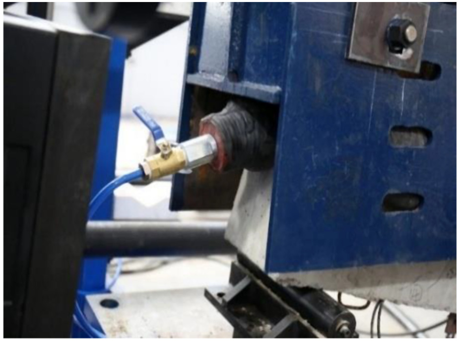
To monitor changes in the strain of the steel reinforcement during the test process, three resistance strain gages (ε1, ε2, and ε3) were attached to the surface of the longitudinal steel reinforcements at the mid-span section and 1/5 sections of the beam length from the end, respectively. Three electronic displacement meters (i.e. D1, D2, and D3) were installed at the bottom of the test specimens, similar to that of the steel reinforcements in the direction of the span length, to record the deflection change of the test beams. The detailed locations of the measurement points are shown in Figure 2. Moreover, a pressure gauge with a maximum measurable pressure of 1.60 MPa was installed at the inlet of the rubber bag, as shown in Figure 8(a). All the test data of the measurement points were automatically collected using a DH-3820 data acquisition system, as shown in Figure 8(b). In addition, the displacement-controlled loading method for the actuator was employed with a loading speed of 0.04 mm/s during the entire test process. It should be noted that the test process will be stopped when the concrete at the top part of the RC beam is crushed, or the test RC beam may present a safety risk that is not suitable for continual loading.

Test setups and instruments: (a) shock pressure gauge and (b) data collection system.
Results and discussion
Responses of RC beams
The typical concrete crushing failure mode was observed for all the test beams, as shown in Figure 9. At the early stages of the test, the concrete at the bottom of the test beams was first cracked when the external load reached the crack strength. Thereafter, the concrete cracks were gradually propagated toward both ends of the test beam in accordance with an increase in the load. The longitudinal steel reinforcement at the mid-span section then yielded, followed by an abrupt increase in the deflection of the test beam, and the rapid propagation of the concrete crack toward the compression zone. Finally, the concrete in the compression zone of the RC beam at the mid-span section was crushed, and the test beam was broken.

Failure model and crack distribution: (a) air bag loading, (b) water bag loading, and (c) four-point bending loading.
As can be seen from Figure 9, there were differences between the failure morphologies of the test beams under different loading conditions. For the air bag loading and water bag loading, the loads on the surfaces of the concrete beam were similar to the uniform load, and the bending moment was parabolic. Hence, the cracks in the concrete of beams A1, A2, A3, and W1 first occurred at the bottom of the mid-span section and then gradually expanded outward from the mid-span section in accordance with an increase in the external forces. The cracks in these beams were mainly concentrated near the mid-span section. The lengths of the concrete crack zones of beams A1 and W1 were 807 and 833 mm, respectively, as shown in Figure 9(a) and (b). However, for the four-point bending loading, the pure bending section was situated between the two loading points at the middle of the concrete beam. The bending moment of the beam in the pure bending section was equal, and the length of crack zone of the beam was found to be mainly dependent on the length of the pure bending section. Therefore, the cracks were first generated at the bottom of the pure bending zone, with almost the same crack spacing for beam F1. The length of the concrete crack zone of beam F1 was 1085 mm, as shown in Figure 9(c). The test results demonstrated the different flexural performances of the RC beams under different loading conditions. It should be noted that the length of concrete crack zone for the test beam under the air bag/water bag load is smaller than that of the four-point bending load. The reason is that when 0.2 < x/L < 0.8, the bending moment of the test beam under the four-point loading method was larger than that of the air bag loading method at the same section. Where x is the distance from the left end section of the test beam and L is the length of RC beam.
Figure 10 presents the curves of the actuator load Fa and mid-span displacement Ur of the RC beams. It can be seen that when the external load reached 129 kN, the longitudinal steel reinforcements of the test beams occurred due to the air bag load and water bag load, and a sustained increase trend in the load–displacement curves was observed until the failure of the test beams. It should be noted that the air/water bag will be deformed with the deflection increase of the test beam; the larger the vertical load, the bigger the rubber bag deformation. When the vertical load reached the yield strength of the longitudinal steel reinforcement, the deflection of the test beam increase rapidly, and the air/water bag was no exception. With the increase of vertical load, the falling steel distribution beam and the rising beam ends were gradually squeezed together through the water bag joint due to the small diameter of the specific cylinder-shaped rubber bags. This will result in that a large number of the actuator loads were directly transferred to the two end supports through this squeeze instead of the components, and this will continue to the end. Therefore, the bending test was terminated at a deflection of about 100 mm for safety due to the concrete crushing at the top part of the test beam.
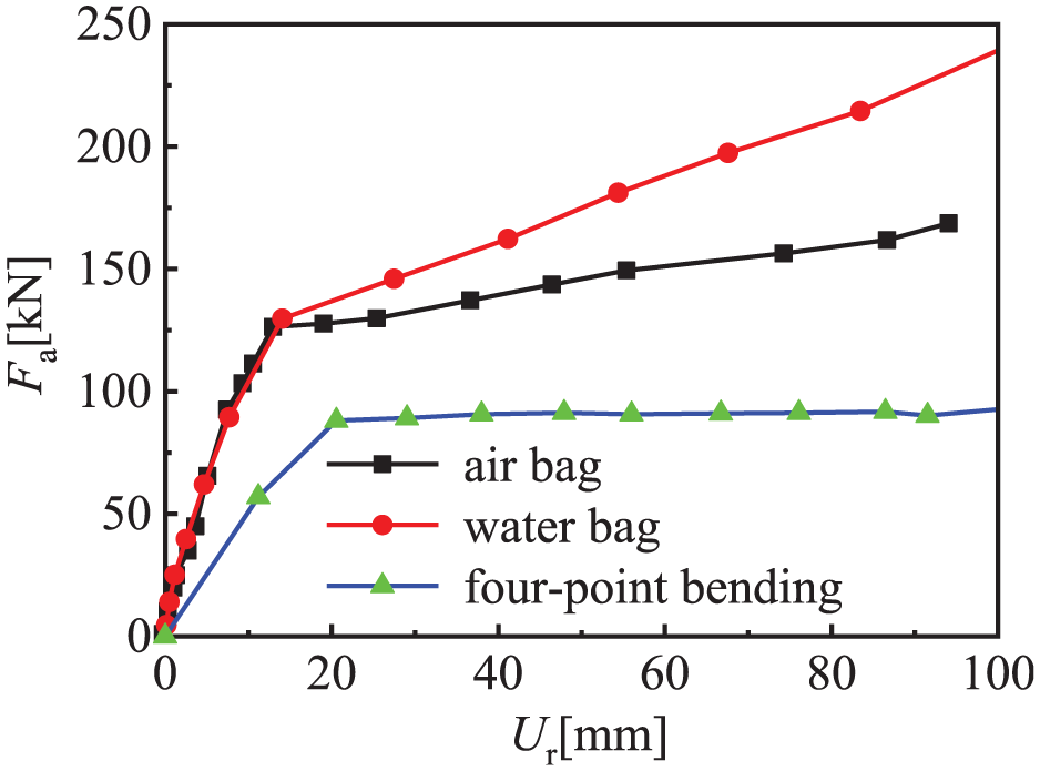
Load–displacement curves of the RC beams.
For beam F1, which was subjected to the four-point bending load, the longitudinal steel reinforcement yielded at 88 kN. Moreover, the load-bearing capacities of the RC beams increased slightly after the yielding of the steel reinforcements, and it generally remained in a horizontally stable state. This occurred because the lengths of the air bag load and the water capsule were larger than the calculated spans of the RC beams, and a negative bending moment was generated at both ends of the RC beams during the test. A detailed illustration is presented below.
With respect to the air bag loading method shown in Figure 11(a), the following equations were obtained
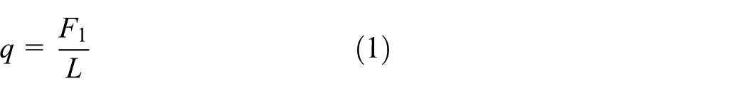

where q is the equivalent uniform load, F1 is the external load under the air bag (water bag) load, Mmax–1 is the maximum bending moment of the RC beam under air bag (water bag) load, L is the length of the RC beam, and a1 and a2 are the distances between the end and support sections, where

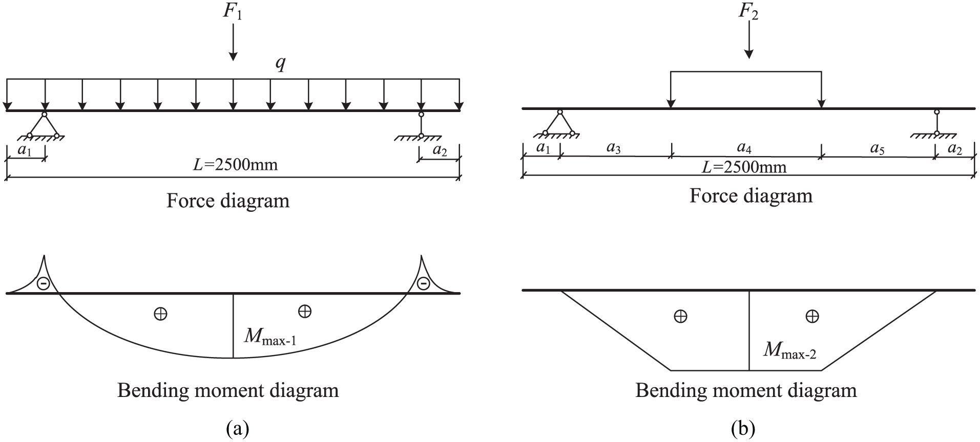
Force diagram and bending moment diagram of RC beams subject to different loading methods: (a) air bag (water bag) load and (b) four-point bending load.
Using the same calculation method as presented above, the maximum bending moment of the RC beam subject to the four-point bending load was obtained as follows
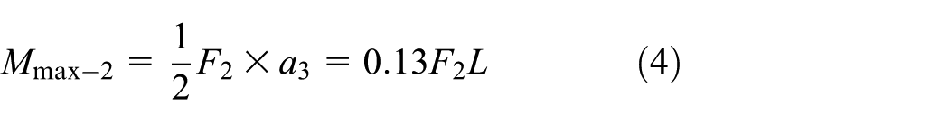
where F2 is the external load of the four-point bending load, Mmax–2 is the maximum bending moment of the RC beam subject to the four-point bending load,
As can be seen from Figure 12, the yield moments of the test specimens were approximately 29 kN m. It should be noted that the yield displacement of the RC beams subject to the air bag and water bag loads were significantly smaller than that subject to the four-point bending load method. After the compression zone of the test, beam enters the plastic deformation stage, the bending moment curves of the RC beam under the air bag/water bag load also tend to increase with the increase of displacement, while the bending moment curves of the RC beam under the four-point loading method basically maintain a horizontal trend of growth. This is because the length of the air bag (water bag) is designed to be larger than the span between the two supports, which is consistent with those subjected to uniform blast loading, and the negative bending moment at the two supports lead to the continuous growth of the bending moment for the test beam. Compared to the air bag loading method after the yield moment, the growth rate of the bending moment for the test beam under the water bag loading method was much higher. This is because the water in the rubber bag gradually gathers toward the middle of the test beam with the increase of the deflection at the mid-span section; this further causes the air at the end of the water bag to be compressed substantially. With the increase of vertical load, the falling steel distribution beam and the rising beam ends are squeezed together through the water bag joint, as shown in Figure 13. This will result in that a large number of the actuator loads were directly transferred to the two end supports through this squeeze instead of the components, which led to the phenomenon that the bending moment of the test beam under the water bag loading method increased faster than that of the air bag loading method after the components yielding.
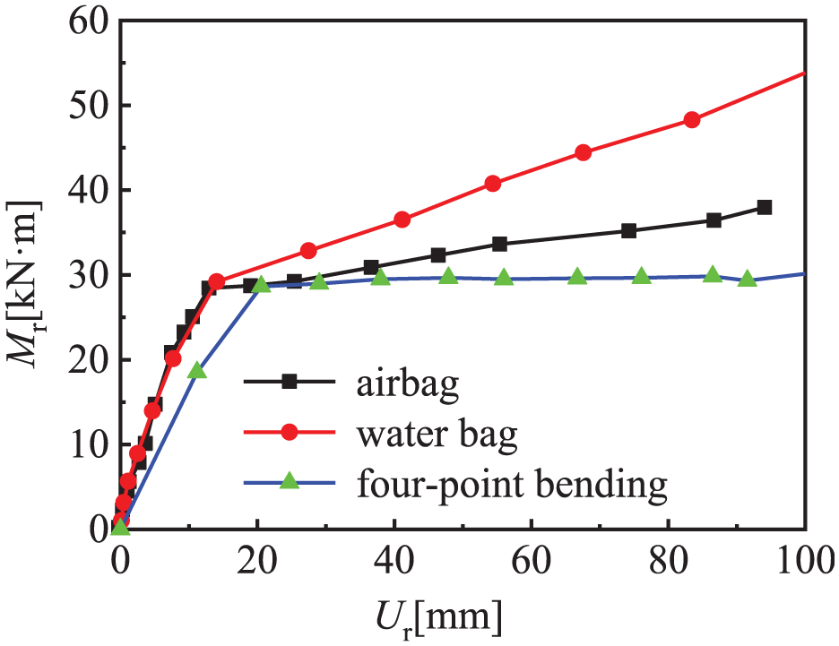
Moment–displacement curve of the RC beams at the mid-span sections.
The end details of the water bag load after the test.
Comparison of loading methods
As is common knowledge, with respect to the dynamic properties of RC structures, the determination of the force–displacement response of RC structures subjected to uniform loads is critical. However, in this study, the rapid decline of the action pressure due to the slight deformation of the air bag load was difficult to determine, due to the low stiffness of the air bag load. Different from the air bag loading method, this effect can be compensated by the water bag loading method. It should be noted that the accidental bursting of the rubber bags occurred, although the rubber bags were all made of solid materials. Compared with the air bag, the water bag was significantly safer due to the higher density of the filled water. Thus, it was more suitable to use the water bag loading method, to obtain uniform loads under laboratory conditions.
Effect of initial pressure on the air bag stiffness
The stiffness of the air bag exhibited a significant influence on the flexural behavior of the test beams; thus, the main focus of this section is on the effect of the initial pressure on the air bag stiffness. At the start of the experiment, the deformations of the test RC beams were relatively small and therefore negligible. Therefore, it was assumed that the straight slope of the actuator load Fa and the actuator displacement Ua is equal to the stiffness of air bag (water bag). The load–displacement curves of the actuator under different loading conditions are shown in Figure 14, and the stiffness of the air bag (water bag) can be expressed with respect to the slopes of the curves. The stiffness of the air bag was found to improve by 123% in accordance with the initial pressure increase from 0.15 to 0.45 MPa. Moreover, the stiffness of the water bag gradually increased in accordance with an increase in the vertical load during the test. This was because air was forced into the water bag during the pumping of water, and the deformation of the water bag at the early stages was mainly due to the compression of the internal air. Thereafter, the stiffness of the water bag gradually increased and then it exceeded that of the air bag. It should be noted that the initial internal pressure of the water was 0.05 MPa, and it was the pressure of the residual air in the water bag.
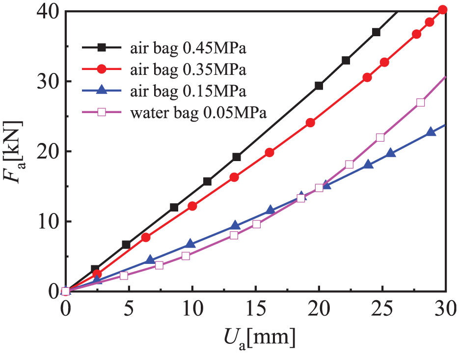
Stiffness comparison between the air bag and water bag.
The higher the initial pressure of the air/water bag, the greater the stiffness of the air/water bag and the better the uniform load distributed. However, the higher the initial pressure of the air/water bag, the higher the performance requirement of the rubber materials (the rubber bag is more likely to be damaged with lower hardness). When the stiffness of the air/water bag is much higher than that of the test beam, the generated load will become non-uniform distribution with the deflection of the test beam. Therefore, an optimal setting for the initial pressure of air/water bag needs to satisfy two conditions: (a) within the ultimate pressure of rubber bag and (b) the stiffness of the air/water bag should be consistent with that of the test beam during the whole deformation process. It should be noted that the stiffness of the test beam is the tangent stiffness that is the tangent modulus of load–displacement curve during the stages of elastic, elastic–plastic, and plastic.
Numerical analysis
Establishment of model
Based on the test results presented above, a numerical analysis model was established using ABAQUS/Standard software. The uniform load was applied to the top surface of the air bag, to simulate the pressure due to the distribution beam, thus simplifying the FEM and reducing the computational load. Two steel baffles were placed on the front and back sides of the rubber bag to prevent the offset or sliding of the rubber bag during the loading process. The air bag was extruded into a box-like shape with the joint actions of the baffles, RC beam, and distribution beam. Hence, the air bag was modeled as a rectangular box for convenience. The detailed FEM of the RC beams under the air-bag load is shown in Figure 15.
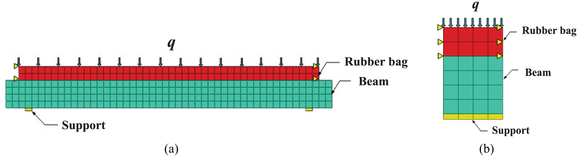
The finite element model of the RC beams under the air bag load: (a) front view and (b) side view.
Material properties and boundary conditions
Until now, many detailed steel constitutive relations have been proposed (Zhang et al., 2016). In this study, the bilinear stress–strain curve developed by the ideal elastic–plastic model in ABAQUS (2009) was adopted for simplicity, as shown in Figure 16. The elastic modulus Es, Poisson’s ratio
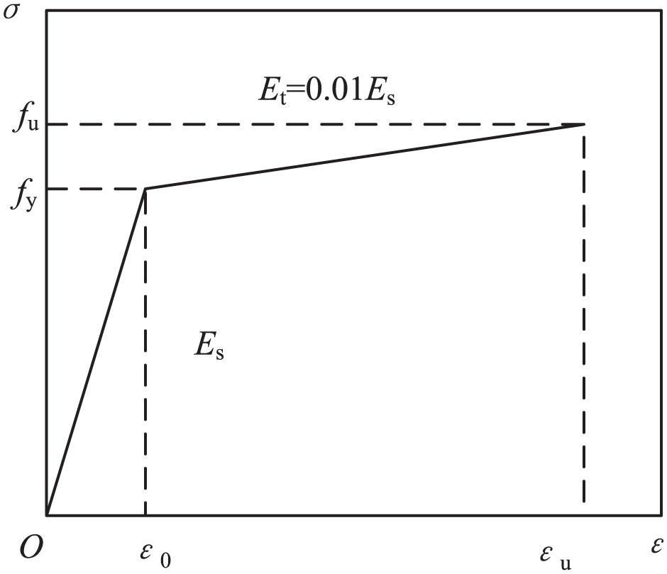
The constitutive model of the steel reinforcement.
According to the material properties of concrete, where tensile strength is far less than the compressive strength, and due to the presence of inelastic response before failure, the Concrete Damaged Plasticity (CDP) model was selected to simulate the stress variation of the concrete. The stress–strain constitutive relationship model of concrete is shown in Figure 17, where
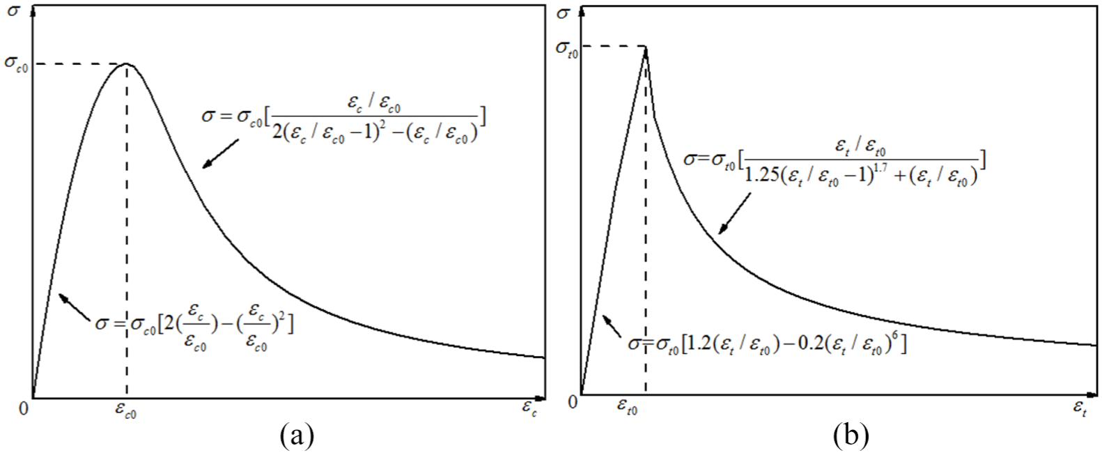
Constitutive relationship model of concrete:(a) compression behavior and (b) tensile behavior.
The elastic modulus and Poisson’s ratio of concrete were given as Es = 4700 × fc0.5 and
Moreover, the solid element and two-node linear three-dimensional (3D) truss hybrid element (T3D2H) were employed, respectively, to model the concrete and steel reinforcements in the FEM.
The rubber bag was discretized using a four-node doubly curved thin or thick shell element (S4R) with reduced integration, hourglass control, and finite membrane strains. The element sizes of the FEM were 50 mm × 50 mm. The isotropic and incompressible material properties were set up for the air bag due to the use of rubber. In addition, the Mooney–Rivlin formula was employed to represent the strain potential, as follows (Wang et al., 2009)
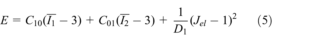
where E is the strain energy of the unit reference volume; C10, C01, and D1 are the material parameters related to temperature; C10 and C01 describe the shear properties of the material; D1 characterizes the material compressibility, where D1 = 0 for rubber materials;
The shell element was selected to model the rubber bags in the FEM. There was a cavity within the rubber bag with a gas constant of 8.31. The cavity was referred to as a “Fluid cavity,” wherein, the specific ambient pressure and molecular weight of the ideal gas were 101.36 kPa and 0.044, respectively (ABAQUS INC., 2013).
A lateral restraint was employed to simulate the enclosures on the front and back sides of the air bag. To accurately simulate the simple supported constraint conditions, small rigid steel blocks with dimensions of 50 mm × 50 mm × 200 mm were respectively set at both ends of the RC beams. The keyword “Friction” was used to describe the contact between the rubber bag and RC beams, and the friction coefficient of this contact was 0.3 (JTG 3362-2018, 2018). In addition, the relative sliding between the RC beam and supports was not considered due to the simple support constraint.
Verification of models
A comparison of the experimental and calculation results of beam A1 is shown in Figure 18. It can be seen that the calculation results were in good agreement with that of the test results. Moreover, the maximum error between the two curves was less than 10%. Therefore, the FEM was effectively used to model the response characteristics of the RC beams subject to the rubber bag load.
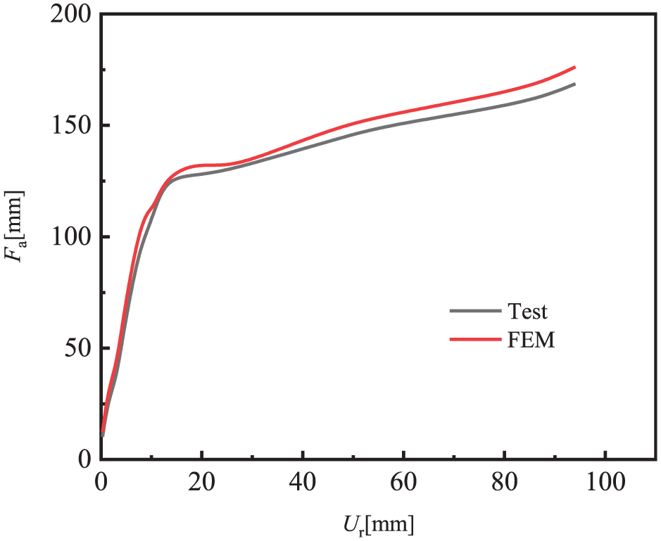
Comparison of test and calculation results.
Discussion of parameters
Boundary constraint
Providing a boundary constraint for the rubber bag can improve its ultimate load capacity. In this study, double-sided constraints and four-sided constraints were applied. Figure 19 presents the support reaction–deflection curves under different constraints. The double-sided constraints were tested as a standard group. The FE calculation results shown in Figure 19 were divided by the maximum reaction force and deflection of the double-sided constraints. In particular, the dimensionless procedure was carried out. The rubber bag was found to have a weak loading capacity without boundary constraints. In addition, there was a significant increase in the load capacity of the rubber bag when the double-sided constraint was applied; however, it was significantly less than that of the four-sided constraint. It is therefore necessary to restrict the boundary constraints of the rubber bag in accordance with the actual situation.
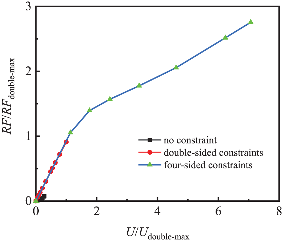
Support reaction–deflection curve of RC beams under different boundary constraints.
The parameters of the rubber material
A fundamental parameter in the design of rubber components is the shear modulus, and it is related to the hardness and composition of rubber. The relationship between the elastic modulus E0, shear modulus G, and material constants C10 and C01 was obtained as follows, when the small strain was generated in the rubber materials (Freakley, 1978; Wei et al., 2014)
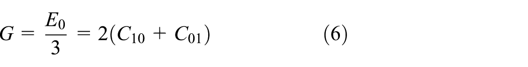
By substituting the experimental hardness H and elastic modulus E0 into equation (6), the following relationship was obtained (Lee and Fenves, 1998)

Therefore, the relationship between the hardness and the sum of C10 and C01 was determined using equations (6) and (7). To investigate the effect of the rubber hardness on the response characteristics of the RC beams, the sum of C10 and C01 was changed. In particular, 4 × 10⁶, 4 × 10⁷, 4 × 10⁸, and 4 × 10⁹ were set as the sums of C10 and C01 in the FEM during the simulation. Moreover, C10 + C01 = 4 × 10⁹ and the FE results were dimensionless. A comparison of the test and calculation support reaction–deflection curves of the RC beams is shown in Figure 20. When C10 + C01 = 4 × 10⁷, the support reaction–deflection curves of the RC beams subjected to the rubber bag load at the mid-span section were closest to that subjected to the ideal uniform load.
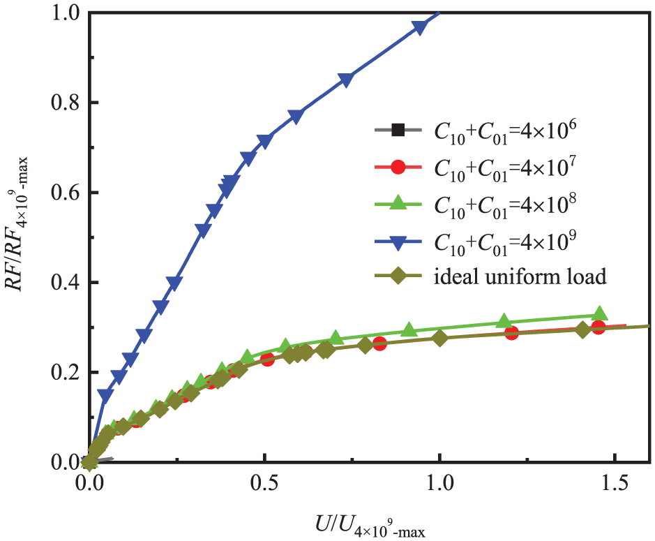
Support reaction–deflection curve of RC beam.
Under a certain external load, the hardness of rubber is closely related to the pressure distribution. With a decrease in the hardness of the rubber bag, there is an increase in the uniformity of the load distribution. However, when the hardness of the rubber bag is excessively small, the rubber bag is easily damaged. Therefore, an appropriate hardness of the rubber bag should be selected based on the actual load and characteristics of the test specimens, for the numerical calculations.
Conclusion
In this study, a bending test was conducted on five RC beams under uniform load, as applied by a rubber bag filled with air or water, to investigate their flexural behaviors. A FEM of the test loading system was established using ABAQUS/Standard software. Moreover, the critical factors of the air bag loading method were analyzed using the numerical model. The main conclusions were as follows:
The uniform load can be obtained using both the air bag loading and water bag loading methods. Moreover, the concrete crushing failure mode was observed for all the test beams subjected to the three different loading methods.
The accidental bursting of rubber bags occurred, although the rubber bags were all made of solid materials. Compared with the air bag, the water bag was significantly safer due to the higher density of the filled water. Thus, it was more suitable to use the water bag loading method to obtain the uniform load under the laboratory conditions.
The stiffness of the air bag improved by 123% in accordance with the initial pressure increase from 0.15 to 0.45 MPa. Given that the water bag contained a slight amount of air, the stiffness of the water bag gradually increased in accordance with an increase in the vertical load during the test.
The FEM of the RC beams subjected to the air bag loading method was established and verified in this study. The FEM can be used to accurately model the response characteristics of RC beams subject to the rubber bag load.
The boundary constraints have a significant influence on the ultimate bearing capacity of rubber bags. It was found that the bearing capacity of the rubber bag can be significantly improved using the four-sided constraints. In addition, the high-hardness rubber bag exhibited a high bearing capacity; however, the uniform distribution effect of the load was poorer than that of the low-hardness rubber bag. Therefore, in general, it is recommended to use low-hardness rubber bags to better achieve a uniform load. However, when the external load is high, four-sided boundary condition and high-hardness rubber bag should be employed.
Footnotes
Declaration of Conflicting Interests
The author(s) declared no potential conflicts of interest with respect to the research, authorship, and/or publication of this article.
Funding
The author(s) disclosed receipt of the following financial support for the research, authorship, and/or publication of this article: The authors would like to express their gratitude to the funding support from the National Fund for Outstanding Youth (Grant No. 51622812), key project of National Natural Science Foundation of China (Grant No. 51738011), and Postdoctoral Fund of Jiangsu Province (Grant No. 2018K087B).