
Abstract
In this article, the rotational behavior of typical bolted glulam beam-to-column connections with slotted-in steel plate was studied in the numerical method. In order to describe the complicated behavior of wood more closely, an elastic–plastic damage constitutive law combining the Hill yielding criterion and a modified Hashin failure criterion was embedded in the commercial ABAQUS software in the form of a VUMAT subroutine. Subsequently, a three-dimensional finite element model based on the constitutive law proposed was established, with the failure mode and moment–rotation curve compared to some similar experiments. Based on this finite element model, a parametric study concentrating on the influence of the width of the beam, bolt diameter, and assembly clearance was carried out. It was found that the numerical method using the proposed constitutive law showed a good capacity to study the rotational behavior of the connections. Besides, the initial rotational stiffness increased with the increase in beam width and bolt diameter, and the assembly clearances between bolts and bolt holes would affect the initial rotational stiffness while the assembly clearance between beam and column affected little.
Keywords
Introduction
In timber structure, the bolted connection with slotted-in steel plate—with a greater fire safety, better aesthetic appearance, easy fabrication, and installation—is widely used nowadays. Nevertheless, this connection—which is able to transfer the bending moment partially, namely, the semirigid behavior—is conservatively considered as hinge due to its complex force transfer. In fact, this assumption, especially for beam-to-column connections, is not precise and could lead to an inaccurate result of the internal forces in structures, which makes the structural design undependable. Therefore, it is essential to thoroughly study the semirigid behavior of the bolted glulam connections with slotted-in steel plate and propose a precise method for structural design.
At present, a majority of the studies on the bolted glulam connections use the experimental method (Gattesco and Toffolo, 2004; He et al., 2011; Wang et al., 2015; Xu et al., 2011). However, the experimental research is time-consuming and difficult to consider all the parameters comprehensively. In this case, the numerical method is combined for further research. Bouchair et al. (2007) developed a two-dimensional finite element model to describe the behavior of a T-shaped timber–timber joint with the dowels in a circular pattern. It was found that the geometrical center of the bolt pattern assumed to be the mechanical rotational center of the joint was feasible, and it was necessary to take the effect of the interaction between the shear and the tension perpendicular to grain into consideration. Since the complex anisotropic behavior of wood in different loading directions, which is related to the failure mode of the joint, it is necessary to adopt an appropriate constitutive law in the finite element model for a better simulation. Xu et al. (2009a, 2009b) proposed numerical approaches for dowel-type timber joints, taking the plastic yielding and damage evolution of timber into account using the Hill yielding criterion and the Hoffman failure criterion. The numerical results were in a good agreement with the experimental results. Wang et al. (2019) established a finite element model including a yielding criterion, an associated flow rule, and a hardening rule to capture the anisotropic behavior of timber. By means of a user-defined subroutine UMAT (user-defined material), this model was set up in ABAQUS to analyze the behavior of bolted glulam beam-to-column connections under shear and bending. It is noticed that a precise and implementable constitutive law can provide an effective verification when studying the rotational behavior of timber connections.
According to the earlier research works (Wang et al., 2019; Xu et al., 2009a, 2009b), the Hill yielding criterion (Hill, 1948) is an effective law to detect the yield of wood. When it comes to the brittle failure, a series of criteria have been proposed in present research works, but the implementation of the criterion in the finite element calculation cannot be ignored. Some researchers have used or proposed criteria to simulate the mechanical behavior of wood. Chen et al. (2011) used the Yamada–Sun criterion (Yamada and Sun, 1978) to judge the damage of wood, which separated the yield judgment of different directions of wood. However, this criterion is little complex with the difference in the tangential and radial properties considered when modeling the timber connections. Xu et al. (2014) proposed a modified Hill criterion and applied it into the simulation of dowel-type connections and found that this criterion is valid to judge the failure of wood by comparison to the experiments. Sandhaas (2012) proposed a criterion based on the assumption that wood is an anisotropic material, which is complex with eight failure modes. When Wang et al. (2019) used this failure criterion with the wood assumed as an orthotropic material, the number of failure modes is reduced. However, when dealing with the problem of rotational behavior of the bolted glulam beam-to-column connections, the method is still complicated and relatively inefficient.
In this article, a typical configuration of bolted glulam beam-to-column connections is studied in the finite element method. By summarizing the previous research results, an elastic–plastic damage constitutive law using the Hill yielding criterion associated with a modified Hashin failure criterion (Hill-modified Hashin criterion) to predict the plastic yielding and damage evolution is proposed and implemented by a VUMAT (vectorized user-defined material) subroutine in ABAQUS. The typical connections are modeled considering the constitutive law mentioned earlier and verified by existing similar experimental results. Finally, this modeling strategy is used to achieve the influence of the width of the beam, bolt diameter, and assembly clearance on the initial rotational stiffness and stiffness degradation rate of this kind of connections.
Constitutive model of wood
A VUMAT subroutine programmed in FORTRAN language is used in this article to define the elastic–plastic damage constitutive law of wood in ABAQUS. At the elastic stage, wood is assumed as an orthotropic material. When the stress increases to a certain threshold where the deformation under compression and tension becomes different, namely, the post-elastic stage, it is assumed that the wood exhibits plastic failure when under compression parallel and perpendicular to grain at the same time (compression–compression), and the plastic yield surface changes continuously with the generation of plastic flow. In other cases, such as under compression parallel to grain while tension perpendicular to grain (compression–tension), under tension parallel to grain while compression parallel to grain (tension–compression), or under tension parallel and perpendicular to grain at the same time (tension–tension), the failure of wood is assumed as brittle fracture (Mackenzie-Helnwein et al., 2005; Sandhaas, 2012; Xu et al., 2009b). In addition, the Hill-modified Hashin criterion is proposed to describe the damage evolution of wood. This method makes up for the deficiency of the Hill yielding criterion without considering the difference of strength between tension and compression, and it is easier in the simulation of damage evolution. The combined criterion is illustrated in Figure 1, where the dashed line represents the boundary of the Hill yielding criterion, while the solid line is the envelope of the modified Hashin failure criterion. ft,0, fc,0, ft,90, and fc,90 are the tensile and compressive strengths of wood parallel to grain and perpendicular to grain, respectively.
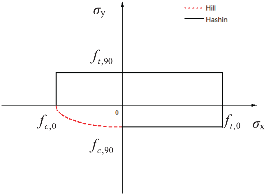
Envelope of the two criteria.
The main novelty of this constitutive model is the proposed modified Hashin failure criterion, which is not only an easy-implementing but also an effective model to describe the failure of wood. At the elastic stage, the stress–strain formula can be written as

where

and
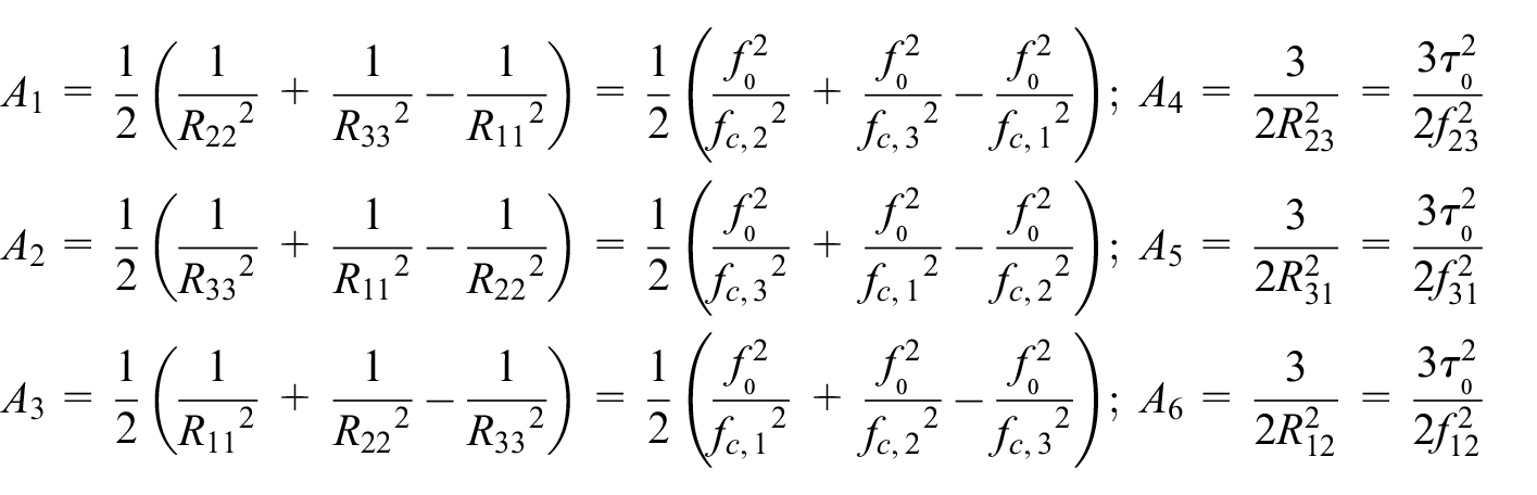
where Ri,
j
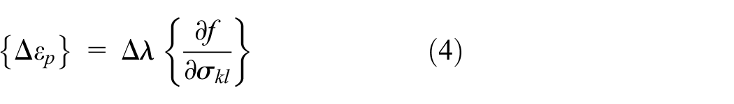
= (i,j = 1, 2, and 3) are the anisotropic coefficients, and the subscripts i and j are the stresses along the principal axes, with i,j = 1, 2, and 3 denoting the longitudinal, radial, and tangential directions, respectively. At the plastic stage, the strain increment

The consistent tangent modulus method (Simo and Taylor, 1985), which has a better convergence speed, is used to derive the stress updating of anisotropic materials at the plastic stage. According to the Drucker postulate, the plastic strain increment can be expressed as
where
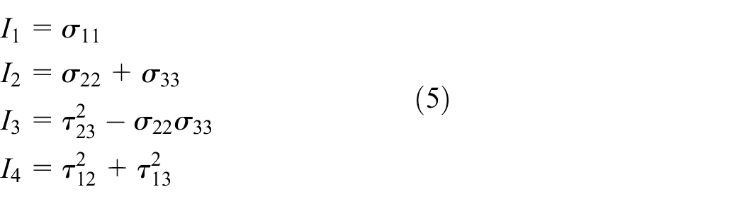
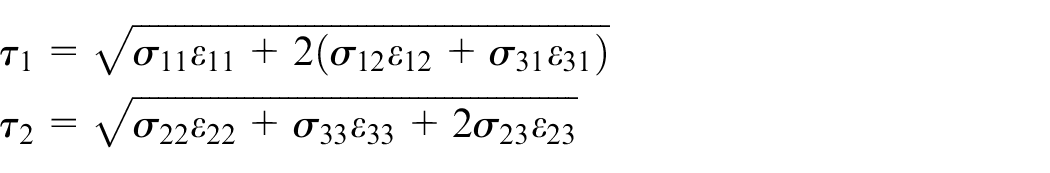
Referring to the Yamada–Sun criterion, the modified failure criterion can be obtained
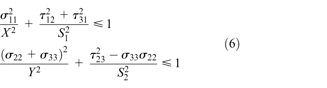
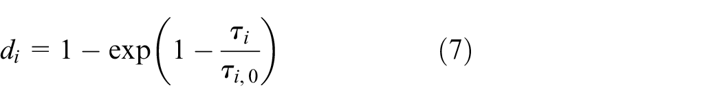
where X and Y are the tensile or compressive strength parallel and perpendicular to grain, respectively. S1 and S2 are the longitudinal shear strength and the tangential shear strength, respectively. At the damage evolution stage, the continuum damage mechanics theory (Krajcinovic and Lemaitre, 1987) is used to describe the wood softening behavior. In order to satisfy the failure criterion (equation (6)) where the material damage in each principal axis is affected by the corresponding shear stress, a formula for calculating the damage variable is constructed as follows—based on the theoretical model of damage accumulation for isotropic materials proposed by Simo and Ju (1987)
and
where di is a damage parameter, with the values ranging from 0 to 1. di = 0 means that the material is undamaged, and di = 1 means that the material is completely damaged. Besides, the wood damage is irreversible, so at the damage evolution stage, there is always a relation,
Finite element model
To describe the rotational behavior of a typical bolted connection, with one steel plate both slotted into the beam and the column, three-dimensional (3D) finite element models are established in ABAQUS based on the constitutive law mentioned earlier and verified by the experimental results.
Connection model configurations
The detailed configuration of the connection is illustrated in Figure 2. The components of the connection include as follows: the glulam beam (130 mm × 305 mm in cross section), the glulam column (272 mm × 305 mm in cross section), bolts (20 mm in diameter), and slotted-in steel plate (9.5 mm in thickness). Besides, the bolt holes on the glulam and the steel plates are 2 mm larger than the bolt diameter, and there is 5 mm clearance between the beam and the column, which are all considered in the finite element models (Figure 3).
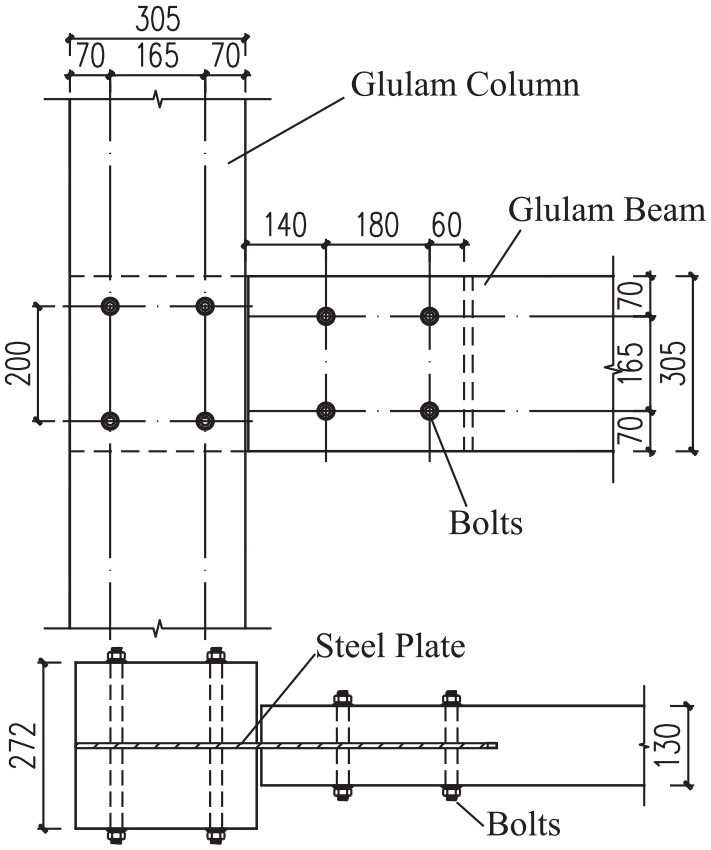
Detailed configuration of the specimen.
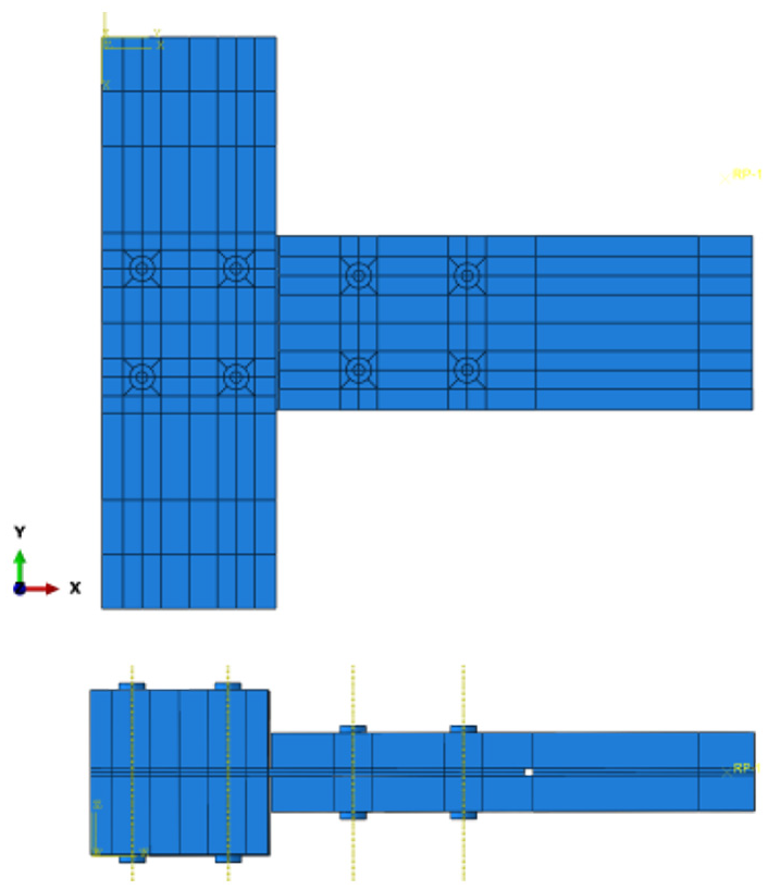
Finite element model.
Development of the connection model
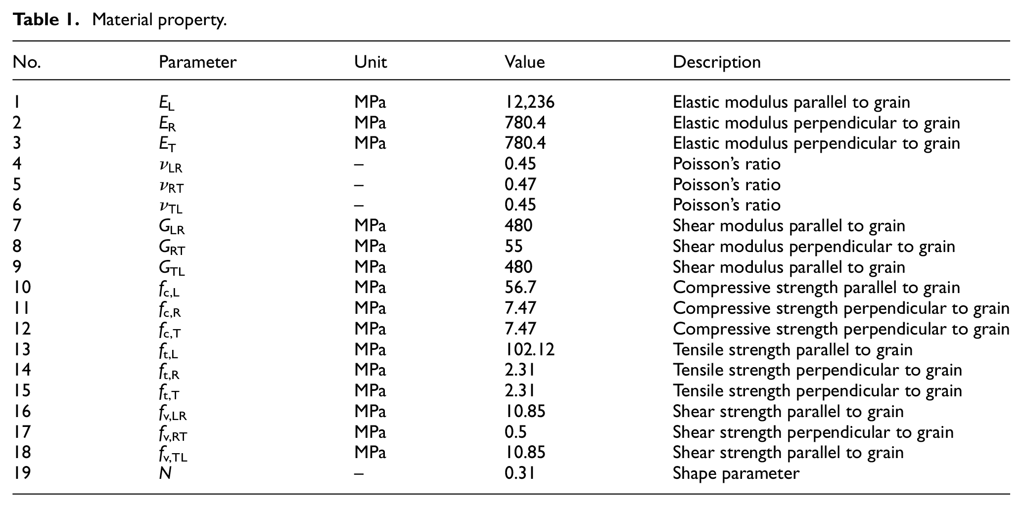
For material, the constitutive law of wood is mentioned earlier. The strain hardening perpendicular to grain and the damage evolution under compression parallel to grain of the wood are ignored. The material property of the wood is listed in Table 1, which is from the material test in the previous study (Sun, 2014) and Qiu’s (2015) thesis. Besides, the yield strength of Q345 grade steel and 8.8 grade bolt is 345 and 640 MPa, respectively, submitting to the bi-linear model. The elastic modulus of steel is 2.06 × 10⁵ MPa and the Poisson ratio is 0.3.
Material property.
Each contact pair is defined by face-to-face contact and set as finite sliding. In tangential contact, friction coefficient is set, and the friction coefficient between wood and bolts, wood and steel plate, bolts and steel plate, and wood and wood is 0.6, 0.1, 0.2, and 0.5, respectively (Sjodin et al., 2008). Due to the assembly clearance in this model, a connect-point-to-ground spring element with a small stiffness is established to eliminate the rigid body displacement before the components contact with each other. The C3D8R element is adopted due to the high nonlinearity of the material and the large strain of the elements after failure. The hexahedral element is used to mesh the model, and the vicinity of the bolt holes is refined, as shown in Figure 4. By assigning a status variable, state = 1, and setting the max degradation value to 0.8, the elements whose damage parameter is larger than 0.8 are deleted in the post-processing.
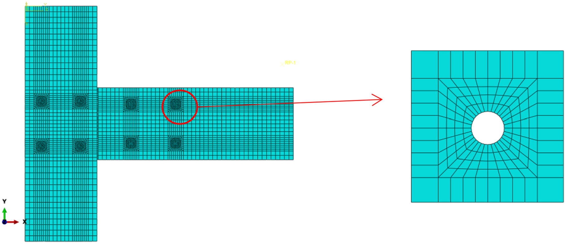
Meshing of the connection.
Considering the actual situation of the experiment, fixed boundary conditions are set at the top and bottom of the glulam column. Meanwhile, the out-of-plane constraint on the central surface of the model is set. Two steps are set when loading to make sure the stability of the whole model in analysis. In the first step, load control is adopted, that is, a small load is applied to the loading point to make sure the components’ contact stably. In the second step, displacement control is adopted.
Numerical results and analysis
To validate the finite element model, the failure mode and the moment–rotation curves are compared to some experimental results (Lam et al., 2008; Lu et al., 2016; Wang et al., 2014). Furthermore, the equivalent stress distribution of the wood is analyzed when the splitting failure happens, and the force development of each bolt hole is studied by comparing the contact forces in different steps of ABAQUS. It is referred that the bending moment M equals to the applied force multiplied by the distance between the applied force and the geometrical center of column bolts, and θ is the rotation angle between column and beam. Moreover, the initial rotational stiffness k0 and the post-elastic stiffness k1 are defined according to the secant stiffness method (Yasumura and Kawai, 1998), which is provided in equations (8) and (9)
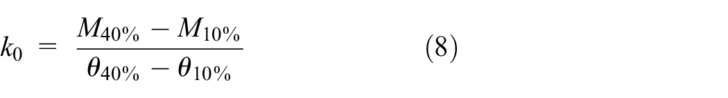
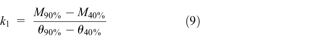
where M10%, M40%, and M90% are the moments equal to 10%, 40%, and 90% of Mu, respectively; θ10%, θ40%, and θ90% are the corresponding rotation angles, respectively; and Mu is the ultimate moment.
Failure mode
The failure modes of the numerical and experimental results are presented in Figure 5. Although the configurations are not entirely consistent with each other, the failure modes are similar. As shown in Figure 5(a), the wood splits, with the related elements deleted, in the vicinity of the bolt holes 1, 2, and 3 when loading to failure. When the applied bending moment comes to 28.8 kN m, perpendicular-to-grain tensile failure happens in the vicinity of bolt holes 2 and 3. With the increase in the bending moment, the vertical crack in the vicinity of bolt hole 2 develops rapidly to bolt hole 1 and will cause split. The failure behavior of the bolt hole 3 is the same, while it grows slower. It is found that the failure mode of the finite element mode is in accordance with that of the experimental specimens.
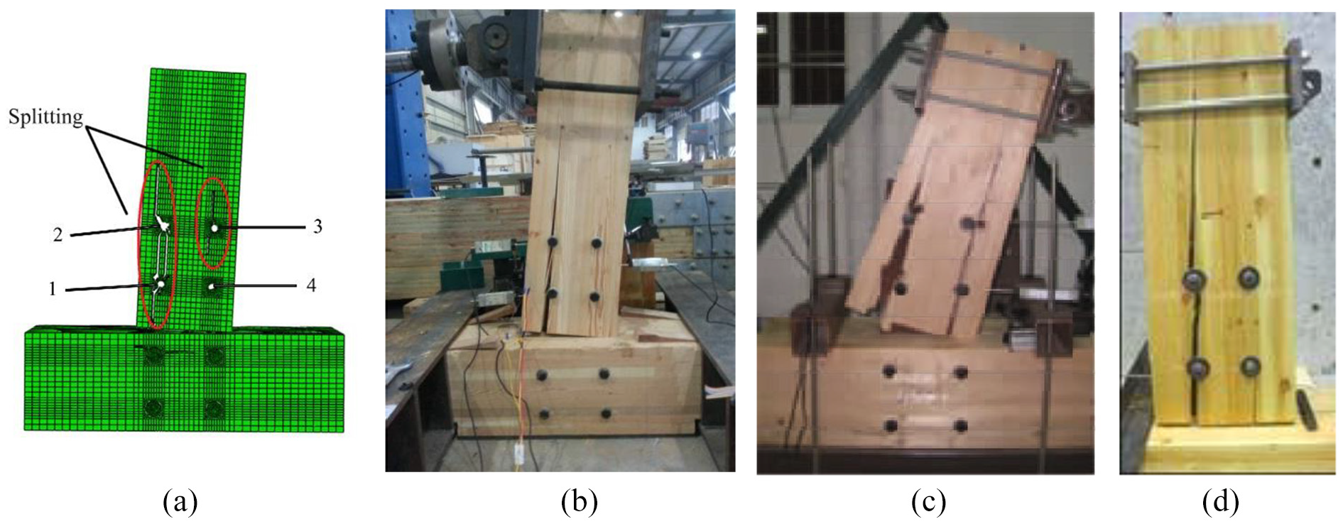
Comparison of the failure modes: (a) finite element model, (b) specimen from Lu et al. (2016), (c) specimen from Wang et al. (2014), and (d) specimen from Lam et al. (2008).
Stress distribution and force development
Figure 6 shows the equivalent stress distribution of the wood when the splitting failure happens. It is noted that stress is concentrated in the vicinity of the bolt holes 1, 2, and 3 and the contact area between the end of beam and the column, which means that the wood near the bolt holes 1, 2, and 3 is already yielding and plastic strain appears, while the stress near the bolt hole 4 remains small. Besides, the equivalent stress of the elements near the cracks is very small, which means that the stress of the deleted elements due to failure decreases dramatically.
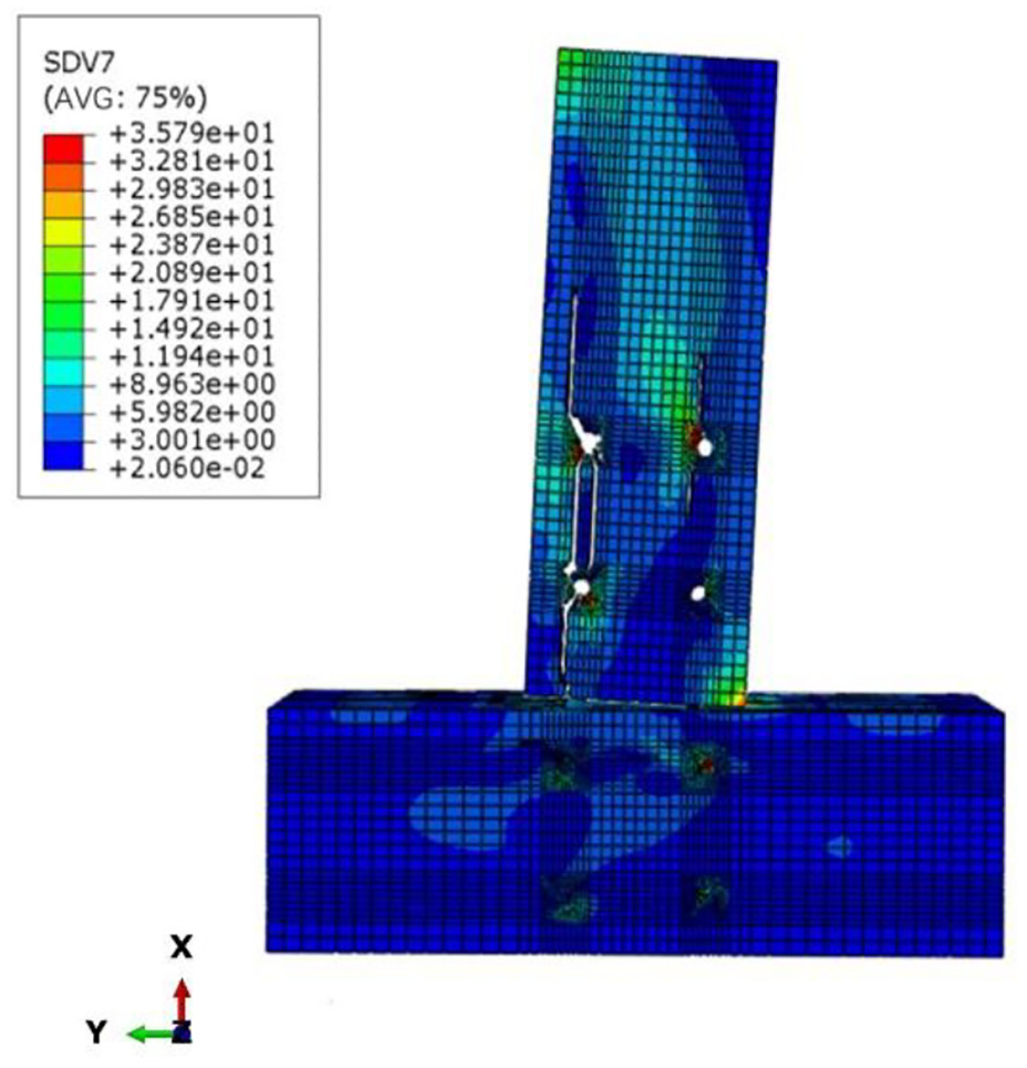
Equivalent stress distribution of the wood.
The contact force of the elements around the bolt holes is extracted and calculated in order to obtain the contact force of the bolt holes (Figure 7(a)), and the resultant force of different holes is shown in Figure 7(b), where the displacement is the actual value in loading step, with a total of 114 mm. It is noted that the contact force of bolt hole 1 increases faster than other bolt holes, while the contact forces of other bolt holes are in a nearly same increasing speed with a relation Fcomp,2 > Fcomp,3 > Fcomp,4. Figure 7(c) and (d) shows the component contact force near each bolt hole in longitudinal direction and radial direction of the beam. It is worthwhile to refer that the contact force of bolt hole 1 increases mainly along the longitudinal direction, while that of the bolt holes 2, 3, and 4 increases along the radial direction mostly. Thus, it is concluded that the rotational center is gradually shifting to the bottom right corner and tending to be stable with the increase in applied displacement.
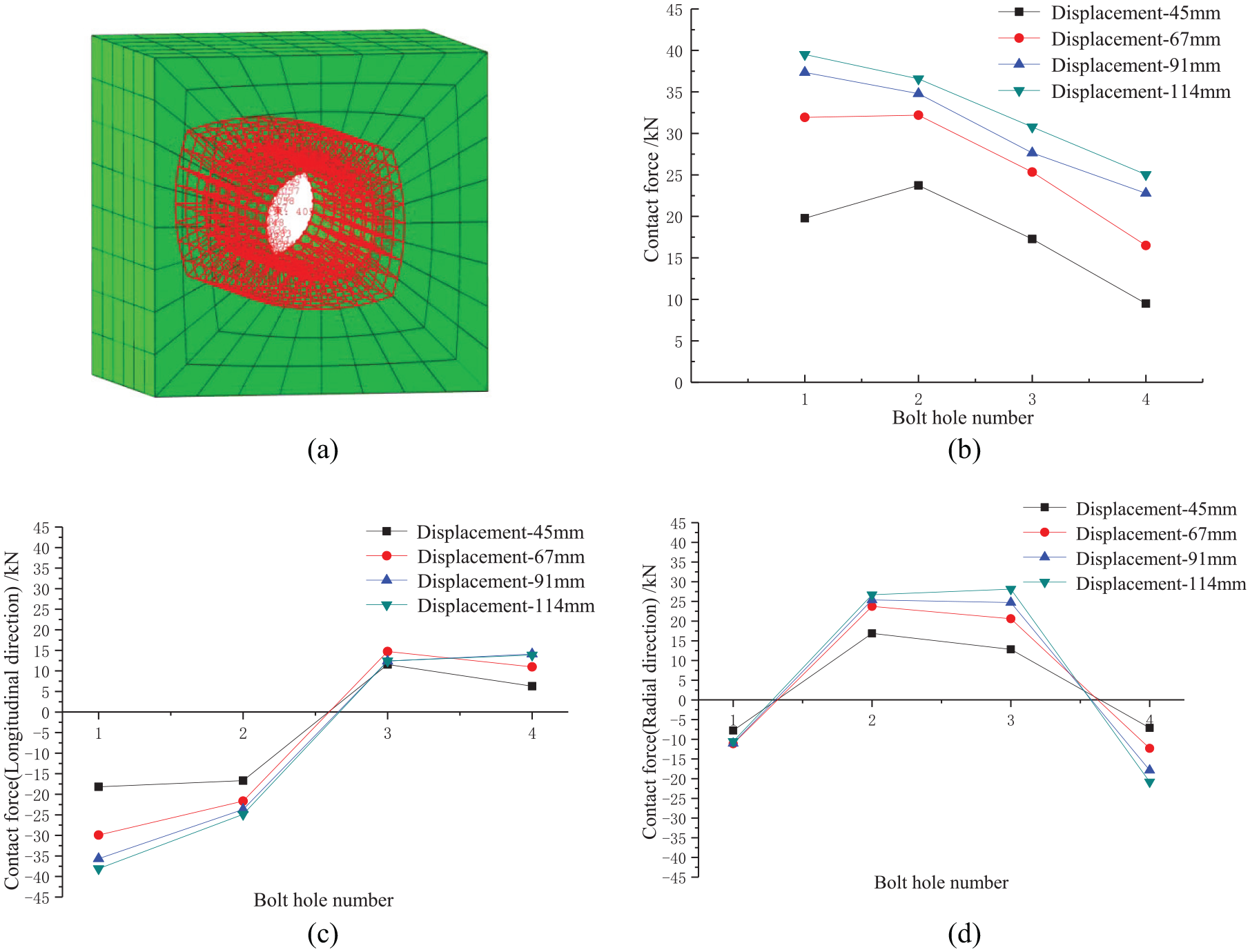
Distribution of contact force of the bolt holes: (a) extracted elements around the bolt holes, (b) resultant contact force of bolt holes, (c) contact force in longitudinal direction, and (d) contact force in radial direction.
Moment–rotation curves
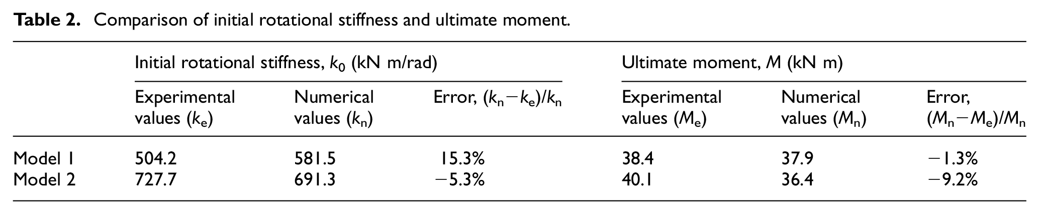
Two models with different bolt diameters of 20 and 24 mm are established according to the specimens. The comparison of the experimental and numerical moment–rotation curves under monotonic loading is given in Figure 8. Observing the curve shape, initial rotational stiffness, and stiffness degradation, the numerical results are in a good agreement with the experimental results. Besides, the comparison of the initial rotational stiffness and ultimate moment is given in Table 2, which shows an acceptable error. Therefore, the developed finite element model could be an effective tool for further research.
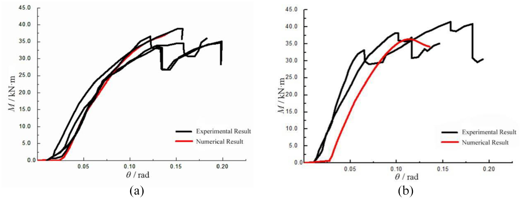
Moment–rotation curve: (a) model 1 (d = 20 mm) and (b) model 2 (d = 24 mm).
Comparison of initial rotational stiffness and ultimate moment.
Parametric analysis
Based on the model in Figure 3, a series of parameters—including width of the glulam beam, bolt diameter, and assembly clearance—are modified to evaluate the influence on the initial rotational stiffness. The widths of glulam beam and bolt diameter are critical factors as many researchers have proposed. Besides, the assembly clearance does not attract much attention in the experimental study. The models in this section are named as W-130-D-20, where W-130 is the width of beam and D-20 is the bolt diameter.
Influence of the width of the glulam beam
To quantify the influence of the beam width on the initial rotational stiffness, the connection with the glulam beam of different widths (130, 170, 210, and 250 mm) is modeled. Figure 9 compares the moment–rotation curves of the models with different beam widths, and the bolt diameter is 20 mm. It can be seen that the greater the width of the glulam beam, the greater the ultimate bearing capacity of the connection, and the slower the stiffness degradation after yielding. The overall ductility is improved with the increase in beam width. The comparison of the initial rotational stiffness of the models with different beam widths is concluded in Figure 10, where the values are grouped by bolt diameters. It is found that each time when the width of beam increases 40 mm, the initial rotational stiffness increases about 3.6%, which shows a slow and steady improvement.
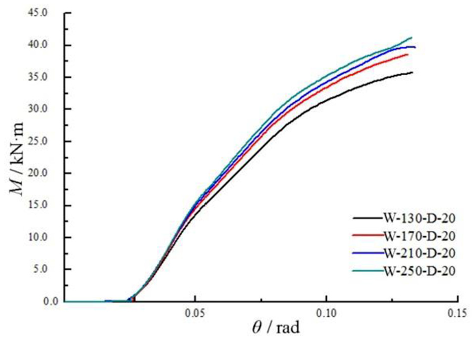
M–θ curves with different beam widths.
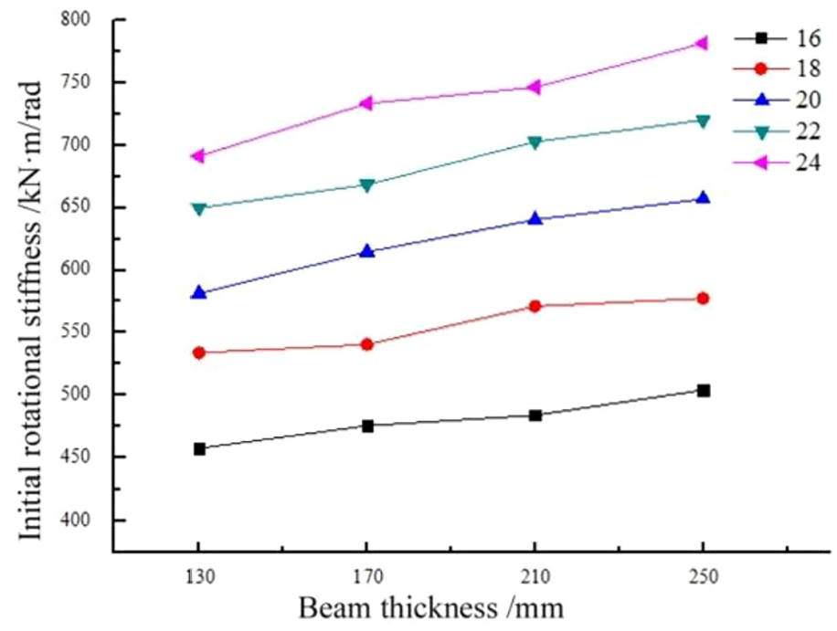
Comparison of initial rotational stiffness with different beam widths.
Influence of the bolt diameter
To study the influence of the bolt diameter, five bolt diameters (16, 18, 20, 22, and 24 mm) are considered and compared, which are frequently arranged in engineering. Similarly, Figure 11 compares the moment–rotation curves of the models with different bolt diameters, and the beam width is 130 mm. It can be seen from these curves that the increase in bolt diameter can greatly improve the initial rotational stiffness and reduce the stiffness degradation of the connection after yielding. Figure 12 shows that the initial rotational stiffness increases by 11.4% on average when the diameter of the bolt increases by 2 mm each time.
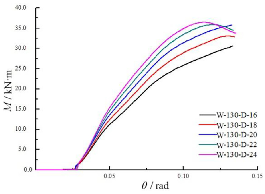
M–θ curves with different bolt diameters.
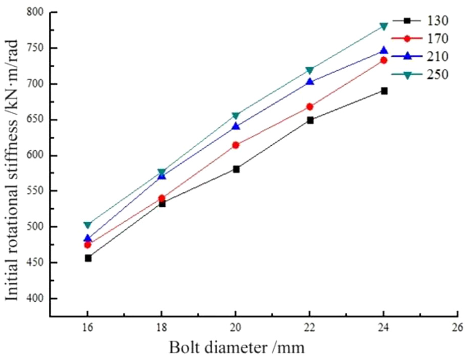
Comparison of initial rotational stiffness with different bolt diameters.
Table 3 presents the stiffness degradation of the models with different beam widths and bolt diameters. It is concluded that the stiffness degradation increases with the increase in bolt diameter while decreases with the increase in beam width, and the stiffness degradation of the models is all ranging from 70% to 80%.
Stiffness degradation rate of each component.
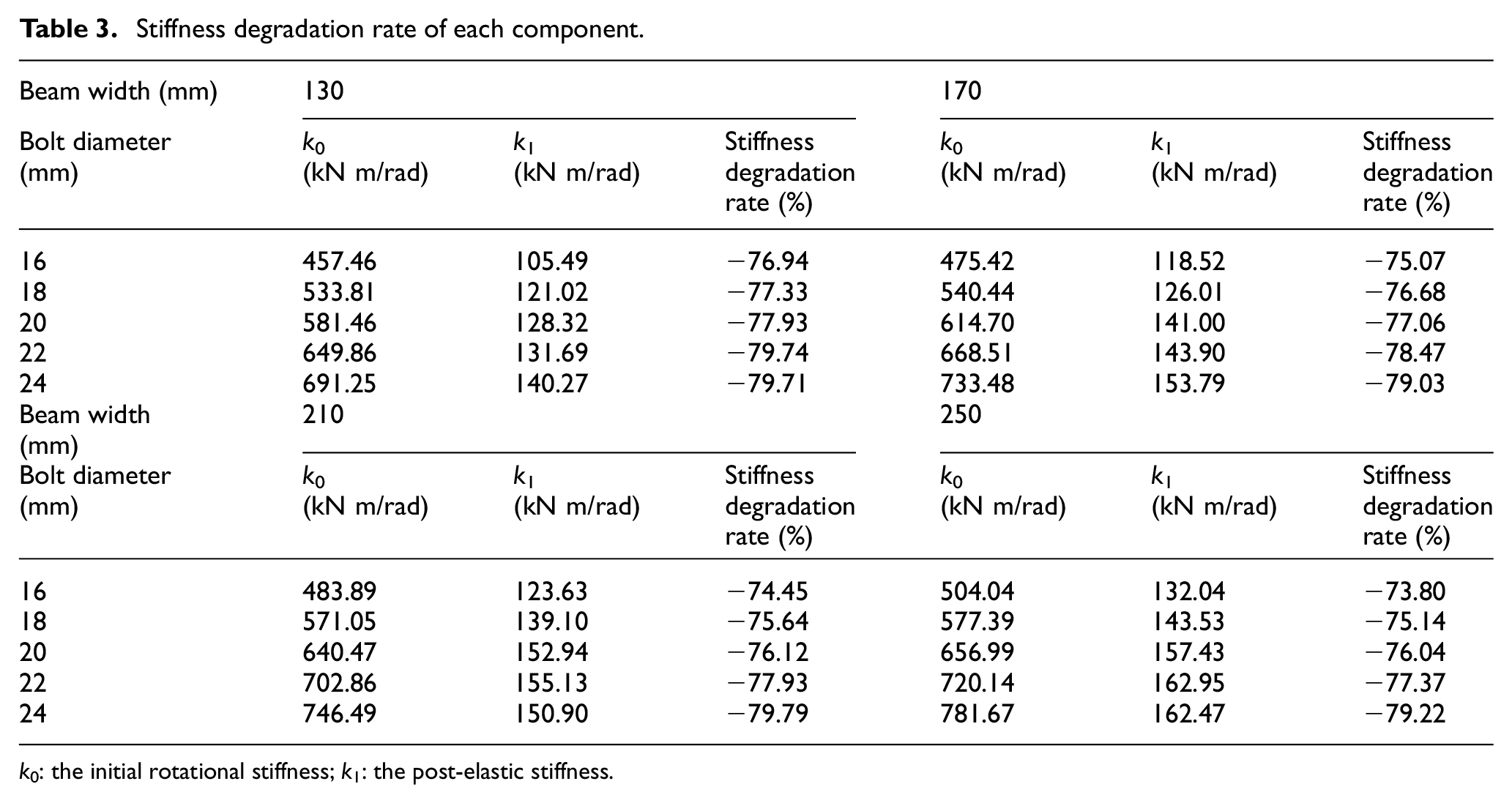
k 0: the initial rotational stiffness; k1: the post-elastic stiffness.
Influence of the assembly clearance
The two kinds of assembly clearances—clearances between bolts and bolt holes, and clearances between beam and column—are considered in this section. Based on the model W-130-D-20, five different assembly clearances—0, 0.5, 1, 1.5, and 2 mm—are considered. It is noticed that the varieties are the diameter of the holes on glulam while the holes on steel plate are not changed, with a value larger than the bolt diameter. As shown in Figure 13, the initial rotational stiffness of the connection without assembly clearances is 18.3% higher than that with clearances on average. Totally, the initial rotational stiffness decreases with assembly clearances increase, while it declines with a steeper trend when the clearances are larger. Besides, the initial rotational stiffness of the connections with or without assembly clearances is quite different.
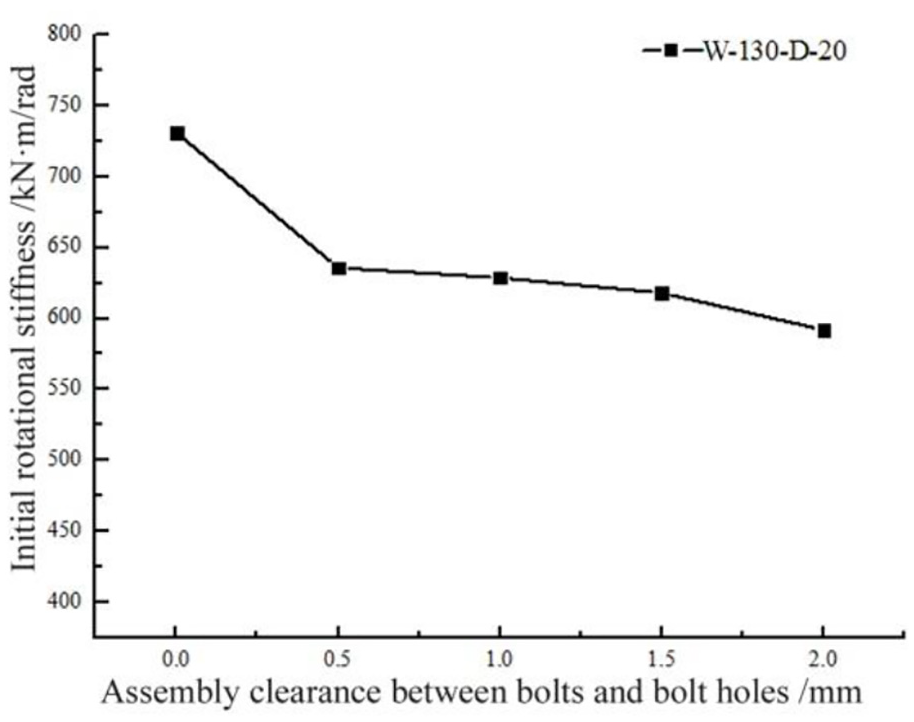
Comparison of initial rotational stiffness with different assembly clearances between bolts and bolt holes.
It can be seen from Figure 14 that the moment–rotation curves of the connections all have a zero-stiffness section, a low-stiffness section, a stiffness lifting section, and a stiffness degradation section regardless of whether there is assembly clearance or not. The zero-stiffness section is generated because the components do not fully contact with each other at the beginning, which is idealistic for reality. The low-stiffness section is generated because the contact area between the bolts and holes is small at the initial rotation stage. With the load increasing, the contact area gradually increases, which leads to the increase in rotational stiffness. Futhermore, the zero-stiffness section becomes longer when the assembly clearances become larger. The stiffness of the low-stiffness section without assembly clearances is 644.68 kN m/rad, and that of the low-stiffness section with assembly clearances is 413.87 kN m/rad. The stiffness of the low-stiffness section without assembly clearances is 35.8% higher than that with assembly clearances.
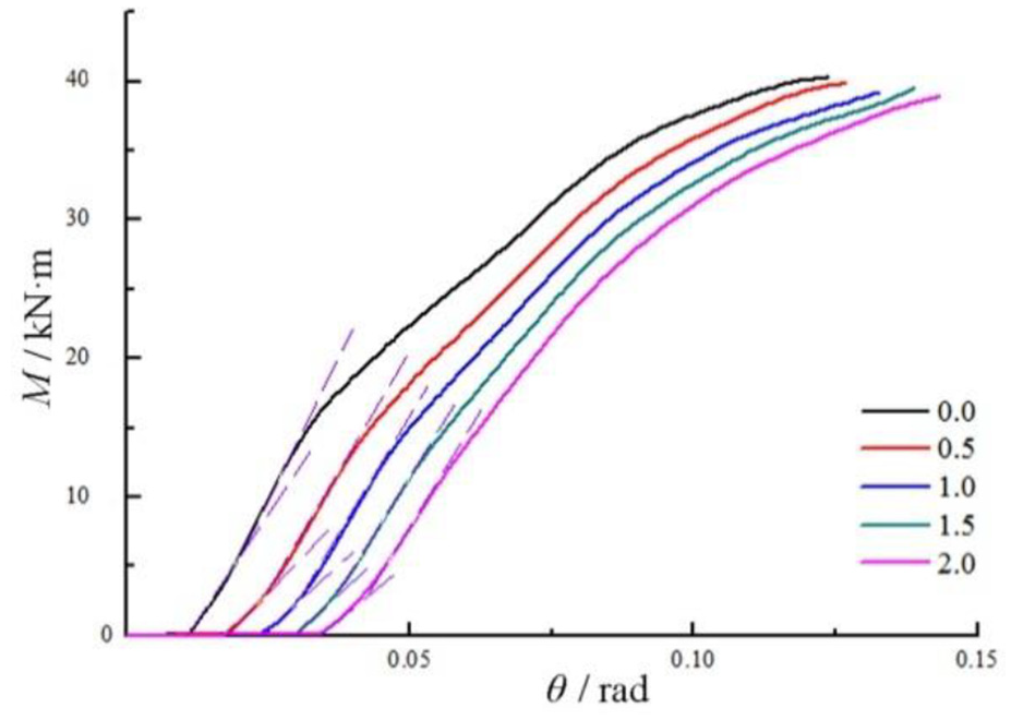
M–θ curves with different assembly clearances between bolts and bolt holes.
On the basis of model W-130-D-20, four models with 0, 5, 10, 15, and 20 mm assembly clearances between beam and column, respectively, are established to investigate the influence of assembly clearances between beam and column on the initial rotational stiffness. It is shown in Figure 15 that the initial rotational stiffness is not sensitive to the installation clearances between beam and column, with a variation of about 2%, while the moment–rotation curves in Figure 16 shows that the assembly clearances have an impact on the stiffness degradation rate. Moreover, the model with 10 mm assembly clearances is able to achieve a better rotational behavior.
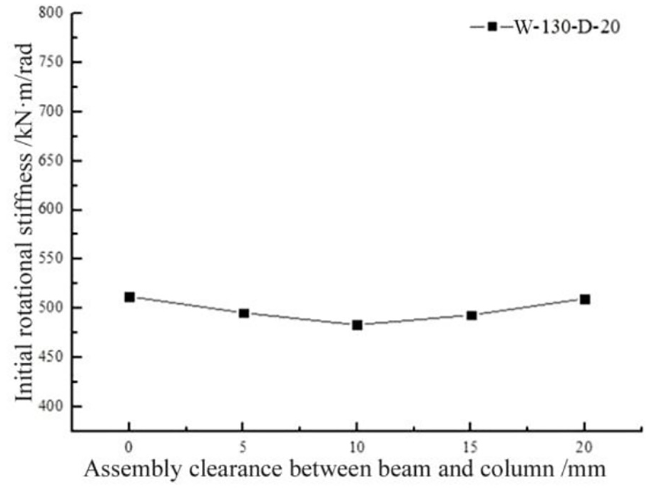
Comparison of initial rotational stiffness with different assembly clearances between beam and column.
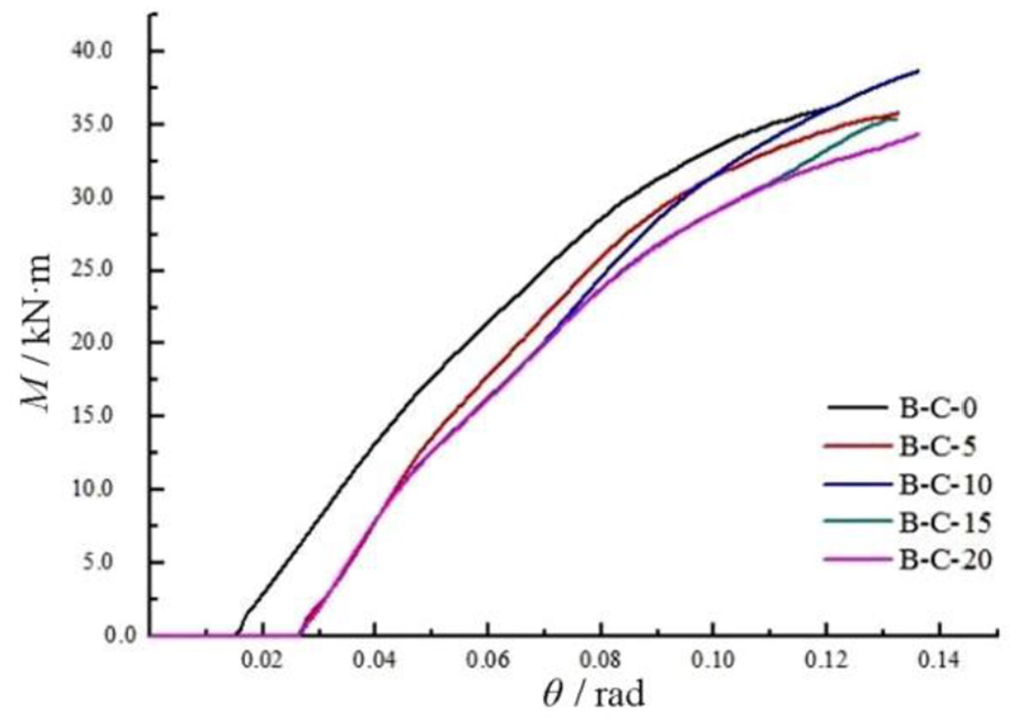
M–θ curves with different assembly clearances between beam and column.
Conclusion
This article presents a finite element method to study the rotational behavior of a typical bolted glulam connection. Based on the investigation, the following conclusions can be drawn:
The numerical results show a good agreement with the experimental results, which means that the numerical method using the proposed Hill-modified Hashin criterion programmed by the VUMAT subroutine in ABAQUS to simulate the behavior of wood is effective in studying the rotational behavior of the bolted connection.
Increasing both the beam width and the bolt diameter can improve the initial rotational stiffness of the connection, while the increase rate induced by beam width is smaller. As to the stiffness degradation after yielding, the stiffness degradation rate decreases with the increase in beam width, but increases with the increase in bolt diameter, with the value ranging from 70% to 80% in general.
The initial rotational stiffness of connections without bolt hole clearance is 18.3% higher than that with clearance on average and shows a nonlinear downward trend with the clearance becoming larger. It is suggested that the bolt hole clearance should be limited at about 1.5 mm, and the maximum should not exceed 2 mm in practical engineering. The assembly clearance between beam and column has no apparent influence on the initial rotational stiffness while it has influence on the stiffness degradation rate.
However, this numerical research is based on a typical bolted beam-to-column connection with a regular steel plate slotted both in the beam and the column, and the applicability for other configurations needs for further research.
Footnotes
Declaration of Conflicting Interests
The author(s) declared no potential conflicts of interest with respect to the research, authorship, and/or publication of this article.
Funding
The author(s) disclosed receipt of the following financial support for the research, authorship, and/or publication of this article: This study was supported by the National Key R&D Program of China with a research grant (grant no. 2017YFC0703506).