




Abstract
Composite shear walls are widely used in high-rise buildings because of their high bearing capacity. To improve the bearing capacity of ordinary shear walls, restraining elements are usually installed at both boundaries or within the wall body. In this article, two different restraining elements, namely, a rectangular steel tube and a column-type reinforcement (the whole wall body was restrained by segmented stirrups and tied by diagonal bars), were applied to the boundary frame and wall body of the shear wall either jointly or separately. A new type of steel-concrete composite shear wall, referred to as a composite shear wall incorporating a concrete-filled steel tube boundary and column-type reinforced wall, was proposed. In addition, three specimens with different restraining elements, namely, a column-type reinforced shear wall, a concrete-filled steel tube boundary shear wall and an ordinary reinforced concrete shear wall, were presented for comparison. The influences of the two different restraining elements on the seismic performance and bearing capacity of the shear walls were analyzed from four perspectives of failure mode, hysteresis behavior, stiffness and residual deformation, and the equivalent lateral pressures of the two restraining elements were calculated. Based on the plane-section assumption, expressions for the crack, yield, peak and ultimate bearing capacities were derived, and the effects of the two restraining elements on the peak and ultimate bearing capacities were considered. The results show that these two restraining elements significantly improved the bearing capacity of the shear wall specimens, and the concrete-filled steel tube restraining element was more effective than the column-type reinforced restraining element. Finally, the calculated values of the bearing capacity of the four different restraining elements of the shear wall specimens proposed in this article were in good agreement with the experimental values.
Introduction
Shear walls, which carry the main horizontal and vertical loads of structures, are the most critical lateral force-resisting members in high-rise buildings and large-scale complex structures; consequently, if the shear walls become impaired, the entire structure will suffer damage (Thomsen and Wallace, 2004). Therefore, it is particularly important to develop shear walls with a high bearing capacity, high stiffness, strong energy dissipation capacity, and good ductility (Lehman et al., 2013; Ren et al., 2018). In recent years, many scholars have studied the seismic performance of steel-concrete composite shear walls; the results showed that improving the confinement of concrete in the core area is one of the most effective ways to improve the bearing capacity of shear walls (Hu et al., 2014; Zhang et al., 2016).
At present, a steel-concrete composite shear wall is usually provided with concrete-filled steel tube boundaries to restrain the wall body concrete, thereby giving full play to the advantages of both steel and concrete materials. Hou et al. (2018) proposed a new type of shear wall, namely, the concrete-filled steel tube composite shear wall, and studied the seismic behavior of this shear wall. The testing results indicated that the bearing capacity, the ductility, and the energy dissipation of this new type shear walls were greater than that of conventional reinforced concrete shear walls (RCSWs). Qian et al. (2012) proposed an innovative steel tube-reinforced concrete composite shear wall with steel tubes that are embedded in the wall boundary elements and are fully anchored within the foundation; quasistatic test results showed that the composite walls demonstrated larger load-carrying and deformation capacities than the RCSW. Chen et al. (2015) proposed a new lateral force-resisting system called a double steel plate-high-strength concrete composite wall with a concrete-filled steel tube column as the boundary element; the test results showed that, compared with the traditional high strength concrete shear wall, the specimens of composite shear wall have higher strength and better deformation performance. Ji et al. (2013) proposed an innovative structural wall referred to as a steel tube-double steel plate-concrete composite wall, which consists of concrete-filled steel tube boundary elements and a double “skin” composite wall web composed of two tie bolt-connected steel plates, the space between which is filled with concrete. Test results showed that the extent of the concrete-filled steel tube boundary element significantly affected the deformation and energy dissipation capacities of the wall, and the addition of circular steel tubes embedded within the concrete-filled steel tube boundary elements obviously increased its lateral load-carrying capacity. The above research shows that the addition of concrete-filled steel tube boundaries can significantly improve the bearing capacity and deformability of shear walls. However, to further constrain the concrete in the core area, other restraining elements, such as steel plates, were used to constrain the wall body. Luo et al. (2016) studied the seismic behavior of the concrete-filled double-steel-plate composite wall, and the test results reveal that this new type of structural member have better lateral resistance, and make full use of steel and concrete. Zhao and Astaneh-Asl (2004) designed a composite shear wall system which consists of a steel plate shear wall with a reinforced concrete wall attached to one side of it using bolts. The tests indicated that compared with traditional shear wall, the system is an efficient lateral load resisting system with significant ductility and energy dissipation capacity. Arabzadeh et al. (2011) carried out the test of composite steel plate shear wall, and the test results show that the concrete slab can effectively restrain the steel plate and prevent the steel plate from out of plane deformation.
In addition to steel plates as restraining elements, segmental stirrups can also constrain the concrete in the core area and improve the bearing capacity of the shear wall. Zhao et al. (2018) replaced traditional stirrups with high-strength rectangular spiral stirrups in the boundary members of shear walls, divided the restraining range of the stirrups and horizontally distributed spiral bars into multiple independent restraining sections; accordingly, Zhao proposed high-strength spiral reinforcement and high-strength concrete shear walls. Experimental results showed that a segmental stirrup restraining element could effectively restrict the lateral deformation of high-strength concrete and improve the bearing capacity and ductility of high-strength concrete shear walls. Farvashany et al. (2008) conducted a quasistatic test on seven high-strength concrete shear walls and considered that high-strength stirrups or segmented stirrups as restraining elements could enhance the boundary concrete constraint and improve the deformation and strength of the shear wall. West et al. (2016) used a spiral stirrup to improve the confining effect on the concrete in the core area and then improved the axial bearing capacity and ultimate compressive strain of the concrete; simultaneously, the variation in the helical stirrup spacing had a significant effect on the concrete energy consumption. Ultimately, the above studies demonstrated that the segmental stirrup as a restraining element has a significant positive impact on the concrete bearing capacity and seismic performance.
Steel plate shear wall is easy to buckle because of the thin steel plate, and it will produce a large additional bending moment to the concealed columns on both sides, so the steel plate must be designed in the form of multi rib stiffener or a very thick steel plate, which causes the simple and light characteristics of steel plate wall cannot be fully developed, and the economic index is poor. Alternatively, if a column-type reinforced restraining element is used instead of a steel plate to restrain the wall body, in addition to the construction process being simpler, the cost will be lower. Stirrups mainly bear the lateral pressure in the plane, not the axial pressure directly, and there is no relative longitudinal displacement between stirrups and concrete, so there is no buckling problem of steel plate. Therefore, a new type of steel-concrete composite shear wall, referred to hereinafter as a concrete-filled steel tube boundary and column-type reinforced wall (CFST-CTRW), was proposed in this article. To compare the effects of the rectangular steel tube element and the column-type reinforcing element, three specimens with different restraining elements, namely, one CTRW, one CFST, and RCSW, were presented for comparison. The influences of the two different restraining elements on the seismic performance and bearing capacity of shear walls were analyzed from failure mode and hysteresis behavior perspectives, and the equivalent lateral pressures of the two restraining elements were given. Based on the plane-section assumption, expressions for the crack, yield, peak and ultimate bearing capacities were derived, and the effects of the two restraining elements on the peak and ultimate bearing capacities were considered.
Experimental programs
Specimen design and material properties
The test specimens were fabricated at an approximately 1/5 scale to accommodate the capacity of the loading facility. Four shear walls with two different restraining elements, namely, one CFST-CTRW, one CTRW, one CFST and one RCSW, were designed and manufactured. The dimensions of each shear wall were bw×hw×H = 100 mm × 630 mm × 795 mm, and the thickness of the concrete cover was 15 mm. The same mixing ratio of cast-in-place concrete with a strength grade of C30 was adopted for the rectangular steel pipe and the wall body. Six cubic specimens with sizes of 100 mm were fabricated under the same conditions during the pouring process of each shear wall specimen for compressive strength tests, and the average measured cubic compressive strength of the concrete was 31.2 MPa. The dimensions and reinforcements of the four shear wall specimens are shown in Figure 1. The properties of the concrete materials are shown in Table 1, and measured values of the mechanical indexes of steel used are shown in Table 2.

Dimensions and reinforcements of the four shear wall specimens: (a) RCSW, (b) CTRW, (c) CFST-CTRW, and (d) CFST.
Material properties of the concrete.

RCSW: reinforced concrete shear wall; CTRW: column-type reinforced shear wall; CFST-CTRW: concrete-filled steel tube boundary and column-type reinforced wall; CFST: concrete-filled steel tube.
Material properties of the steel.

Restraining elements
A column-type reinforcing element was used in the CFST-CTRW and CTRW specimens, as shown in Figure 2(a). The whole wall body was bound by segmental stirrups with a stirrup spacing of 70 mm, and the steel bar columns were connected by steel annular connectors with a connector spacing of 140 mm. In addition, four diagonal bars with diameters of 4 mm were added on both sides of the reinforced skeleton to enhance the integrity and stiffness. A rectangular steel tube element was used in the CFST-CTRW and CFST specimens, as shown in Figure 2(b). U-shaped steel bar connectors with a weld spacing of 70 mm and a diameter of 4 mm were welded onto the rectangular steel tubes, and the reinforced skeleton of the wall body and rectangular steel tubes were bonded and connected by steel U-shaped connectors.
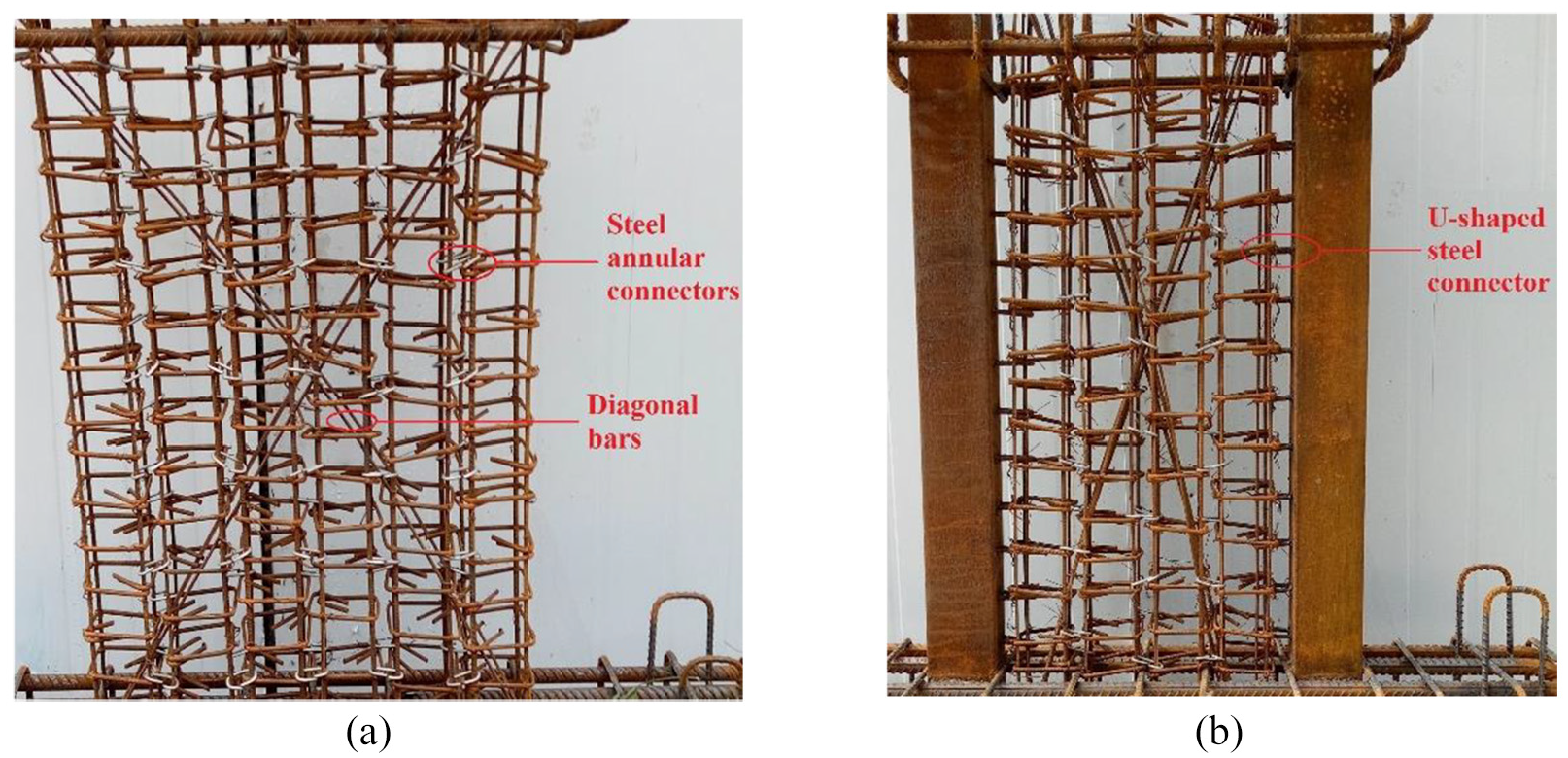
Two different restraining elements: (a) column-type reinforcing element and (b) steel tube and column-type reinforcing elements.
Test setup and loading program
According to the national standard of China (JGJ/T 101-2015, 2015), four shear walls were tested under quasistatic low-cycle cyclic loading using a CSF-500 T loading frame and reaction wall, and the test axial compression ratio was 0.21. The quasistatic test setup is shown in Figure 3. First, a 1000 kN hydraulic jack was used to apply a constant vertical load to the top of the shear wall; then, a horizontal low-cycle repeated load was applied by a 500 kN hydraulic jack. The extensometers were arranged along the middle of the top beam, the ground beam and the three equal parts of the wall body.
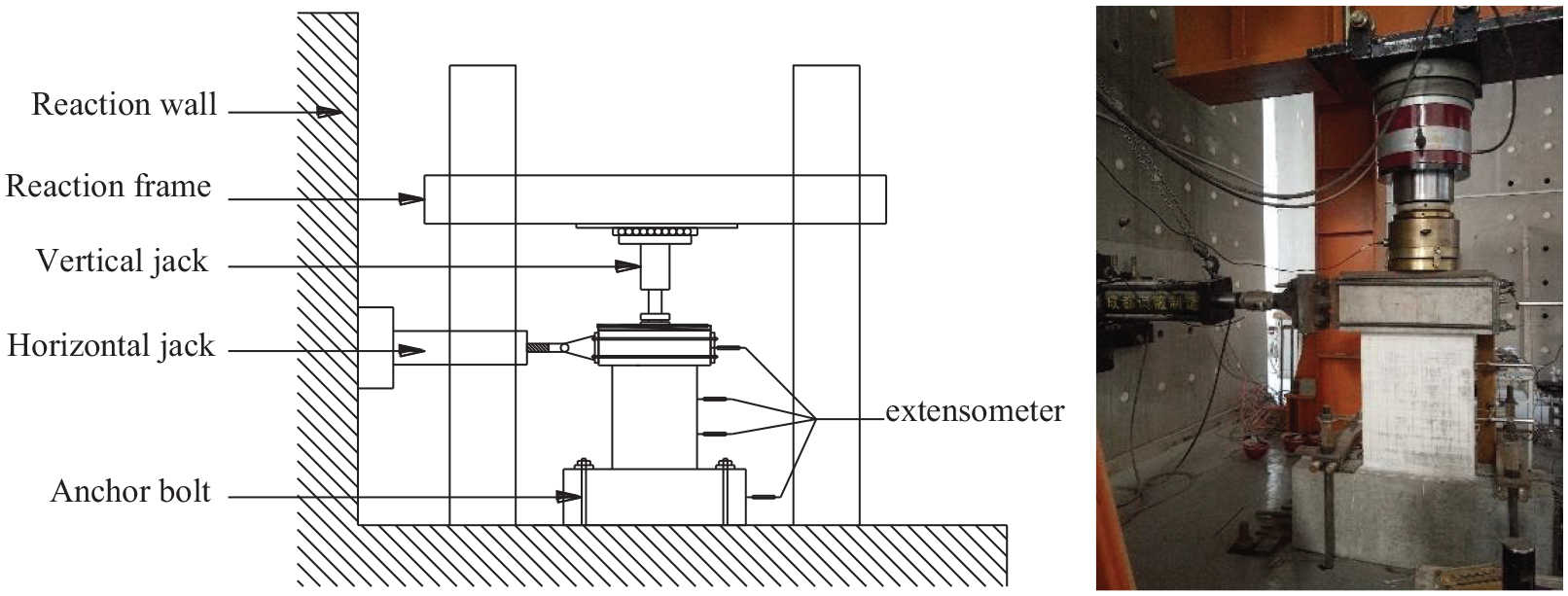
Test setup.
The loading control process is illustrated in Figure 4. Loading and displacement controls were adopted during the low-cycle repeated load process. The load control was adopted before yielding with an integral multiple of 10 kN, and the displacement control was adopted after yielding with an integral multiple of yield displacement Δy. When the horizontal load dropped to 85% of the peak load or when the test specimen was significantly damaged, the loading was terminated.

Loading program.
Experimental results
Damage and failure modes
The failure mode of the RCSW was shown in Figure 5(a). The number of cracks was relatively small, and the cracks were oriented mainly horizontally and were distributed mainly in the lower 1/2 of the wall height. When the wall was destroyed, a large horizontal crack was observed in the root of the wall, which gradually separated from the ground beam, and the concrete on the right side of the wall was crushed and fell off.
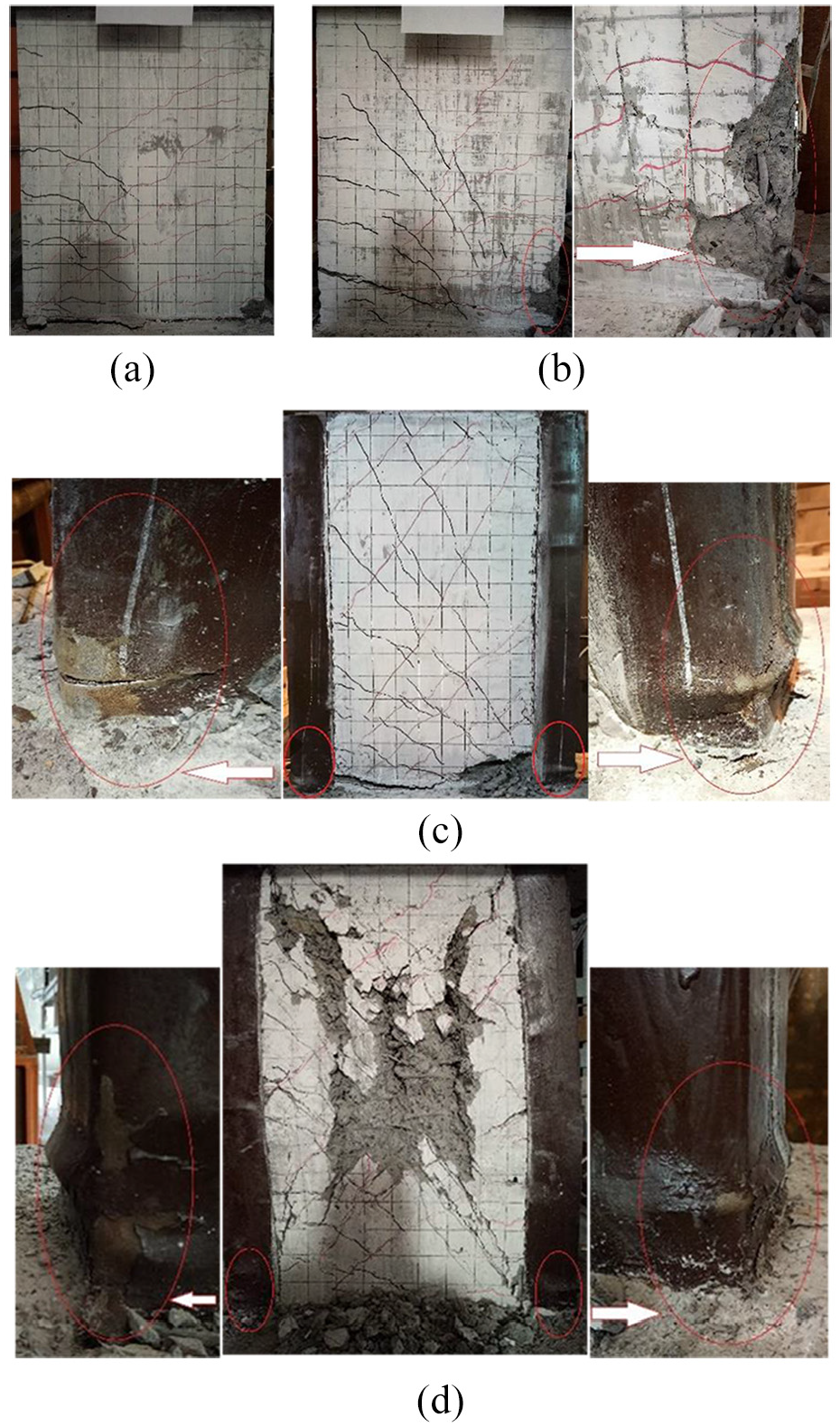
Failure mode of the specimens: (a) RCSW,(b) CTRW, (c) CFST, and (d) CFST-CTRW.
The failure mode of the CTRW was shown in Figure 5(b). Compared with the RCSW, the number of cracks increased. After reaching the peak load, the horizontal cracks gradually became inclined 45 degrees relative to the horizontal. When the specimen was destroyed, an oblique crack inclined at 30 degrees relative to the horizontal was observed at the height of the plastic hinge, splitting the wall. The concrete on the right side of the wall was crushed and fell off, and the main reinforcements of the concealed column buckled and were exposed.
The failure mode of the CFST was shown in Figure 5(c). Compared with the RCSW, there were more cracks, and they were widely distributed over the whole wall; most of the cracks were inclined. During the loading process, first, bending-shear cracks appeared successively within the lowermost 1/3 of the wall and developed obliquely downward from the side to the middle of the wall. During the middle stage of loading, the cracks continued to develop, and the bottom of the steel tube bulged on the sides parallel to the horizontal force. As the repeated loading proceeded, the bulges were repeatedly tensioned and deformed, after which new bulges appeared on the two front faces perpendicular to the horizontal force at the bottom of the steel tube. A horizontal crack appeared at the base of the wall and gradually penetrated and separated from the ground beam. The concrete between the right corner of the wall body and the steel tube was crushed and fell off. The root of the left steel tube was pulled off, and the root of the right steel tube bulged outward. This finding shows that the concrete-filled steel tube element caused a relatively concentrated area of energy dissipation appear at the bottom of the specimen.
The failure mode of the CFST-CTRW is shown in Figure 5(d). Compared with the other three specimens, the number of cracks was the largest, and the distribution of inclined cracks, which appeared throughout the wall, was the densest; in contrast, the main inclined cracks appeared later and developed more slowly than those in the other specimens. These findings provide evidence that the column-type reinforcing element delayed the development of cracks and caused the concrete to fully utilize its energy dissipation capacity during the cracking and closing processes. At the same time, the bulges were repeatedly tensioned and compressively deformed at the bottom of concrete-filled steel tubes with repeated loading, forming a relatively concentrated area of energy dissipation, thereby improving the weakness at the base of the wall and enabling the upper part of the structure to fully consume energy.
Hysteresis curves
The load-displacement hysteresis curves and skeleton curves of the four shear walls obtained from the tests are shown in Figure 6. According to this analysis, the area enclosed by the hysteresis curve and the bearing capacity of the skeleton curve were the largest for the CFST-CTRW, followed by the CFST, the CTRW and the RCSW. The seismic performance and bearing capacity of the specimens were significantly improved by the two different restraining elements. Compared with the hysteresis curve of the CTRW specimen, the hysteresis curve of the CFST specimen was larger and consequently had a larger enclosure area; the hysteresis curve of the CTRW specimen was not plump and exhibited a pinching phenomenon. This finding shows that concrete-filled steel tubes element could effectively improve the bearing capacity and seismic performance of specimens compared with column-type reinforcing elements because the concrete-filled steel tubes element confined the core concrete more effectively than did the column-type reinforcement elements.
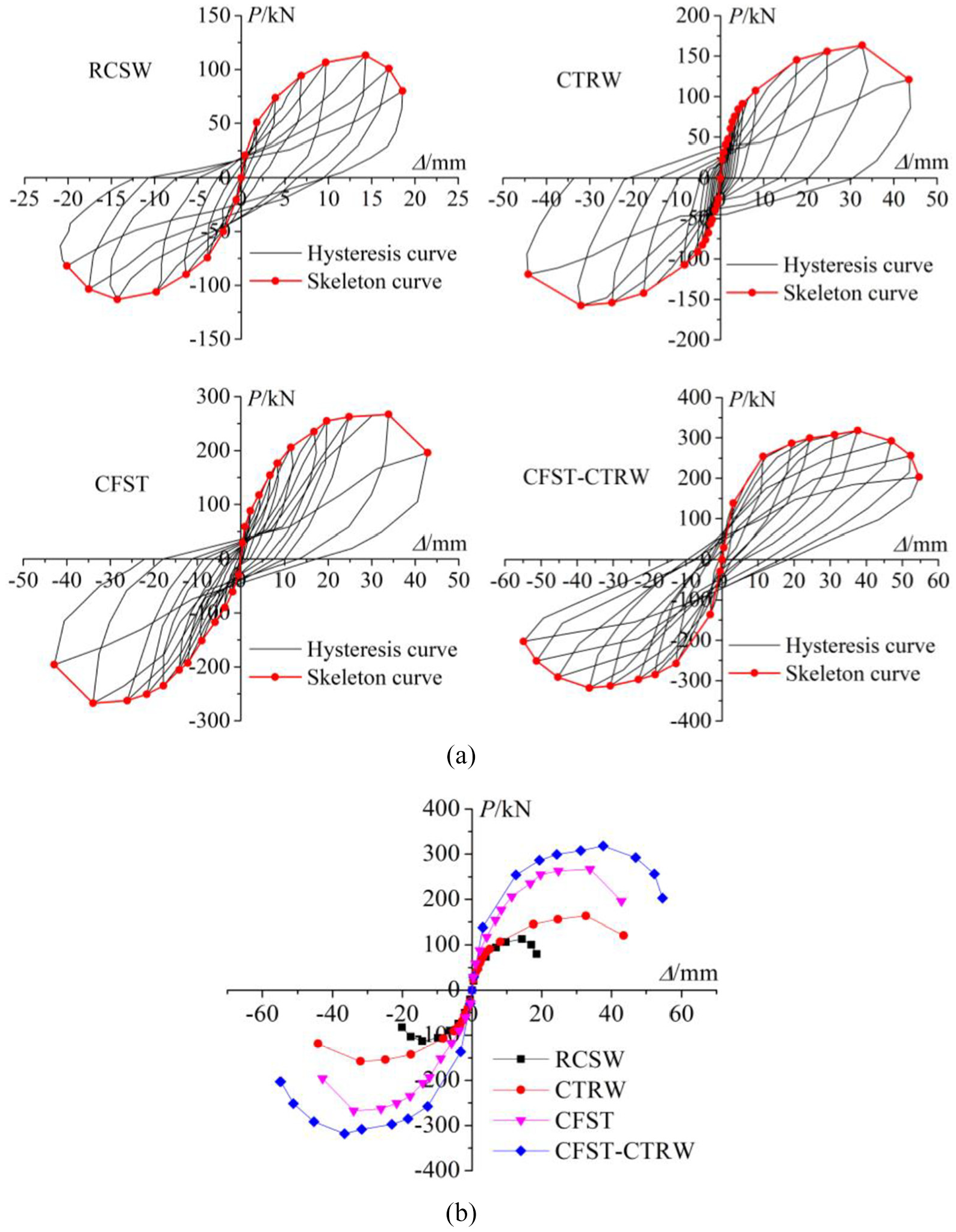
Hysteresis curves and skeleton curves of the specimens: (a) hysteresis curves and (b) skeleton curves.
Stiffness and residual deformation
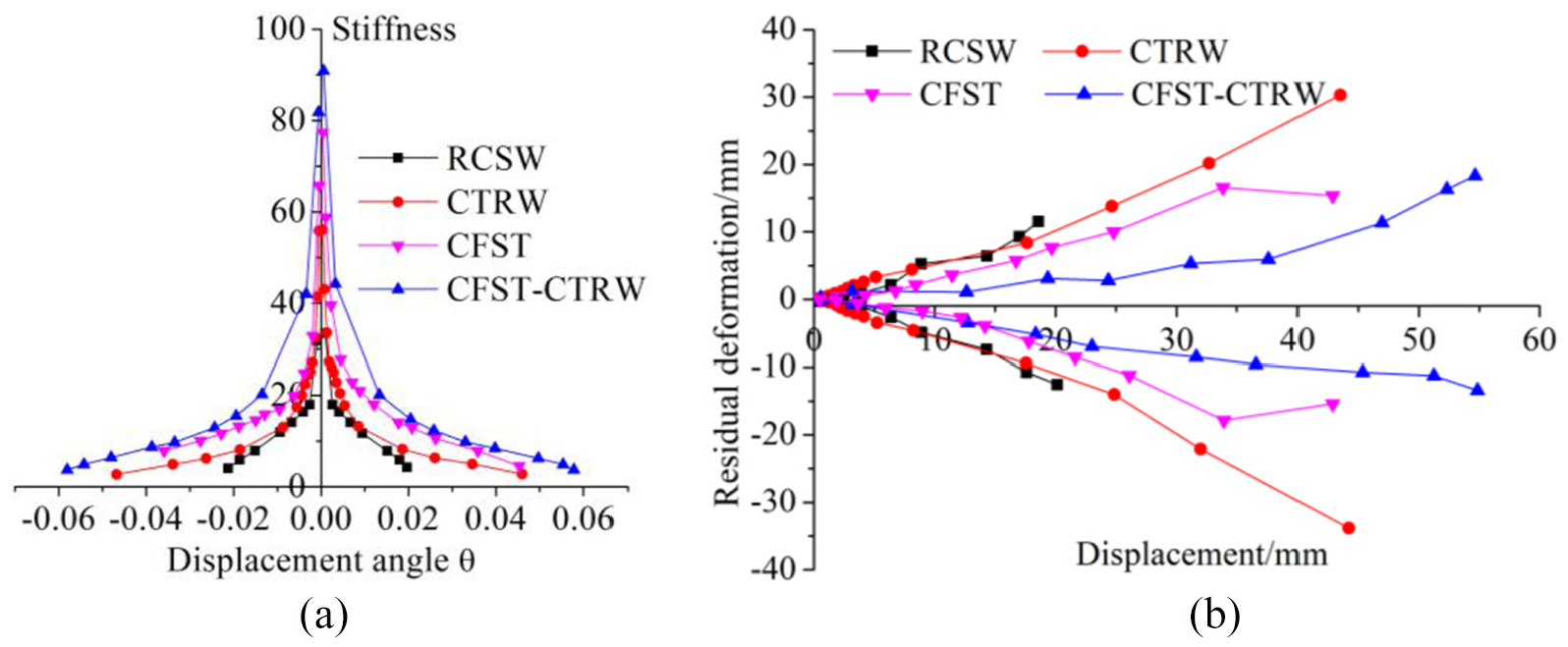
The degradation law of secant stiffness with displacement angle is shown in Figure 7(a). It can be seen that the stiffness of the four specimens decreased exponentially with the increase of displacement angle, and under the same displacement angle, the relationship of stiffness was CFST-CTRW > CFST > CTRW > RCSW. The results show that the two restraining types of the concrete-filled steel tube element and column-type reinforcement element improved the stiffness of the specimens, but the former was more effective than the latter.
Stiffness and residual deformation: (a) stiffness and (b) residual deformation.
In the process of loading, the shear wall will produce certain deformation, which cannot be completely restored to the original state after unloading. At this time, the unrecoverable plastic deformation is the residual deformation, which is shown as the intersection of unloading curve and X-axis on the hysteretic curve. The change law of residual deformation with displacement is shown in Figure 7(b). It can be seen that the residual deformation of all specimens increased linearly with the increase of displacement. Under the same displacement, the relationship of residual deformation was CFST-CTRW < CFST < CTRW < RCSW. The results show that both the concrete-filled steel tube element and column-type reinforcement element reduced the residual deformation of the specimens, and the former was more effective than the latter.
Restraint mechanism analyses
Restraint mechanisms of the two elements
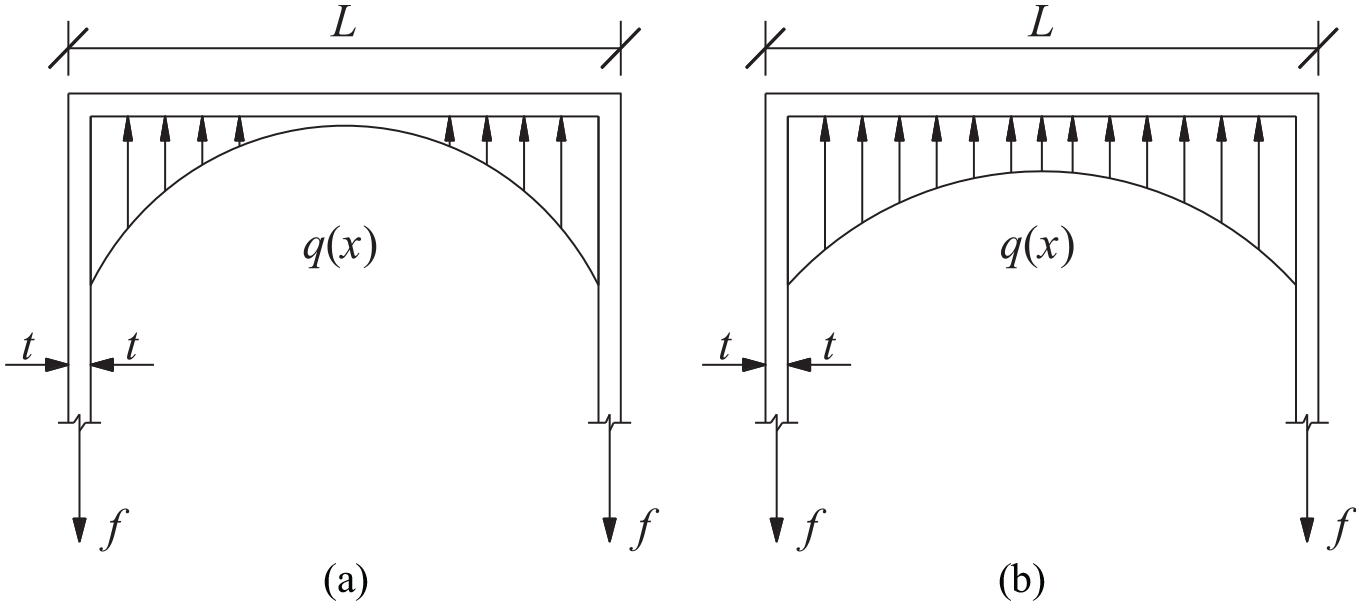
The lateral pressure of the rectangular steel tube on the confined concrete is shown in Figure 8(a), where L is the side length of the rectangular section, t is the thickness of the steel tube or the diameter of the stirrup, and f is the lateral resultant force on the side of the steel tube when the corner yields. The restraint mechanism of the rectangular steel tube-confined concrete was complex, and its failure was caused mainly by the corner of the steel tube yielding and by the longitudinal buckling of the steel plate in the middle. The normal restraining force followed a quadratic distribution along the edge length (Mander et al., 1988; Varma et al., 2005), and the expression for the force is as follows,

where x is the distance between the stress point and the midpoint on each side of the steel tube section, q is the maximum lateral pressure, q = 2tfy / L, and fy is the yield stress of steel.
Lateral pressure of the rectangular steel tube and stirrup: (a) rectangular steel tube and (b) stirrup.
Assuming that the lateral pressure on the confined concrete was evenly distributed along the surface of the concrete in the core area (Mander et al., 1988), the average stress could be calculated according to the average value of the radial restraining force. The formula for calculating the lateral pressure is as follows

Column-type reinforced concrete is essentially stirrup-constrained concrete, the restraint mechanism of which is similar to that of square steel-constrained concrete. The difference is that when the concrete reached the ultimate compressive stress, the midpoint of each side of the stirrup could still provide a greater lateral restraining force. The stirrups were subjected mainly to the vertical and lateral pressures of the concrete, and the failure of the stirrups was attributed primarily to the yielding of the stirrups at the corners, while the middle points of each side of the stirrups did not yield. The stirrup is equivalent to a square steel tube with the same volume, and the lateral pressure of the stirrup on confined concrete is shown in Figure 8(b). The volume stirrup ratio could be expressed as ρv = 4tL / L2 = 4t / L, and the formula for calculating the lateral pressure of the stirrup is as follows

Constitutive relationship between confined concrete and steel
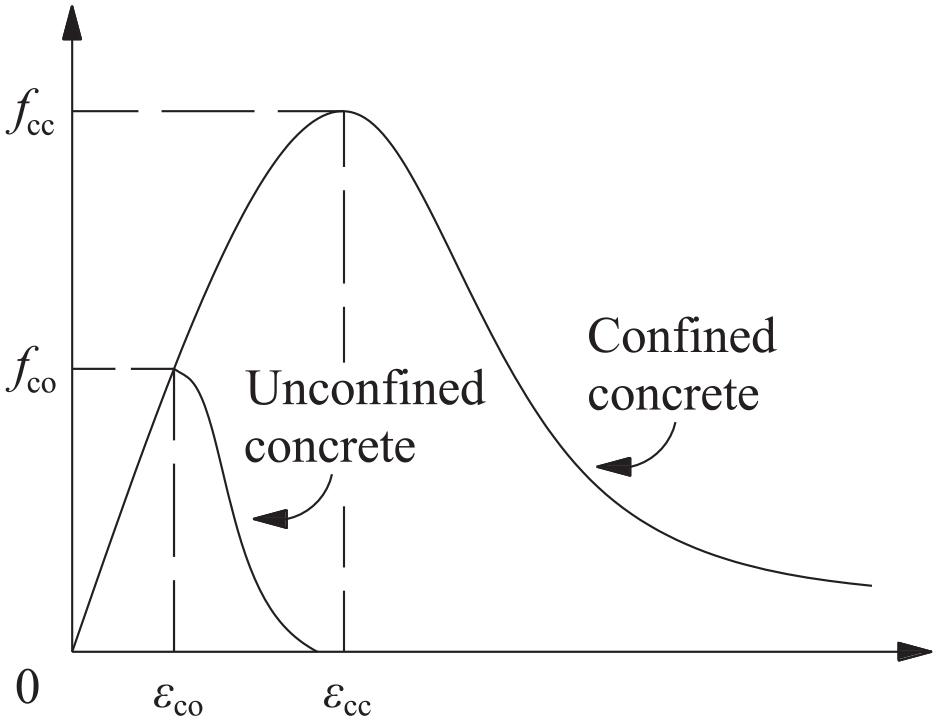
According to the constitutive relationship of confined concrete under a uniaxial load proposed by Mander et al. (1988), as shown in Figure 9, the expressions for the constitutive relationship of confined concrete with a rectangular steel tube and a stirrup are as follows


where fco and εco are the axial compressive strength and corresponding strain, respectively, of unconstrained concrete; fcc and εcc are the axial compressive strength and corresponding strain, respectively, of confined concrete; and fl is the equivalent lateral restraint stress between the rectangular steel tube and stirrup.
Strain–stress relationships of confined concrete.
The steel bar with a grade of HRB400 according to the national standard of China (GB 50010-2010, 2010) that was used in the shear wall specimens in this article displayed an obvious yield platform. The ideal elastic-plastic model was used for the stress–strain relationship of the steel, as shown in Figure 10.

where fy and εy are the yield stress and corresponding strain of steel, respectively; Es is the elastic modulus of steel; and εsu is the ultimate strain of steel.

Constitutive model of steel.
Calculation of the bearing capacity of the normal section
During the test, each shear wall was subjected to the combined action of the axial force N and the bending moment M. The calculation of the normal-section bearing capacity of the shear wall could be carried out according to the method for calculating the eccentric compression composite (Park et al., 2007; Zhang et al., 2009).
Determining the characteristic points on the skeleton curve
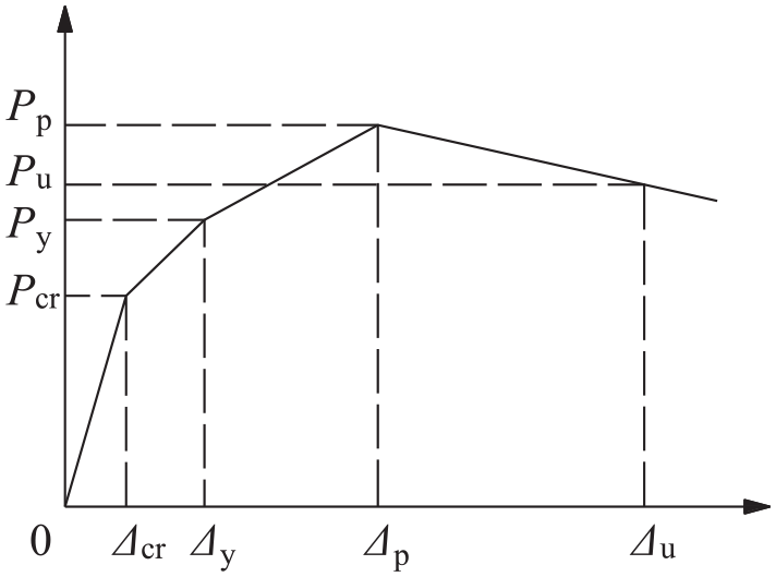
According to the hysteresis characteristics and skeleton curves observed in the tests, the skeleton curves of the four shear wall specimens could be simplified into a four-fold model, as shown in Figure 11. The four feature points were determined as follows: the value of cracking load Pcr was the horizontal load when the first crack appeared in the wall, the peak load value Pm was determined by the highest point on the skeleton curve, the ultimate load value Pu was 85% of the peak load, and the yield load was determined by the energy equivalent method (Ma, 2012).
Model of the skeleton curve.
The principle of the energy equivalent method is shown in Figure 12. When the area of OABO was equal to that of BYNB, point C represented the yield point. The formula for calculating the yield displacement is as follows

where Δy is the yield displacement, Pp is the peak load, Δp is the peak displacement corresponding to the peak load, and Py is the yield load.
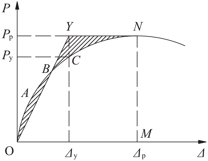
Determination of the yield point.
Cracking load
During the initial stage of loading, the load and deformation through the section of the specimen were both very small, and the specimen was in an elastic state. When the strain of the concrete at the edge of the tension zone reached the ultimate tensile strain εtu of concrete, the concrete cracked. The deformation of the section at this stage conformed to the plane-section assumption, and the specimen displayed the following basic characteristics (Dang et al., 2015). (1) The concrete in the tension zone experienced plastic deformation with a linear stress distribution. (2) The concrete in the compression zone experienced elastic deformation with a linear stress distribution. (3) The compressive strain εc of the concrete at the edge of the compression zone was less than εco, and the stress–strain curves of the confined concrete and the unconfined concrete coincided at this time, as shown in Figure 9. Therefore, the restraining effects of the stirrups or steel tubes were not considered during this stage. The distributions of the stress and strain through the shear wall sections are shown in Figure 13.
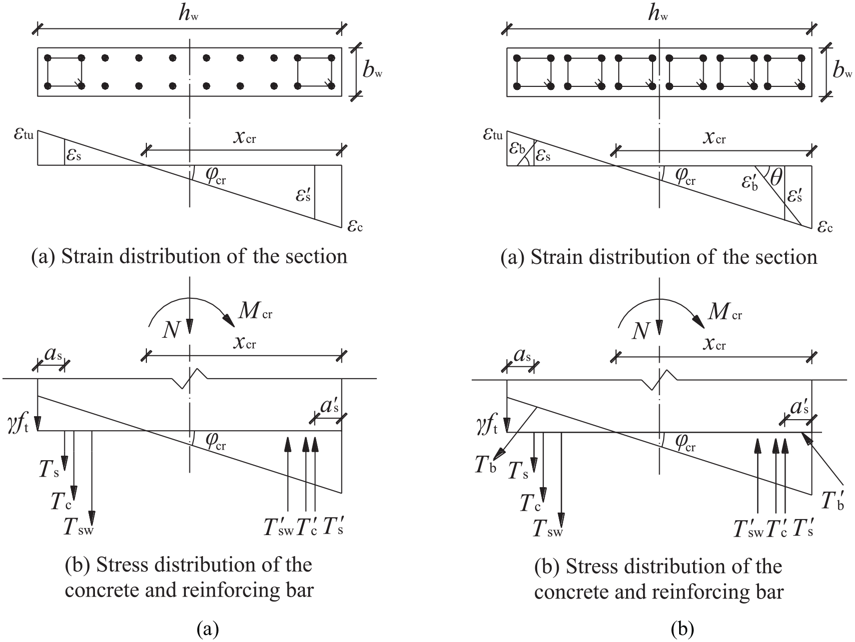
Distributions of the stress and strain in the cracking state: (a) RCSW and (b) CTRW.
According to the plane-section assumption, the curvature of cracks in the section could be obtained by formula (8)

According to the balance of forces through the cross sections, formula (9) could be obtained

where
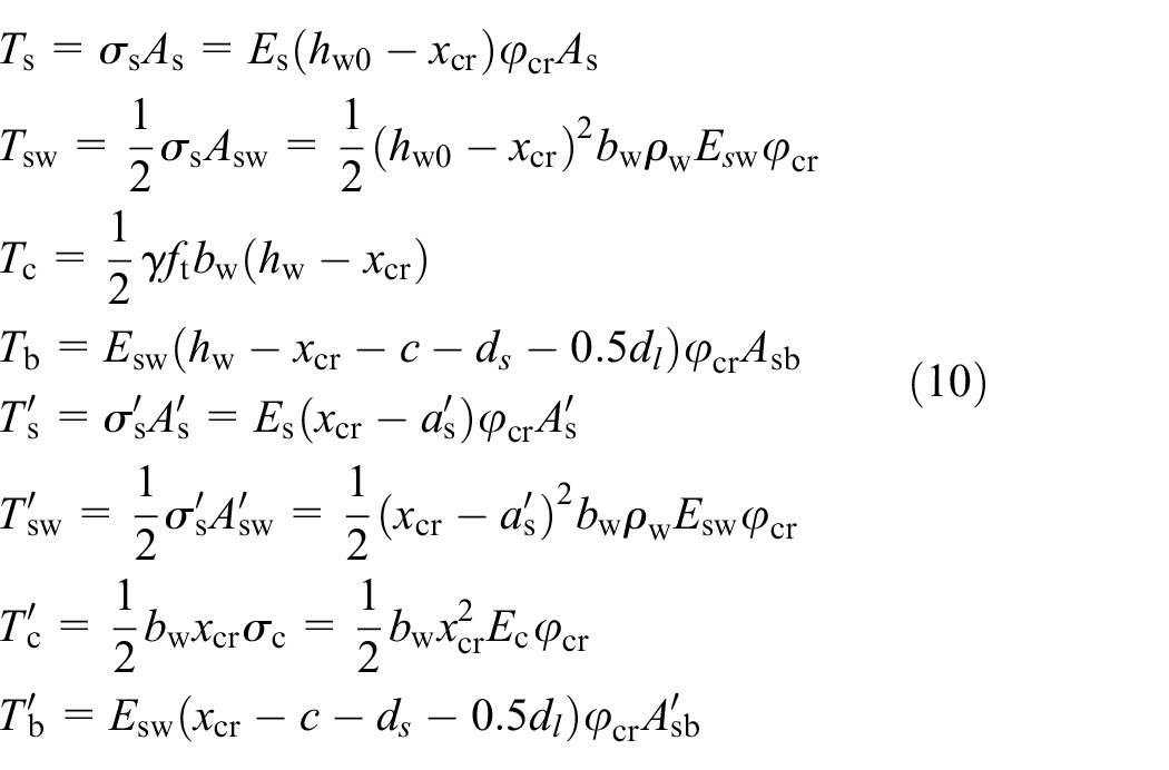
where hw and hw0 are the height and effective height of the section, respectively; hw0 = hw−as; bw is the width of the section; xcr is the height of the compression zone at the cracking state; N is the axial force applied to the specimen, Ts and T′s are the resultant forces of the longitudinal reinforcements at the boundaries under tension and compression, respectively; Tsw and T′sw are the resultant forces of the longitudinal reinforcements in the wall under tension and compression, respectively; Tc and T′c are the resultant forces of concrete in the tension and compression zones, respectively; Tb and T′b are the combined forces of the diagonal bars under tension and compression, respectively; θ is the angle between the diagonal bars and horizontal plane; σs and σ′s are the stresses of the longitudinal reinforcement at the boundaries under tension and compression, respectively; Es is the elastic modulus of the longitudinal reinforcement at the boundary; As and A′s are the cross-sectional areas of the longitudinal reinforcements of the boundaries under tension and compression, respectively; ρw is the reinforcement ratio of the wall; Esw is the elastic modulus of the reinforcement in the wall body; ft is the axial tensile strength of concrete; γ is the plastic influence coefficient of the rectangular cross-section resistance moment with a value of 1.55; c is the thickness of the concrete cover; ds is the stirrup diameter; dl is the longitudinal reinforcement diameter; Asb and A′sb are the cross-sectional areas of the diagonal bars under tension and compression, respectively; and as and a′s are the distances from the joint point of the longitudinal reinforcement at the boundary or steel tube to the outer edge of the tension or compression zone, respectively.
The height value xcr and curvature value φcr of the compression zone of each shear wall section in the cracking state could be obtained by employing formulas (8), (9), and (10) simultaneously.
All the forces on the section took the moment on the centroid axis of the section, and the moment of the shear wall section in the cracking state could be obtained by using formula (11)
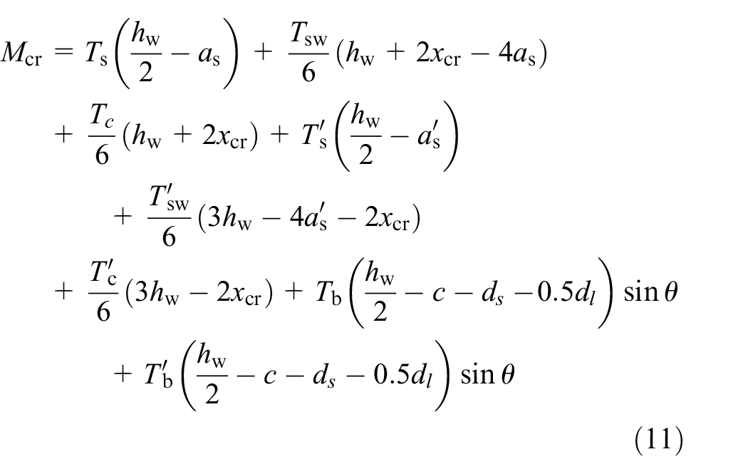
The formula for calculating the crack load Pcr is as follows

where H is the height of the shear wall.
Yield load
When the strain of the steel tube or longitudinal steel bar in the tension zone of the shear wall section reached the yield strain εy of steel, the specimens reached the yield stage. The deformation of the section during this stage conformed to the plane-section assumption, and the specimens displayed the following basic characteristics: (1) the tensile stress of concrete in the tension zone was negligible and (2) the concrete in the compression zone experienced elastic deformation with a linear stress distribution. The compressive strain εc of the concrete at the edge of the compression zone was less than εco, and the restraining effects of the stirrups or steel tubes were not considered. The distributions of the stress and strain through the shear wall sections are shown in Figure 14.

Distributions of stress and strain in the yield state: (a) RCSW, (b) CTRW, (c) CFST, and (d) CFST-CTRW.
According to the plane-section assumption, the yield curvature of the section could be obtained by formula (13)

According to the balance of forces through the cross sections, formula (14) could be obtained

where
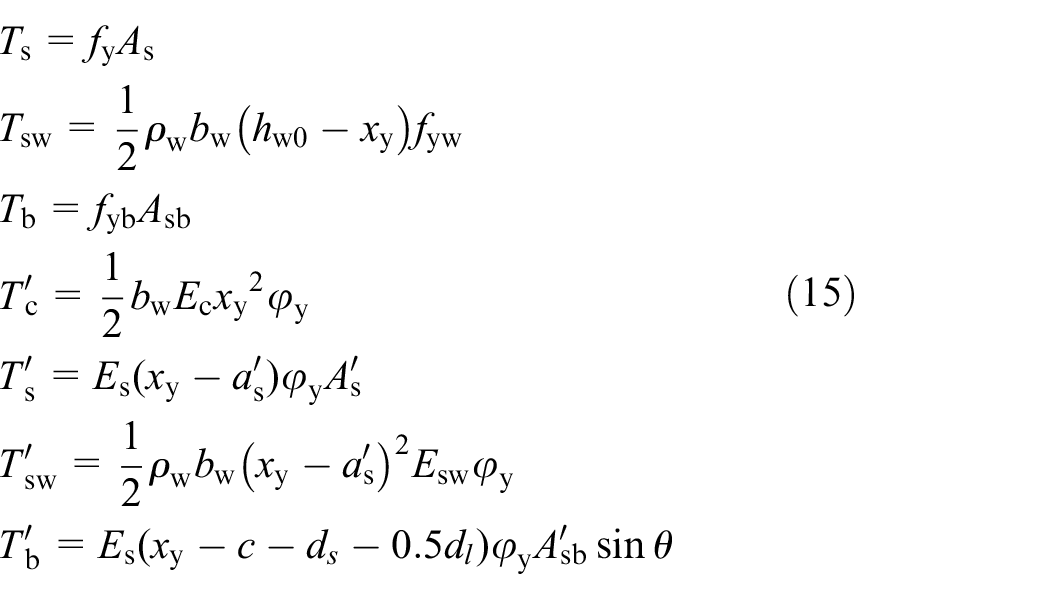
where fy is the yield strength of the steel tube or steel bar at the boundary; fyw is the yield strength of the steel bar in the wall body; fyb is the yield strength of the diagonal steel bar; Asb and A′sb are the cross-sectional areas of the diagonal bars under tension and compression, respectively; and xy is the height of the compression zone at the yield state. The height xy and curvature φy of the compression zone in the yield state could be obtained by solving the formulas shown above simultaneously.
All the forces on the section took the moment on the centroid axis of the section, and the moment of the shear wall section in the yield state could be obtained by calculating formula (16)
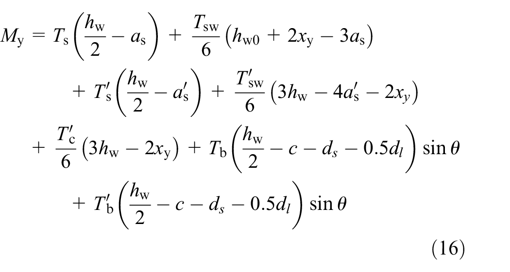
The formula for calculating the yield load Py is as follows

Peak load
For steel tube-confined or stirrup-confined concrete shear walls, when the compressive strain of the confined concrete at the edge of the compression zone reached the peak compressive strain εcc of the confined concrete, the specimens reached the maximum bearing capacity; the basic characteristics were as follows. (1) The tensile stress of the concrete in the tension zone was negligible. (2) The actual compressive stress of the concrete was equivalent to the rectangular stress, and the height x of the equivalent rectangular stress was 0.8 times the height xn of the actual compression zone. (3) It was assumed that the stress of steel bars or steel tubes in the ends of tension and compression area were all reached yield, and all the longitudinal reinforcements in tension area yield outside the range of 1.5 times of compression area (JGJ3-2010, 2010). The distributions of stress and strain at the peak point are shown in Figure 15.
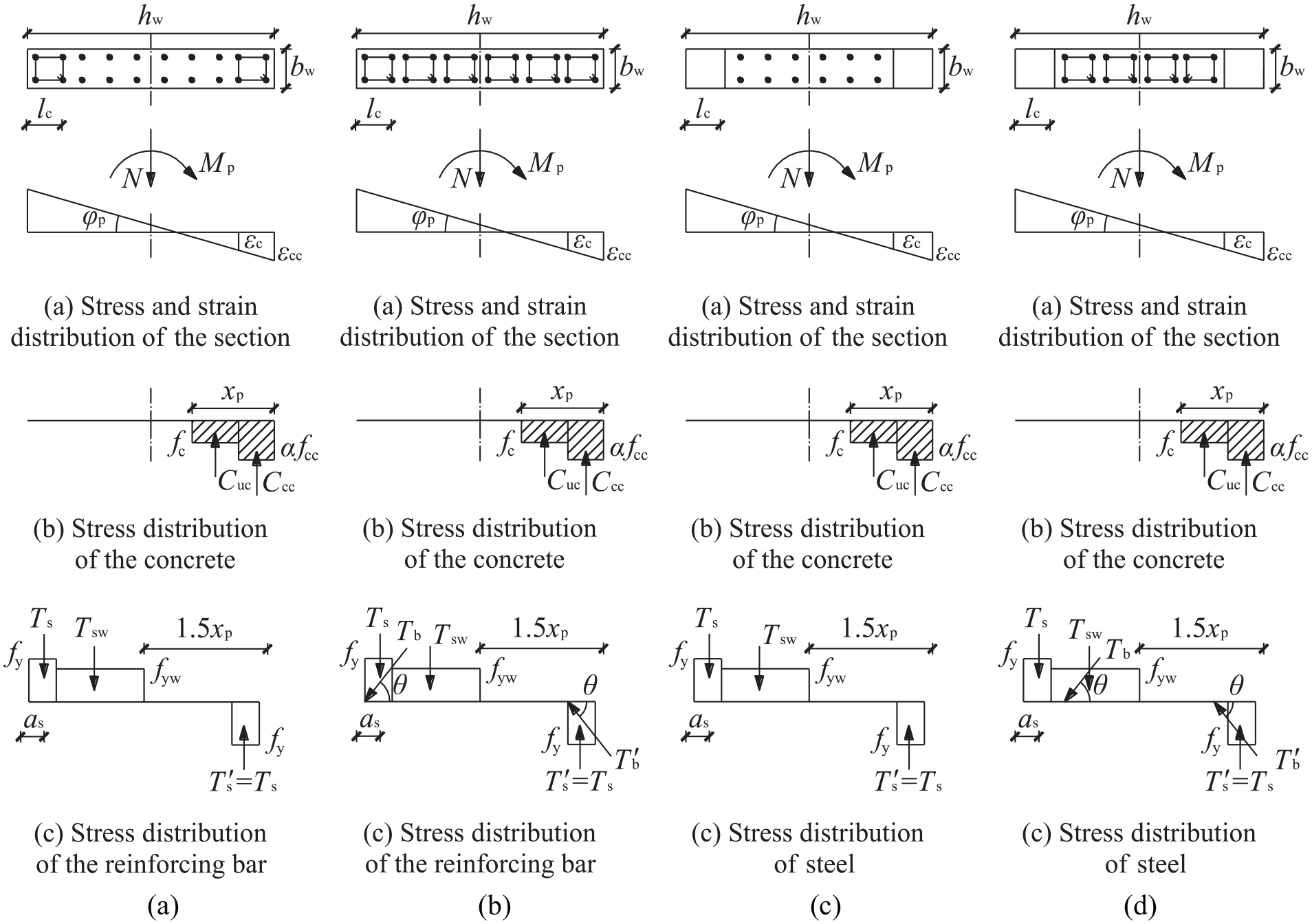
Distributions of stress and strain at the peak point: (a) RCSW, (b) CTRW, (c) CFST, and (d) CFST-CTRW.
The peak curvature φy of the specimens at the peak point could be calculated using formula (18)

where ξ is the relative height of the compression zone and εcc is the peak compression strain of confined concrete.
According to the balance of forces through the section, the following relationships could be obtained

where

When xp > lc

where Ccc is the pressure of confined concrete, α is the coefficient related to the length of the confined zone with a value of 0.8 in this article, Ccu is the pressure of unconstrained concrete, and xp is the height of the compression zone at the peak point.
The height xp and curvature φp of the compression zone at the peak point could be obtained by solving the formulas shown above simultaneously. All the forces on the section took the moment on the centroid axis of the section, and the moment of the shear wall section at the peak point could be obtained by calculating formula (22)
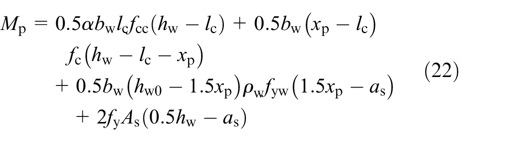
When xp < lc

The moment of the shear wall section at the peak point could be obtained by calculating formula (24)
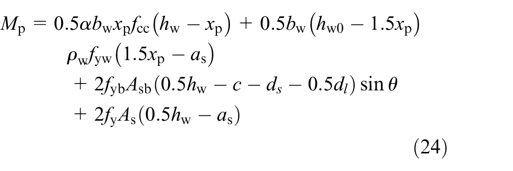
The formula for calculating the peak load Pp is as follows

Ultimate load
When the load decreased to 0.85 times the peak load, the specimens reached their ultimate state

Comparisons between the calculated and experimental values
Comparisons between the calculated and experimental values of the bearing capacity of the shear wall specimens through the normal section are shown in Table 3. Evidently, the calculated values were in good agreement with the experimental values overall, demonstrating that the method used to calculate the bearing capacity of the four shear wall specimens proposed in this article was more reasonable. However, the calculated crack load values were larger than the experimental values, which may have been due to the weakness of the wall concrete caused by the use of improper joints within the formwork and to the uneven mixing of concrete during the process of the fabrication of the shear wall specimens, as uneven mixing could lead to early cracking of the wall concrete during the experimental loading process.
Comparisons between the calculated and experimental values (kN).

RCSW: reinforced concrete shear wall; CTRW: column-type reinforced shear wall; CFST: concrete-filled steel tube; CFST-CTRW: concrete-filled steel tube boundary and column-type reinforced wall.
Conclusion
In this article, four shear wall specimens with two different restraining elements were tested under low cyclic loading. The failure modes, hysteresis properties, stiffness and residual deformation of the specimens were analyzed, and the restraint mechanisms of the steel tube and stirrup on the concrete in the core area were studied. On this basis, the bearing capacity of each specimen in each loading stage was calculated. The main conclusions are as follows:
The two restraining elements, namely, the concrete-filled steel tube and column-type reinforcement, significantly improved the bearing capacity of the shear wall specimens. The column-type reinforcing element caused the horizontal cracks in the wall to develop into oblique cracks, forced the concrete to fully utilize its energy dissipation capacity during the cracking and closing processes, and improved the bearing capacity of the specimens.
Concrete-filled steel tube elements could improve the bearing capacity and stiffness and reduced the residual deformation of the specimens more effectively than column-type reinforcing elements, because the former confined the core concrete more effectively than the latter. Bulges were repeatedly tensioned and compressively deformed at the bottom of the concrete-filled steel tubes with repeated loading, forming a relatively concentrated area of energy dissipation, thereby improving the weakness of the base of the wall and enabling the upper part of the specimen to fully consume energy.
The calculated load values of the four shear wall specimens were in good agreement with the experimental values, demonstrating that the methods proposed in this article that were used to calculate the equivalent lateral pressures of the two restraining elements and the bearing capacity in each stage considering the equivalent lateral pressure were reasonable.
Footnotes
Declaration of Conflicting Interests
The author(s) declared no potential conflicts of interest with respect to the research, authorship, and/or publication of this article.
Funding
The author(s) disclosed receipt of the following financial support for the research, authorship, and/or publication of this article: This work was sponsored by the National Natural Science Foundation of China (No. 51868059), the Natural Science Foundation of the Inner Mongolia Autonomous Region (IMAR) (No. 2016BS0504), and the Scientific Research Projects in Institutions of Higher Learning of IMAR (No. NJZC16091).
