



Abstract
A lap-spliced crosstie comprises two J-shaped rebars, each with a 180° hook at one end and straight at the other end. Six large reinforced concrete columns subjected to lateral cyclic loading were tested. The results indicated the following: (1) the confining effect of horizontally lap-spliced crossties is similar to that of vertically lap-spliced crossties. (2) Splice length of the lap-spliced crossties that is smaller than the code requirement can also provide sufficient concrete confinement. (3) A method for determining required lap splice length for lap-spliced crossties is proposed. (4) The lap-spliced crosstie can considerably improve the constructability of the crossties. Furthermore, the construction quality of reinforced concrete column reinforcement and the seismic resistance capability of reinforced concrete structures can be significantly upgraded.
Introduction
The transverse reinforcement of a seismic reinforced concrete (RC) column generally comprises an outer hoop and several crossties. For the convenience in construction, conventional crossties with a 90° hook at one end and 135° hook at the other end are employed. The poor performance of 90° hook has been evident, leading to rapid loss of gravity load resistance. Some special crossties have been introduced to solve this problem and summarized in Lee et al. (2012, 2014). Their behaviors are not reviewed here.
As illustrated in Figure 1, a lap-spliced crosstie is composed of two J-shaped rebars, each of which has a 180° hook at one end and is straight at the other end. Lap-spliced crossties can be inserted into a column from the opposite side of the column, which can be achieved if the clear spacing among the longitudinal reinforcements meets the design code requirement, providing adequate space for the assembly. The lap-spliced crosstie is innovative and can considerably improve the constructability of the crossties, especially when construction space is insufficient.

Schematics of a lap-spliced crosstie: (a) decomposition of lap-spliced crosstie, (b) vertically lap-spliced crosstie, and (c) horizontally lap-spliced crosstie.
Lee et al. (2012, 2018) and Lee and Chen (2020) conducted axial loading and flexural tests on large RC columns. The following results were obtained: (1) the confining effect of lap-spliced crossties was superior to that of conventional crossties and comparable to that of one-piece crossties with a 180° hook on both ends (abbreviated 180/180 crossties hereafter) regardless of whether the magnitude of the axial load was 0,
Experimental design
Design and manufacture of specimens
Six large RC specimens, including columns and foundations, were manufactured in this study. The column cross-sectional area, column length, longitudinal reinforcement configuration, and number of longitudinal and transverse reinforcement of the six specimens were identical. The only differences between the specimens were the crosstie type, material strength, and lap splice length. The specimen number, crosstie type, nominal strength of the crosstie, lap splice length, and confining force are presented in Table 1.
Crosstie type, lap splice length, measured concrete compressive strength, and confining force of specimens.

Ratio of confining force equal to the ratio of actual confining force to required confining force.
The specimens had cross-sectional length and width of 470 mm, and 12 D25 longitudinal reinforcements were employed, as illustrated in Figure 2. The ratio of longitudinal reinforcement was 2.8%. Concrete with a nominal compressive strength

Cross section of Specimen C.
For all of the specimens, the inside bend diameter of the hoops and crossties was 40 mm. The length of the straight extension of the hoops or crosstie hooks was 80 mm. Conventional crossties (referred to as 90/135 crossties) were adopted in Specimen C as illustrated in Figure 2. As shown in Figure 3, 180/180 crossties were employed in Specimen R. Horizontally lap-spliced crossties were used in Specimens H-280, H-330, and H-360(A and B), and the lap splice length was 280, 330, and 360 mm, respectively. Cross sections of Specimen H-280 and H-360(A and B) are shown in Figures 4 and 5.
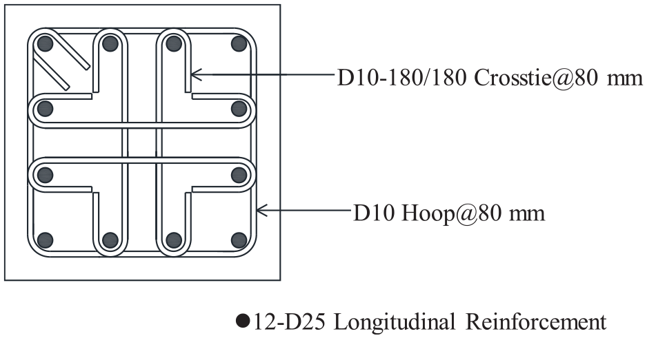
Cross section of Specimen R.
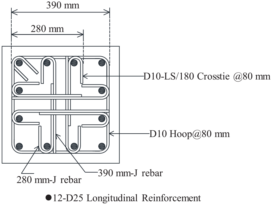
Cross section of Specimen H-280.

Cross section of Specimens H-360A and H-360B.
Two J-shaped rebars were combined through tension lap splicing to form a crosstie. According to the specification in ACI 318M-11, a tension lap splice is categorized as a Class B lap splice and thus requires a lap splice length of

According to the specification for a Class A lap splice, the length of a lap splice must be
The main dimensions and rebar configuration are displayed in Figure 6. The overall length of the column was 2026 mm, the distance (L) from the point of application of lateral load to the foundation was 1600 mm, and the corresponding height–width ratio was 3.4. A 15-mm-thick steel plate was placed on the top and one on the bottom of the column, and all of the longitudinal reinforcements were welded onto the steel plates to make them be placed accurately. A 250 mm round hole is pre-cut in the center of the top steel plate to facilitate concrete placement vertically, as shown in Figure 7. After concrete placement, the 250 mm round steel plate was recapped by non-shrinkage cement mortar with a nominal compressive strength of 56 MPa.
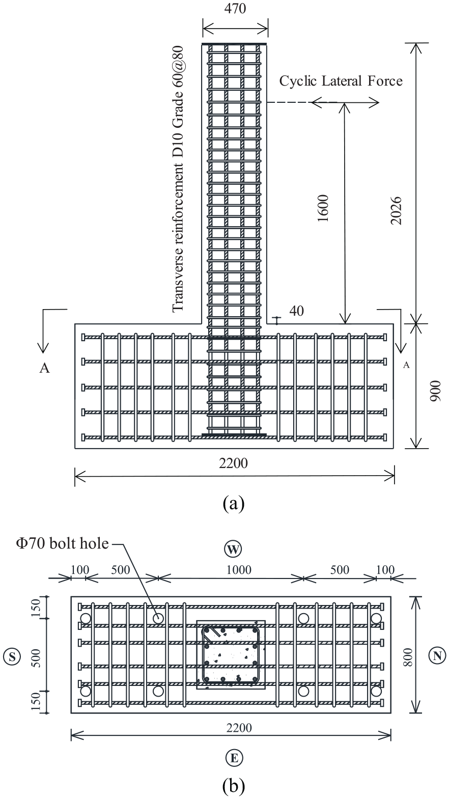
Schematic of specimen size and rebar configuration (unit: mm): (a) elevation drawing and (b) section A-A.
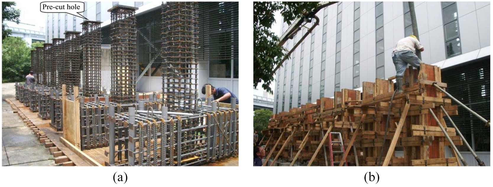
Pre-cut hole of top steel plate and concrete placement process of specimens: (a) a 250 mm round hole is pre-cut in the center of the top steel plate and (b) concrete placement process.
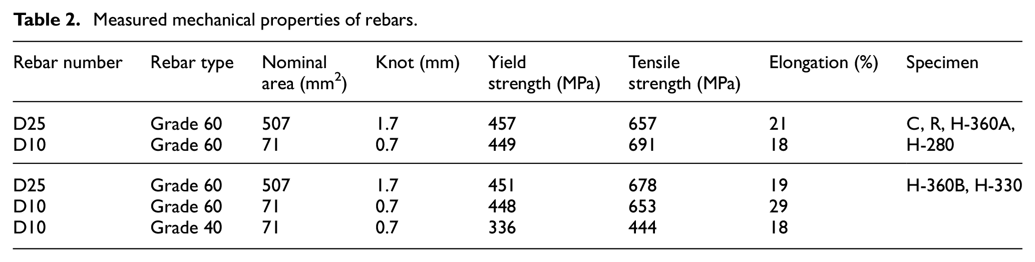
Ready mixed concrete was poured into the upright specimens in two steps. First, concrete was poured up to the upper edge of the foundation; second, it was poured to the bottom of the top steel plate. The average measured compressive strength of each specimen of three cylinder samples is displayed in Table 1, and the average measured mechanical properties of three samples are listed in Table 2. Specimen C, R, H-360A, and H-280 were made and tested in 2014. In order to further clarify the influence of the lap splice length, Specimens H-360B and H-330 were made and tested in 2016. Therefore, the obvious difference of measured concrete compressive strength of specimens in two stages could be found in Table 1. For all RC column specimens that contained lap-spliced crossties, the ratio of the actual confining force (the product of the measured yield strength and gross cross-sectional area of the transverse reinforcement) to the required confining force ranged from 93% to 108%, and the ratio of the lap splice length to the specified lap splice length ranged from 72% to 92%.
Measured mechanical properties of rebars.
Experimental apparatus and loading protocol
Loading tests were conducted in the Large-Scale Structure Testing Laboratory of the Architecture and Building Research Institute, Ministry of Interior. The experimental apparatus is displayed in Figure 8. A specimen to be tested was positioned in the large-scale experimental frame with its foundation screwed to the strong floor. At the beginning of the loading test, 1.86 MN of axial compression load was applied using a 6-MN actuator to the specimen, followed by the application of cyclic lateral load. The axial compression load was applied using force control, and the magnitude was equivalent to
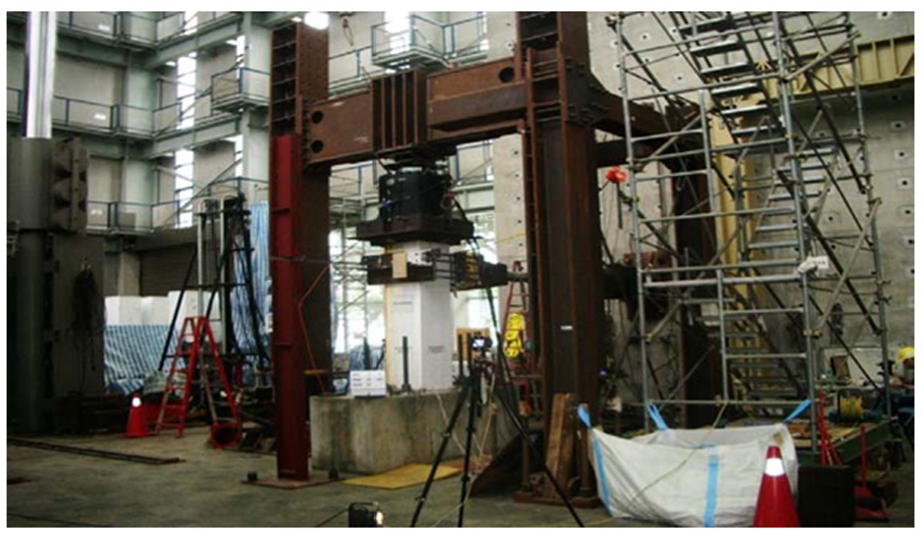
Experimental apparatus.
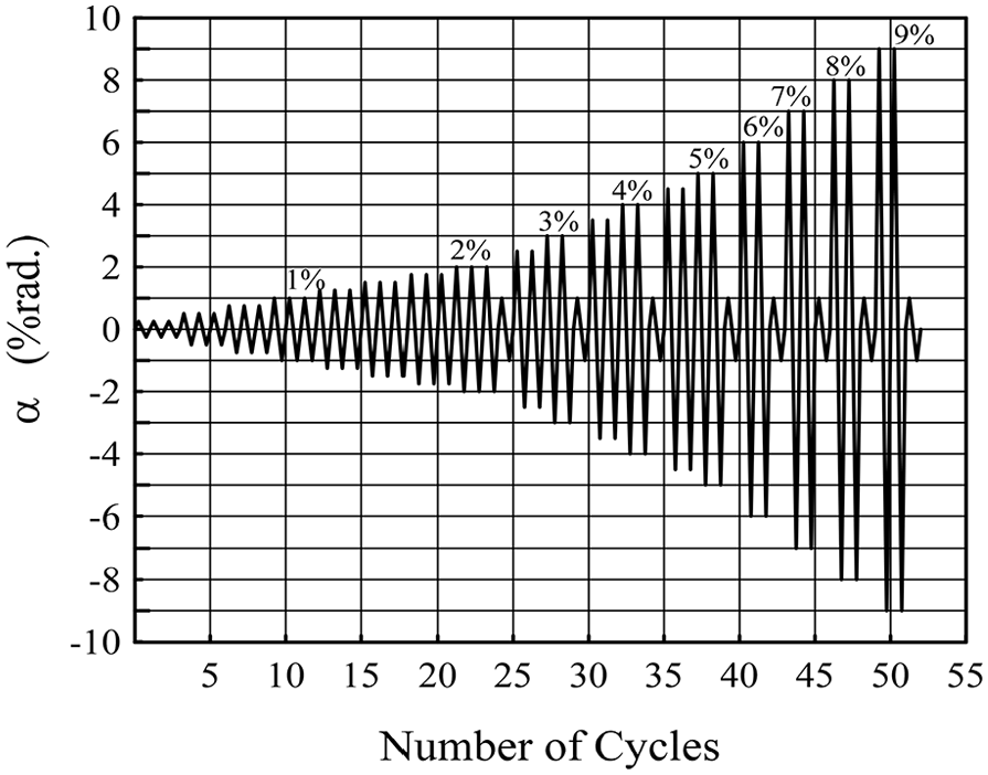
Lateral drift and loading protocol.
The applied load was measured using a built-in differential pressure gauge within the hydraulic actuator. Lateral displacement of the lateral loading point was measured using an external displacement meter. To trace crack formation and development, the sides of the specimens were coated with white paint, and 100 mm × 100 mm squares were outlined in black at 500 mm above the column foundation before testing.
Results
Overall behavior
During the loading test, the greatest displacement of the specimen in each loading cycle was recorded to assess crack development. Cracks caused by loads exerted in the positive and negative directions are indicated in blue and red, respectively. Cracks can be divided into two categories: flexural (horizontal) and flexural shear (inclined). Flexural cracks occurred on the north and south sides of the column specimen, whereas flexural-shear cracks occurred on the east and west sides. Figure 6(b) shows the detailed definitions of the directions. In all specimens, cracks and damage were concentrated at the bottom of the column, and all the dominant damage was flexural failure. Although the specimens displaced to different degrees, the crack kinematics sequence was similar. The crack kinematics sequence of Specimen C, for example, was as follows: when
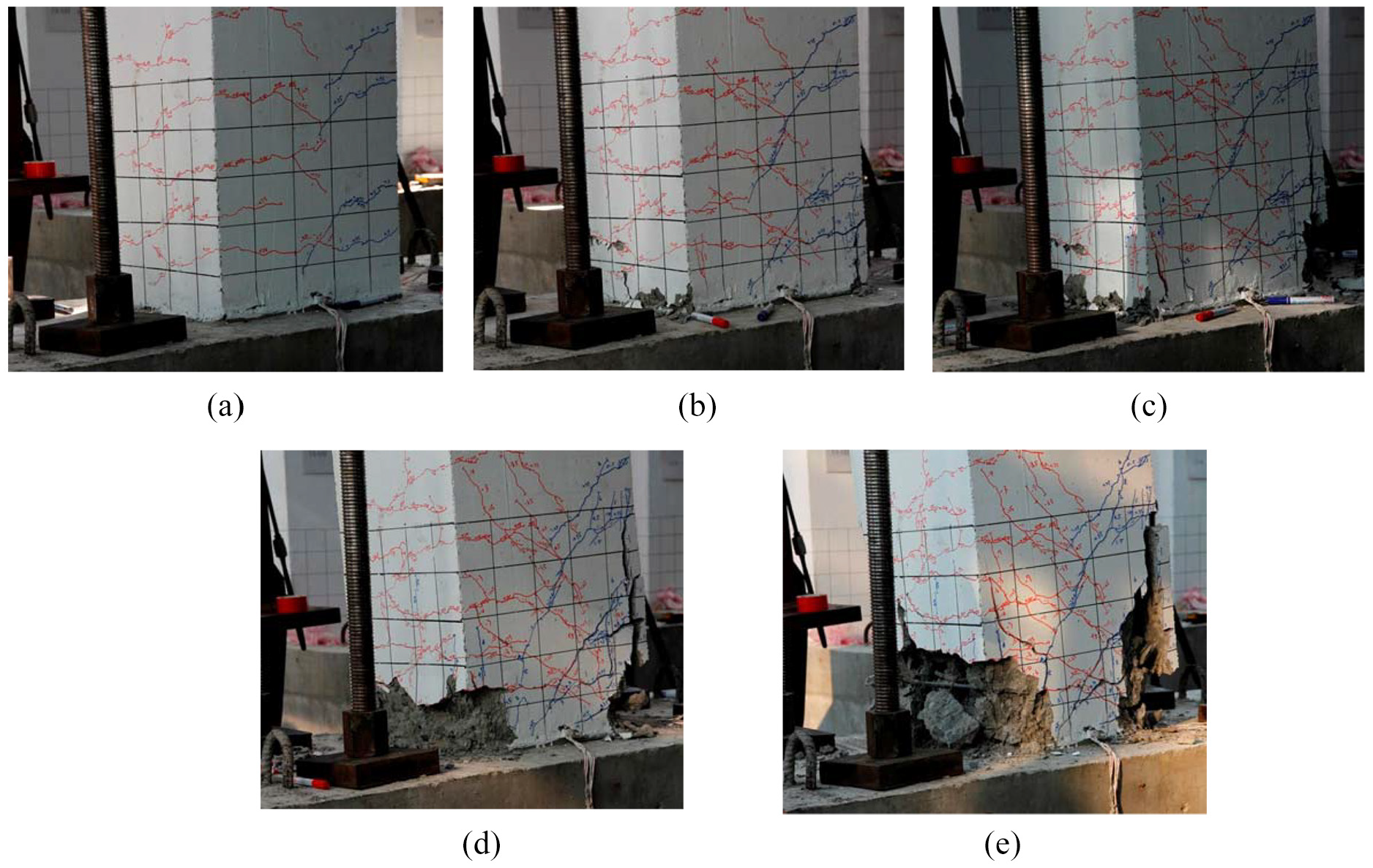
Damage in Specimen C (on west and north sides of the specimen): (a) α = 1%, (b) α = 3%, (c) α = 4%, (d) α = 6%, and (e) α = 8%.
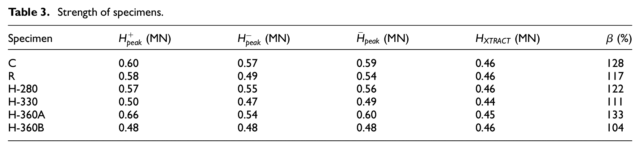
The lateral load–displacement (H-δ) hysteretic loops of all specimens are displayed in Figure 11. The envelope curve of the first loop for each inter-story drift angle is presented in Figure 12. Let the peak load in the positive and negative directions be

Lateral load–displacement hysteretic loop of specimens. (a) Specimen C, (b) Specimen R, (c) Specimen H-360A, (d) Specimen H-280, (e) Specimen H-360B, and (f) Specimen H-330.
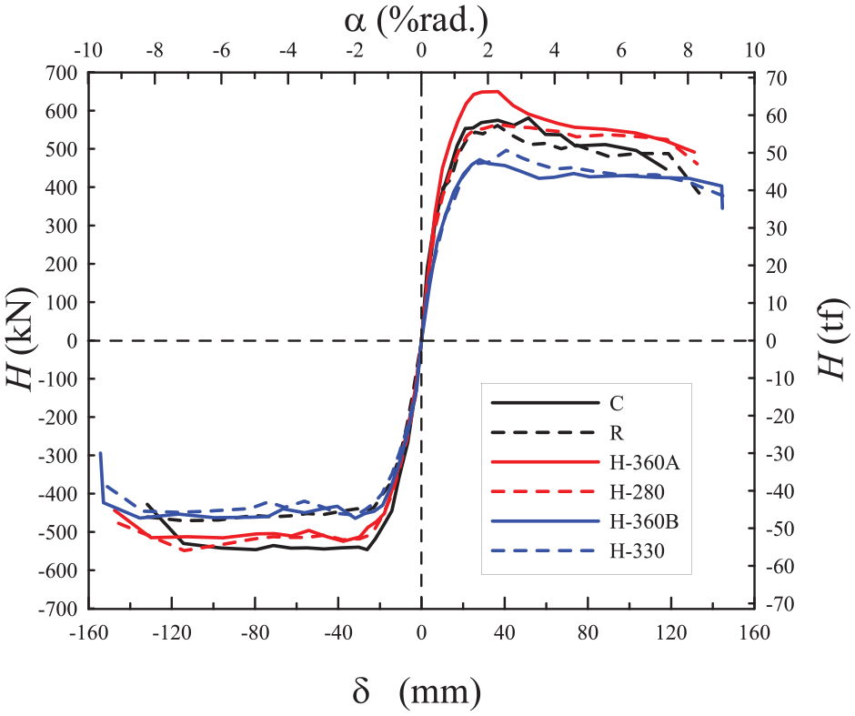
Lateral load–displacement envelope curves.
Strength of specimens.
On the basis of the load–displacement envelope curve and using the envelope curve in the positive direction as an example (Figure 13), the slope of the line connecting the point of origin and the corresponding point to
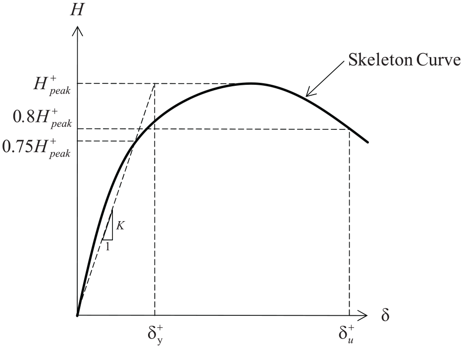
Definitions of lateral yield and ultimate displacement.
Lateral displacements, inter-story drift angle capacity, and plastic rotation capacity.
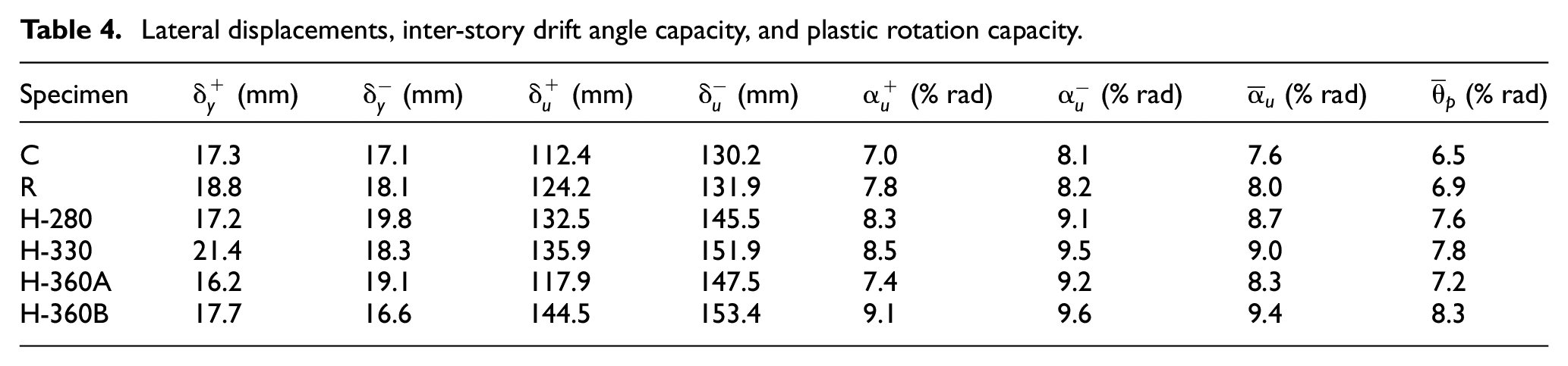
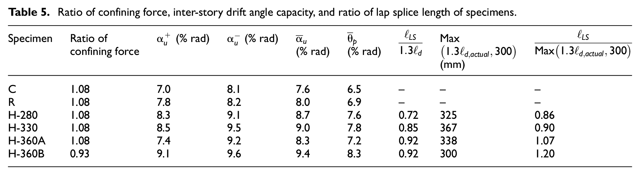
As recommended in ACI 374.1-05 (2005), columns must have an inter-story drift angle of at least 3.5% rad under cyclic lateral load. As revealed in Table 4, the inter-story drift angle capacity
Performance of lap-spliced crossties
As can be seen from Table 4, the
Finally, the
Therefore, it can be concluded that use of horizontally lap-spliced crossties results in higher performance than use of 90/135 crossties, and the performance is comparable to that when 180/180 crossties are employed. Furthermore, the

where
Ratio of confining force, inter-story drift angle capacity, and ratio of lap splice length of specimens.
Figures 14 to 16 present typical photographs of the plastic hinge zone of specimens after the loading test. All of the 90° hooks in the conventional crossties of Specimen C were stretched outward, and some of the 135° hooks were also moderately stretched (Figure 14). The stretching of the 90° hooks was probably the main cause of the specimen’s relatively poor ductility. Concrete inside the 180° hooks of the one-piece crossties in Specimen R was closely attached to the hooks, and negative deformation was not discovered in the hooks (Figure 15). Concrete inside the hooks of the lap-spliced crossties in Specimen H-330 was also closely attached to the hooks (Figure 16), and the straight end of the J-shaped rebars did not drift into the column. This finding suggests that two J-shaped rebars can be effectively combined to form a crosstie with a 180° hook on both ends.
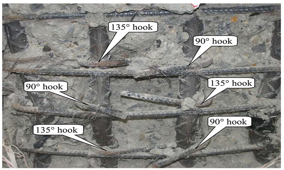
Appearance of the plastic hinge zone of Specimen C.
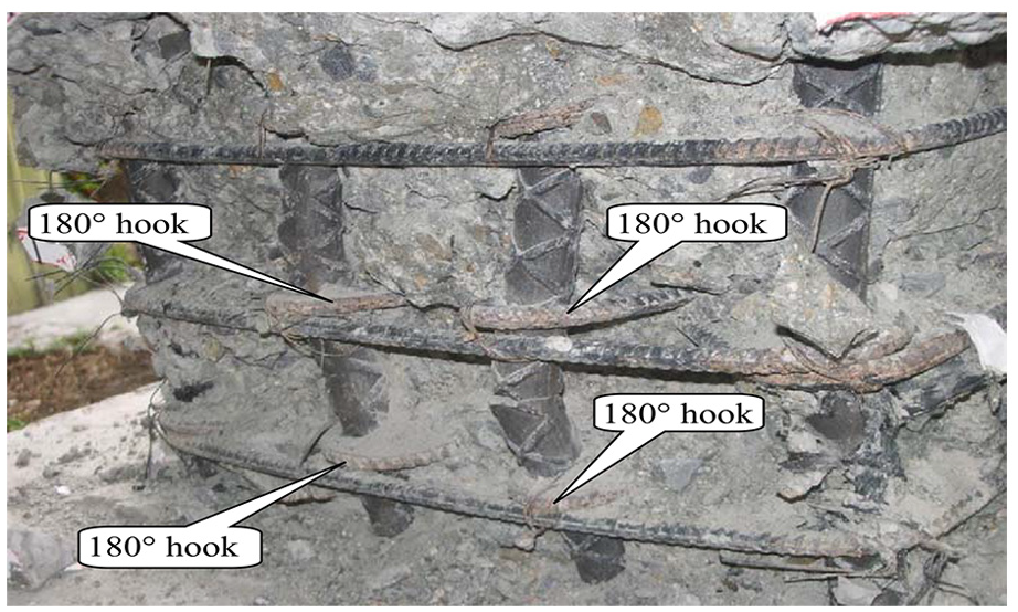
Appearance of the plastic hinge zone of Specimen R.
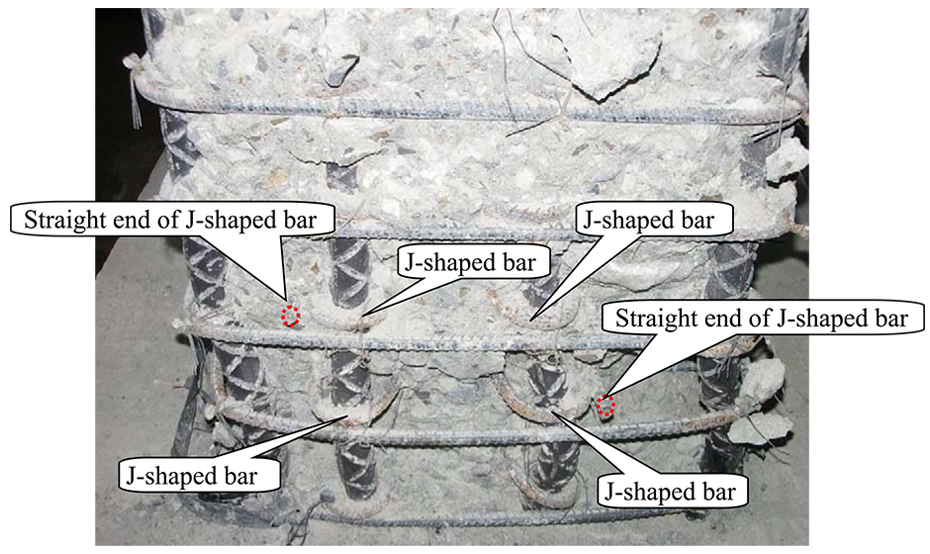
Appearance of the plastic hinge zone of Specimen H-330.
Conclusion and suggestions
Six large-scale RC column specimens were subjected to lateral cyclic loading tests to investigate the effect of horizontally lap-spliced crossties on the confinement of core concrete and the required lap splice length of lap-spliced crossties. The following conclusions were made on the basis of the results of this study:
The confining effect of horizontally lap-spliced crossties is similar to that of vertically lap-spliced crossties. The ductility of the specimens that adopted the lap-spliced crossties was comparable to that of the specimens using crossties featuring a 180° hook on the two ends.
Despite the lap splice length of the horizontally lap-spliced crossties used in this study not conforming to the design code requirement, the hysteretic behavior suggested that the confining effect of these crossties was superior to that of conventional crossties and comparable to that of one-piece crossties with 180° hooks at both ends.
Based on the results of this study, an innovative method for determining required lap splice length for lap-spliced crossties is proposed and the application of lap-spliced crosstie can be extended to the columns with smaller cross-section.
Using lap-spliced crossties in construction is easy, produces a low possibility of construction errors, and substantially improves the construction quality of RC column reinforcement and the seismic resistance capability of RC structures.
Footnotes
Acknowledgements
A grant, test sites, equipment, and administrative support were provided by the Architecture and Building Research Institute. The authors are grateful to the Architecture and Building Research Institute for their support.
Declaration of Conflicting Interests
The author(s) declared no potential conflicts of interest with respect to the research, authorship, and/or publication of this article.
Funding
The author(s) received no financial support for the research, authorship, and/or publication of this article.
