
Abstract
Due to the improvement of steel properties, many steel structures with attractive appearance emerge unceasingly. In this article, a new structure of steel octagon-web beam which has the similar appearance with honeycomb beam was presented. The mechanical characteristics of steel octagon-web beam under bending loads were analyzed theoretically. Based on the Vierendeel truss theory in deflection calculation of honeycomb beam, the deflection calculation method of steel octagon-web beam which was validated by finite element method was studied. Two parameters affecting deflection of steel octagon-web beam, such as opening type and expansion ratio, were analyzed. A scale model of steel octagon-web beam was manufactured in order to study bending behavior of the structure. The failure patterns of test specimen under four-point bending test are the buckling of deck and web. A nonlinear finite element model of test specimen whose results were compared with test was established by software ABAQUS 2017. The stresses of slabs under ultimate load have reached yield stress, which shows steel octagon-web beam has good flexural performance.
Keywords
Introduction
Steel bridge has a long history of construction and use, which is always one of the most competitive types of bridges in engineering. The advantages of steel bridges with large span are suitable for industrial manufacture, high strength, light weight, and good seismic performance. Therefore, steel bridges always play an important role in the field of bridge construction. Steel octagon-web beam (SOWB) is a new type of steel structures, whose top and bottom slabs are connected with regular octagonal steel plates by high-strength bolts. The web of SOWB is formed by regular octagonal steel plates connected by high-strength bolts, which has a similar appearance with honeycomb beam. SOWB can be used as emergency bridge, pedestrian bridges, landscape galleries, and so on. An SOWB model established by software ABAQUS 2017 (Dassault Systèmes, 2017), as shown in Figure 1.

A model of SOWB with 3D view established by ABAQUS 2017.
Generally, SOWB mainly consists of the following parts:
Top and bottom slabs: Slabs are made of Q235 steel plate. The stiffeners are welded on deck to avoid pressure buckling.
Web unit: Two regular octagonal steel plates are welded by four rectangular steel plates to form a web unit. Two rows of web units are arranged on two sides of bottom slab along the longitudinal direction. High-strength bolts ASTM A325 are used to connect the web units, which are also used to connect the web units with deck and bottom slab.
End: Two end structures with reinforcing ribs welded with slabs are hollow structures. Welding adopts full-length double-sided fillet weld, and foot size is 12 mm.
Compared with the traditional steel bridges, SOWB has the following characteristics:
Factory prefabrication: All parts of the structure can be manufactured by factory to ensure the quality of the members.
Reliable connection: The components in the structure are connected by high-strength bolts and do not need field welding. It not only greatly reduces the difficulty of manual work, but also effectively guarantees the reliability of the connection.
Convenient replace: The connections of the structure adopt high-strength bolts, the damaged component in the structure can be replaced quickly without taking up traffic for a long time.
Fast installation: Due to the factory prefabrication and the use of high-strength bolt connection, the structure can be quickly assembled and connected without long-term closed traffic on the erection site.
Due to the similar appearance of SOWB and honeycomb beam, it is instructive to summarize the research of honeycomb beams for SOWB.
The researches on honeycomb beam mainly focus on deflection calculation, failure modes analysis, ultimate bearing capacity of web buckling, and stress distribution of web buckling. Based on the elastoplastic and elastic buckling theory, a calculation formula of distortional buckling is proposed, whose results show good agreement with experimental results (Zirakian and Showkati, 2006). The lateral stability of honeycomb beams is investigated by using three-dimensional finite element (FE) modeling of simply supported I-shaped honeycomb beams with a broad spectrum of cross-sectional dimensions, span lengths, and web perforation configurations (Sweedan, 2010). The accuracy of nonlinear FE softwares in prediction of the ultimate and buckling loads of honeycomb beams is discussed, and the results show that ANSYS program has the highest accuracy (Gholizadeh et al., 2011). The buckling load of honeycomb beams can be reduced significantly by distortion of web, and the bearing capacity of honeycomb beams can significantly increase due to the use of high-strength steel (Ellobody, 2011). A robust variant of genetic programming was utilized to build a prediction model for the load capacity of castellated steel beams (CSBs) (Gandomi et al., 2011). An FE software was used to perform nonlinear buckling analysis of honeycomb beam with initial defects (Soltani et al., 2012). Mechanical experiments on four polymer-bonded honeycomb beams were conducted, and the effects of materials with different thicknesses on the failure modes of the entire structure were also discussed (Sebastian et al., 2012). An elastic stabilizing device for honeycomb beam which can significantly increase the structural rigidity and greatly increase the structural shear-resistance was proposed (Showkati et al., 2012). The behavior of honeycomb beams with two simply supported ends under moment gradient loading was numerically studied, and the effect of beam and braced lengths on rotational capacity of honeycomb beams was investigated (Daryan et al., 2013). An FE method to investigate the inelastic behavior of honeycomb beams under combined buckling modes was proposed (El-Sawy et al., 2014). An FE method to investigate the Vierendeel failure of CSBs with fillet corner web openings was adopted (Wang et al., 2014). A numerical model that was validated based on experimental results to investigate the lateral-torsional buckling behavior of honeycomb beams was proposed (Sonck and Belis, 2015). An analytical solution for calculating the critical buckling load of simply supported cellular columns when they buckle about the major axis was presented (Gu and Cheng, 2016). An FE method to obtain the correction factor for American Institute of Steel Construction (AISC) formula to calculate the critical moment of the honeycomb beam was proposed (Kwani and Wijaya, 2017). The fabrication processes with cutting and welding will significantly change the residual stresses of the honeycomb beam (Zhou et al., 2018).
The aim of the work is to do research bending behavior of SOWB in order to provide references for engineering application. Structural mechanical characteristics, deflection calculation method, and some parameters affecting deflection of SOWB were studied theoretically. In order to test the bending behavior of SOWB, the detailed design of honeycomb beam was used to improve and perfect SOWB. The failure patterns of SOWB which reflect the design rationality were obtained through four-point bending test. The load–deflection curves of SOWB that capture the structure characteristics were obtained. The stress distributions under yield load were described by a nonlinear FE model of SOWB.
Theoretical analysis on bending behavior of SOWB
Theoretical analysis on bending behavior of SOWB mainly includes the following three aspects: structural stress characteristics, deflection calculation method, and analysis of some parameters affecting the structure deflection.
Structural stress characteristics
The symbolic definitions of dimensions and internal forces involved in calculation are given, as shown in Figure 2.
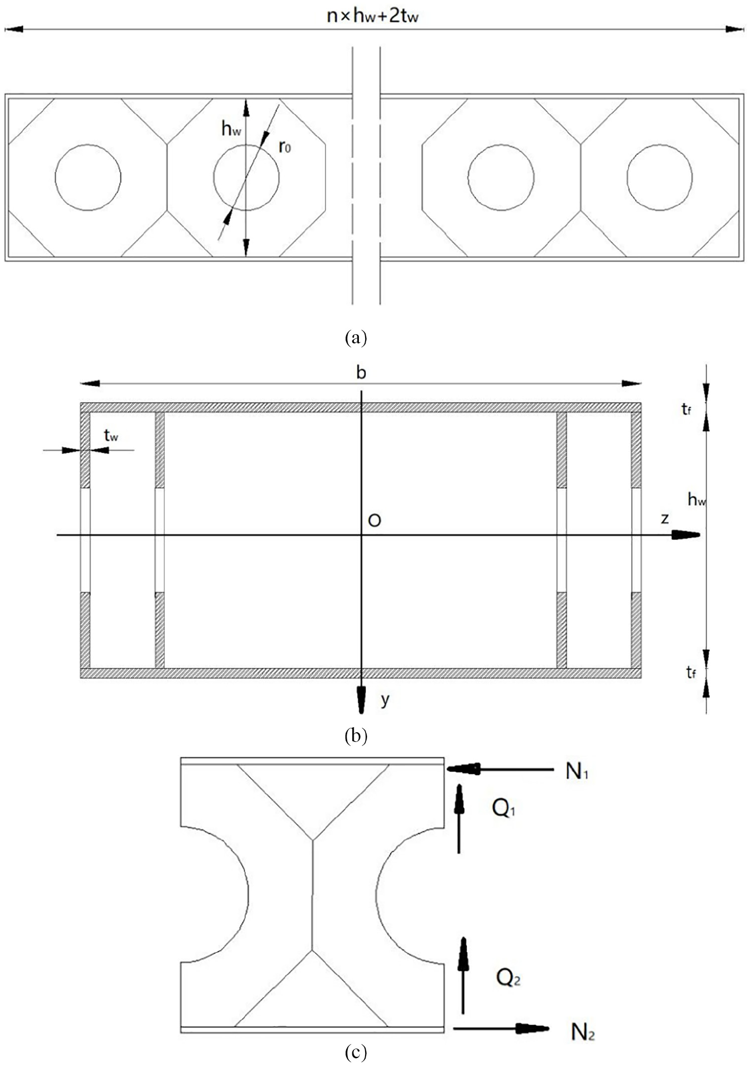
Symbolic definitions of dimensions and internal forces of SOWB: (a) geometry where
For regular octagonal steel plate,
where
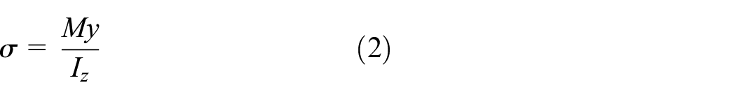
For deck,

where,
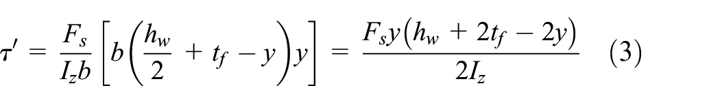
For bottom slab,


where
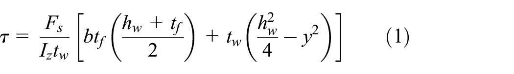
The cross-section of a simply supported SOWB under bending loads would produce axial forces and shear forces resisting bending deformation. According to the cross-section characteristics of SOWB, the axial forces and shear forces can be divided into two parts as defined in Figure 2(c). The internal forced can be obtained as following

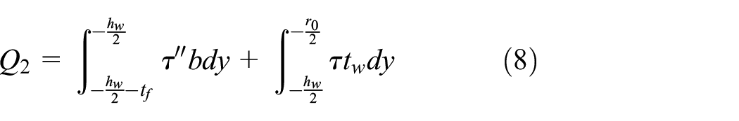

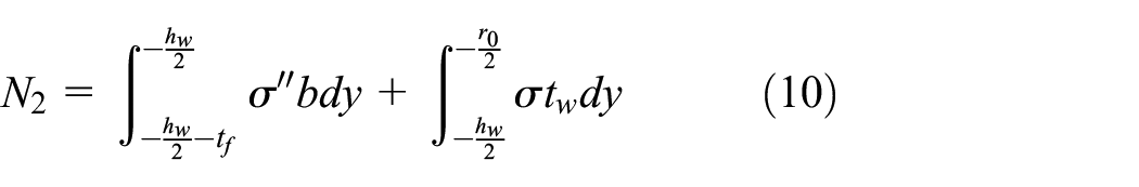
where
In Equation (7), the value of second term represents shear force of deck can be omitted. Similarly, some items are also negligible in Equations (8) to (10). Therefore, the internal forces can be expressed as follows
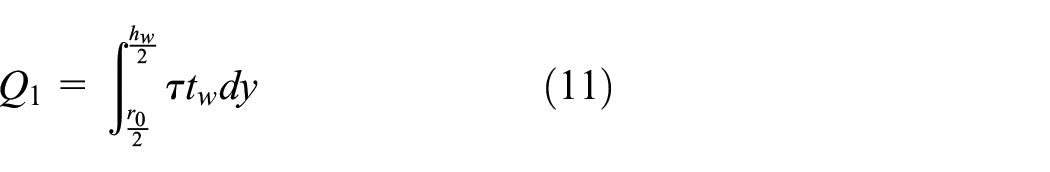
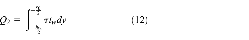
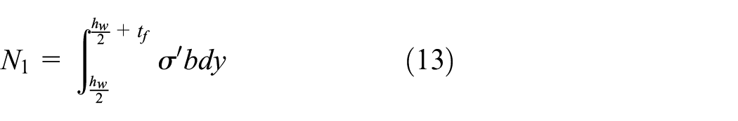
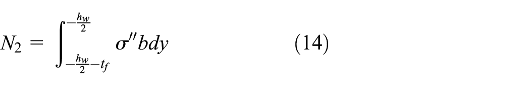
From Equations (11) to (14), it can be seen that slabs mainly bear axial forces and regular octagonal steel plate mainly bears the shear force under bending loads.
Deflection calculation method
Assumptions
Due to the open-web of SOWB, the theory of Euler beam (Shames and Dym, 1985) which ignores shear deformation is not suitable for deflection calculation of the structure. Hence, the theory of Timoshenko (1921, 1922) beam which considers the effect of shear force on deflection should be employed.
The following assumptions were adopted in deflection calculation of SOWB.
The cross-section of SOWB always remains plane before and after deformation.
The shear force on cross-section is distributed to regular octagonal steel plate according to the shear stiffness.
SOWB can be divided into some structure units according to the characteristics of the structure, and the deflection of the structure can be obtained by superposition of the unit deflection.
Deflection calculation of SOWB
An SOWB has the length of L, height of H, which consists of n regular octagonal steel plates, as depicted in Figure 3. Therefore, the relationship between length and beam height is

An SOWB model.
The deflection of SOWB

Bending deflection
For illustration purposes, the cross-section of the structure is divided into two categories according to the structural characteristics of the web. One is the cross-section where the top and bottom slabs meet the web (section 1#), and the other is the cross-section where the top and bottom slabs do not meet the web (section 2#). Assuming that the equivalent moment of inertia of cross-section for section 1# is
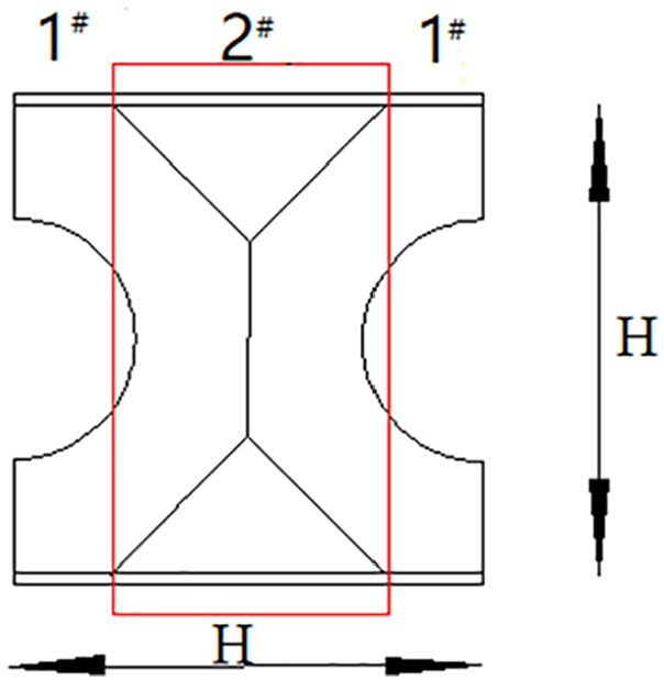
Schematic diagram of web unit.
Therefore, the cross-section stiffness
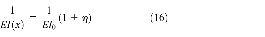
where,
For
For

where
According to Maxwell–Mohr method, the calculation formulas for bending deflection can be expressed by Equation (19). Equation (19) only considers the deflection caused by bending moment and ignores the effects of shear force and axial force

in which,
According to the structural characteristics of SOWB, Equation (20) can be obtained by piecewise integrated and summation of Equation (19)

The proportion of length of section 1# part to total length is
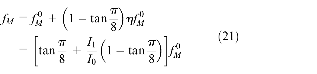
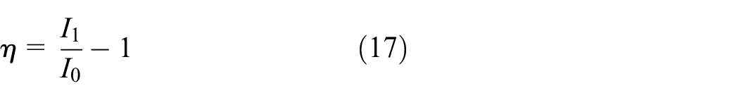
where
Deflection of shear secondary moment
In order to calculate the deflection of secondary shear moment
Assuming that shear force of one web beam is Fi, and the left half of web unit is taken out as research object (see Figure 4), and the bending deformation

in which
The deflections
where

Calculation diagrams of bending deformation
The bending deformation
The lower right part of web unit is taken out as research object (see Figure 4), and the rotational deformation
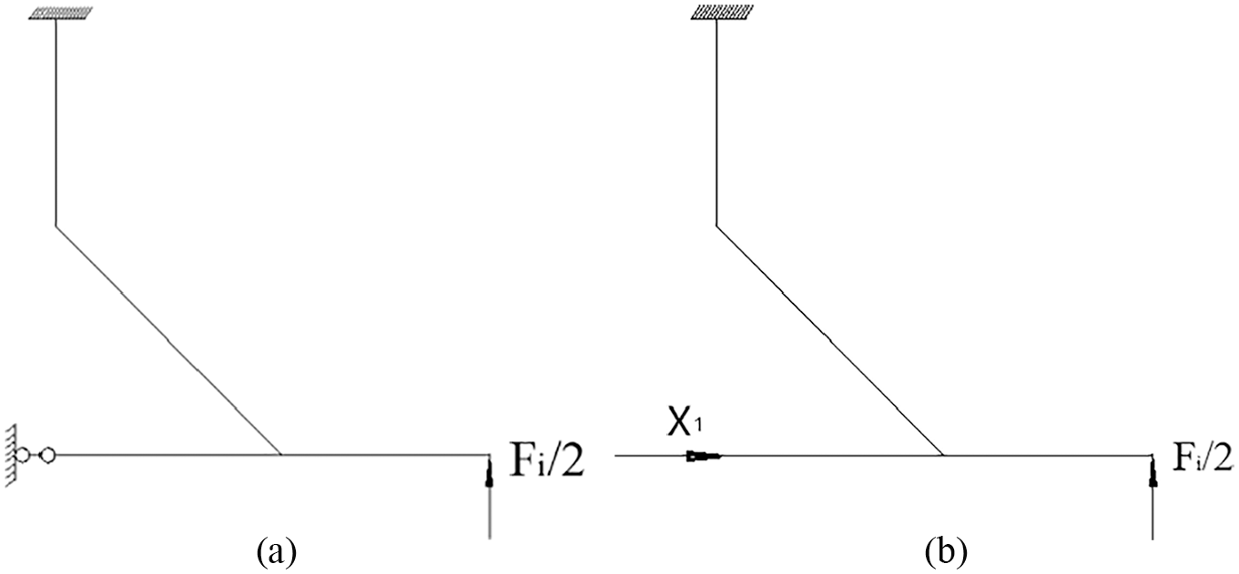
Calculation diagrams of rotational deformation
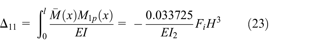
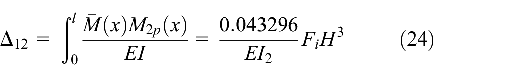
According to the principle of virtual displacement, the redundant constraint

in which,
The deflections

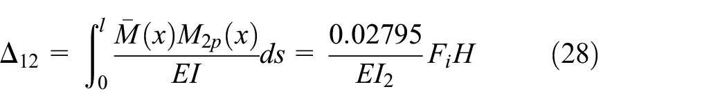
The rotational deformation
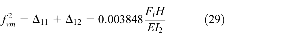
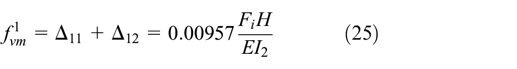
The deflection of shear secondary moment
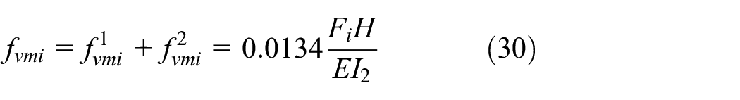
Therefore, the calculation formula of SOWB can be expressed as Equation (31)
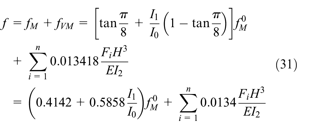
where n represents the number of regular octagonal steel plates in the longitudinal direction; I2 is moment of inertia of cross-section for regular octagonal steel plate; I1 is the equivalent moment of inertia of cross-section in section 1# part; I0 is the equivalent moment of inertia of cross-section in section 2# part; Fi is shear force in one web unit; H is height of regular octagonal steel web; E is modulus of elasticity.
Validation
In order to verify the accuracy of the deflection formula, an FE model of cantilever SOWB was established by ABAQUS 2017.
The cantilever SOWB has the length of 890 mm, the depth of 89 mm, and the width of 200 mm, and a vertical force of 1000 N is applied on free end. The thicknesses of all components are 3 mm, and the diameter of circular opening of regular octagonal steel plate is 40 mm. The properties of steel are elastic modulus of 210 GPa, Poisson’s ration of 0.3 and shear modulus 80.769 GPa. The junctions in the structure have no relative displacement, such as the adjacent regular octagonal steel plates, top, and bottom slabs.
S4R element which is a four-node curved shell reduced integral element was used to mesh the model. The deflection of finite element analysis (FEA) model is
The deflection of SOWB at free end can also be obtained by Equation (31). In Equation (31),
There are 10 regular octagonal plates from free end to fixed end, so the deflection of SOWB at free end can be expressed as Equation (33)

The resulting error between FE model and formula is 0.71%.
The deflections calculated by FE model and formula under different load forms and boundary conditions were summarized to verify the accuracy of proposed deflection formula further, as shown in Table 1.
The deflection of FE model and formula under different forms and boundary conditions.
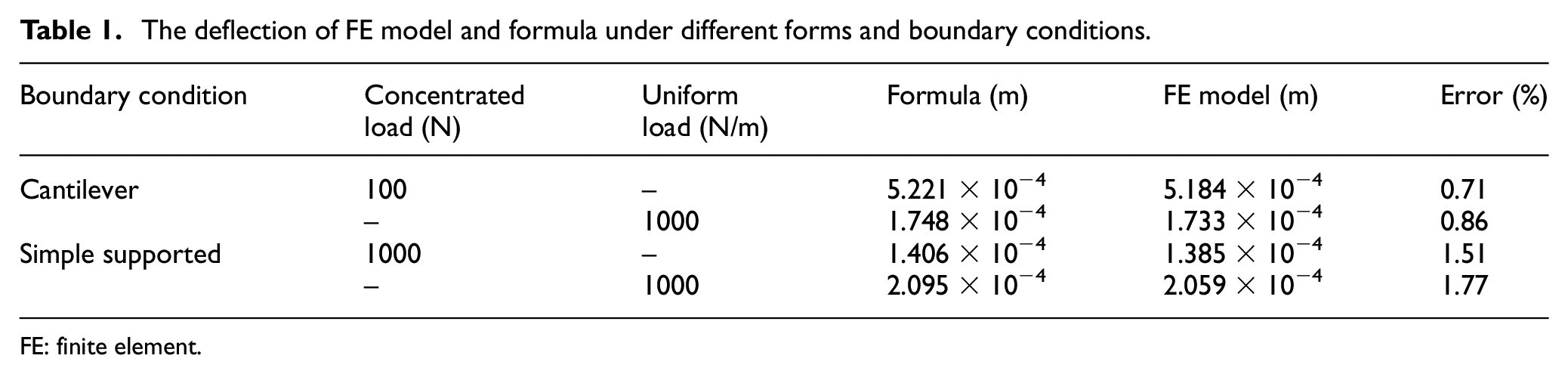
FE: finite element.
From Table 1, it can be seen that the errors between the deflections calculated by formula and FE model are less than 3%. Therefore, the proposed deflection calculation method is feasible for deflection calculation of SOWB.
Analysis of two parameters affecting the structure deflection
The relevant parameters affecting the deflection of SOWB were analyzed, such as opening type and expansion ratio.
An FE model of SOWB
An FE model of SOWB established by ABAQUS 2017 was adopted to analyze the parameters affecting the structure deflection. The model has the length of 5 m, height of 0.33 m and width of 1 m. The components of SOWB have thickness of 0.015 m. Regular octagonal steel plate with 0.15 m diameter circular opening has height of 0.3 m. S4R element which is a four-node curved shell reduced integral element was used to mesh the model.
Opening type
The vertical force with a concentrated load of 2250 N acted on the free end. Three opening types, including circular, regular hexagon and regular octagon, were considered, respectively. The regular octagon, regular hexagon, and circular are tangent. Boundary conditions and other parameters in the models were consistent with the aforementioned model.
Table 2 shows comparison of free end deflections under different opening types. From Table 2, it can be seen that the free end deflection of the model with regular hexagonal opening is 5.226 × 10⁻⁴ m. The free end deflection of the model with regular octagon opening is 5.207 × 10⁻⁴ m, which is slightly smaller than that of the model with regular hexagonal opening, with an error of 0.36%. The deflections at the free end of the two models with regular polygon opening are slightly larger than that of the model with circular opening.
Comparison of free end deflections of different opening types.
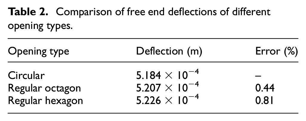
When regular polygon opening is adopted for the web, the deflection at free end decreases gradually with the increase in the number of edges. When the circular opening is adopted, the deflection at the free end is the smallest.
Because the regular hexagon and regular octagon are tangent to the circular, the hollow area of the web with regular polygon opening is slightly larger than that with circular opening. Hence, the web stiffness with circular opening is slightly larger than that with regular polygon openings.
Expansion ratio
Expansion ratio refers to the ratio of web height to opening height. Six FE models with expansion ratios of 2.4, 2.2, 2.0, 1.8, 1.6, and 1.4 were established, respectively. Circular opening was adopted for the models. Boundary conditions, loads, and other parameters in the models were consistent with the aforementioned model.
Figure 7 shows the relationship between expansion ratio and deflection. With the increase in the expansion ratio, the stiffness of the web increases gradually, so that the deflection of the free end decreases gradually. When the expansion ratio is 1.4, the free end deflection is 0.5979 mm; when the expansion ratio is 2.4, the free end deflection is 0.5149 mm.
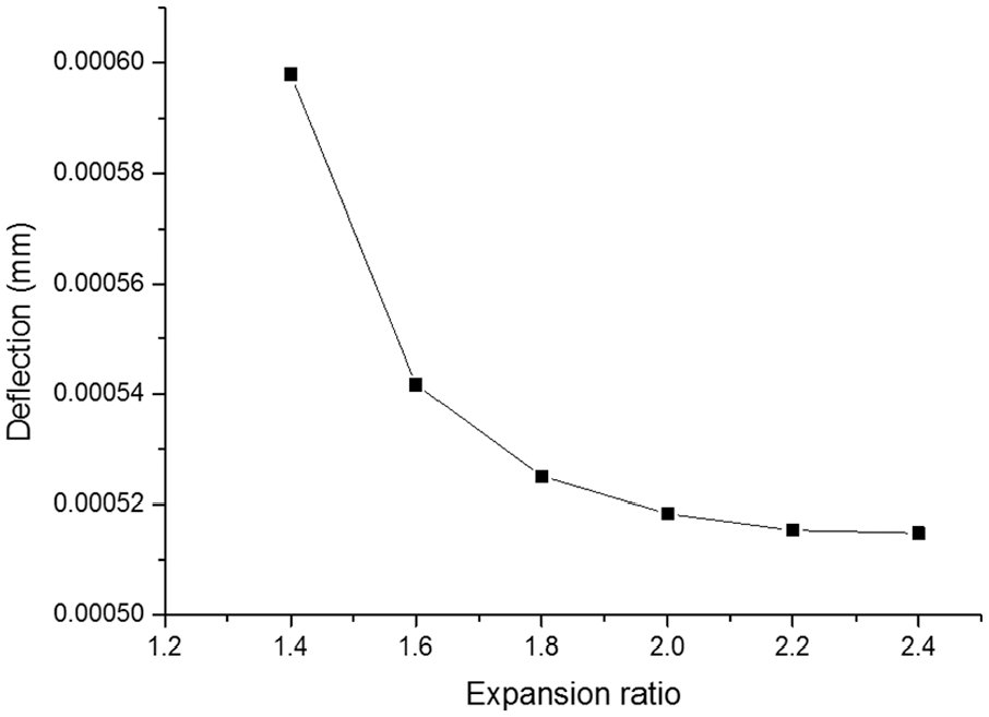
Relationship between expansion ratio and deflection.
As the expansion ratio increases, the free end deflection changes gradually flat. For example, when the expansion ratio is 1.8, the free end deflection is 0.5251 mm; when the expansion ratio is 2.4, the free end deflection is 0.5149 mm. It can be attributed to the fact that when the expansion ratio increases to a certain extent, the effect of increase of web stiffness is no longer obvious. Therefore, the structure deflection can be reduced by increasing the expansion ratio in a certain range. However, the structure deflection does not change significantly when the expansion ratio reaches or exceeds a certain extent. Hence, the reasonable expansion ratio for SOWB should be within the range of 1.8–2.2.
Bending test of SOWB
Design of the SOWB
A test specimen of SOWB was manufactured in order to study the bending behavior, which was designed in reference to the specification of steel structures (GB 50017-2003, 2003). Except the connections between the end structures and the top and bottom slabs are welded, the connections between the other components are made of high-strength bolts.
Figure 8 shows schematic diagrams of SOWB. SOWB has length of 5000 mm, width of 800 mm, and depth of the 308 mm. The thickness of all components is 4 mm. The stiffeners welded on deck have height of 40 mm. The regular octagonal steel plate has height of 300 mm, side length of 124.26 mm, and the diameter of circular opening of 140 mm. Two transversely adjacent regular octagonal steel plates are welded with four steel plates to form web unit (see Figure 8(d)).
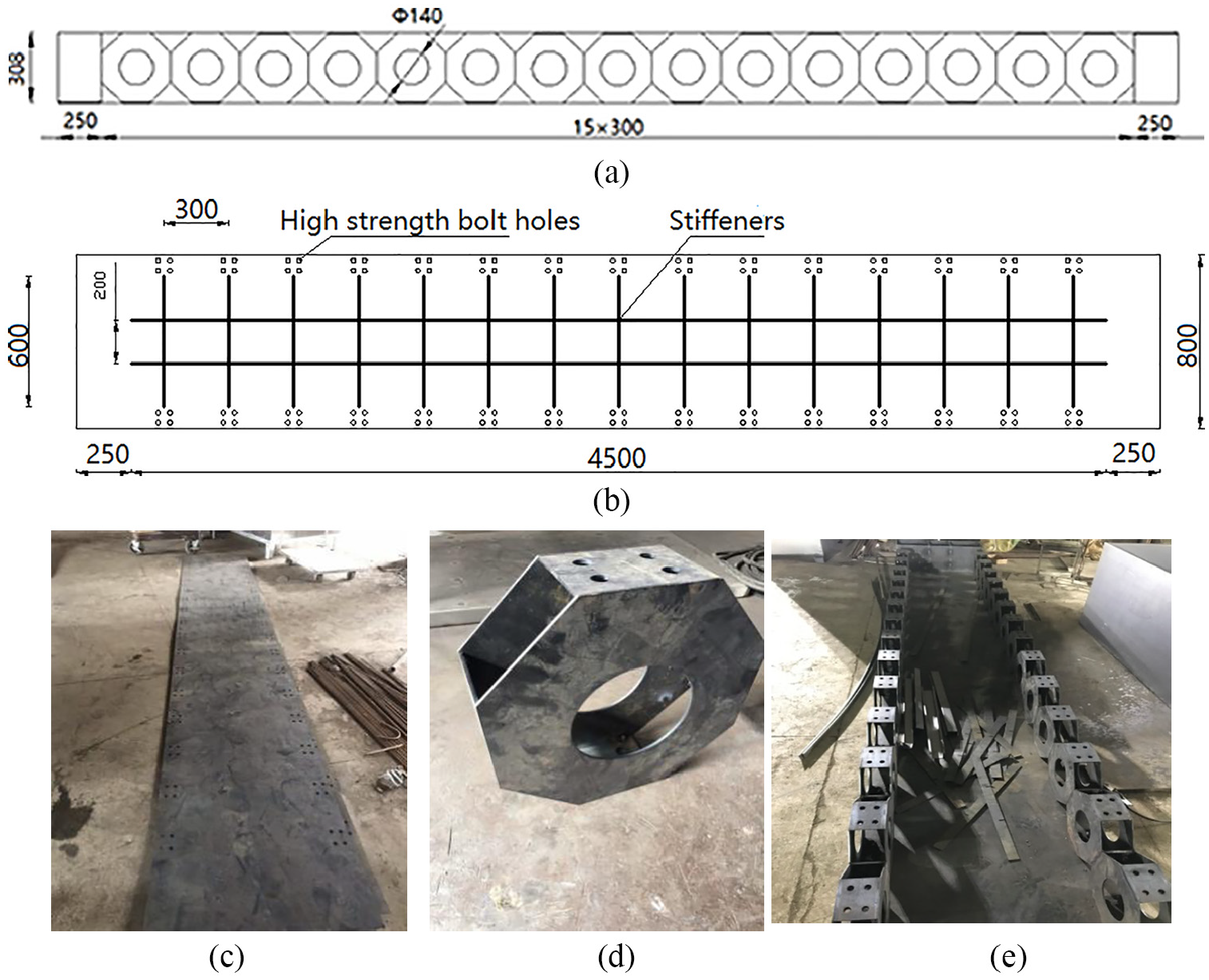
Schematic diagrams of SOWB: (a) elevation of SOWB (unit: mm), (b) plan of deck (unit: cm), (c) bottom slab, (d) web unit, and (e) SOWB in fabrication.
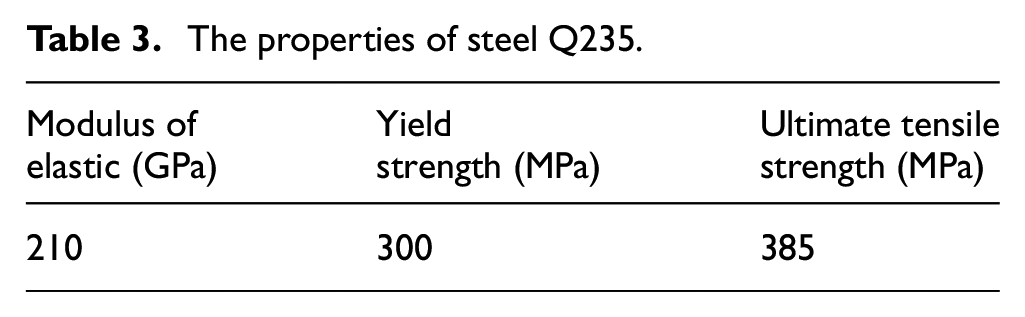
The mechanical properties of steel Q235 for SOWB were obtained through tension test as shown in Table 3. Steel Q235 has the density of 78
The properties of steel Q235.
Four-point bending test
Test preparation
Test equipment for four-point bending test is shown as Figure 9. The hydraulic jack was used to load, and the loading values were measured by pressure sensor. The distance from the support to the loading position was 1775 mm, and the distance between two loading points is 1200 mm. The strain gauges at top and bottom slabs of mid-span and loading points were recorded by the static resistance strain indicator TDS 303. In order to monitor the deformation of the specimen, six displacement sensors were placed in the middle span and near the supports.

Test equipment and specimen for two-point loading: (a) test layout and (b) static resistance strain indicator TDS 303.
Test process
A preloading of 30 kN was applied on test specimen in order to eliminate the clearance of assembling and to check the reliability of the test devices. The monotonic loading was applied on test specimen, which increases 30 kN at a time. Figure 10 is load–deflection curve under four-point bending load, which can be identified three distinct consecutive stages.
Stage I—below 90.22 kN. The deformation of test specimen is relatively small, and the load–deflection relationship can be seen linear.
Stage II—between 90.22 and 179.78 kN. The load–deflection relationship can be considered as semi-linear. The deformation of test specimen is relatively large. The deflection is 17.1 mm under the loading of 179.78 kN.
Stage III—between 179.78 and 236.50 kN. The load–deflection relationship is obviously a curve. The test specimen produces a larger abnormal sound and the deck near two loading points shows a slightly local buckling under the loading of 183 kN.
After Stage III, the increased rate of deflection is obviously accelerated. The test specimen lost the bearing capacity according to the loading failure of the hydraulic jack. The deck near two loading points buckled obviously (see Figure 11), and the web also buckled due to the deformation of the deck. In order to avoid safety problems caused by the sudden failure of the specimen, the test was terminated.

Load–deflection curve under four-point bending load.

Failure patterns of test specimen: (a) deck and (b) web.
Comparisons between deflection calculation method and test results
According to the loading mode, the test specimen can be simplified to a calculation model of simply supported beam as shown in Figure 12. The deflections of the specimen under different loads can be calculated by the proposed deflection calculation method.
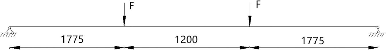
Simplified mechanics model of test specimen (unit: mm).
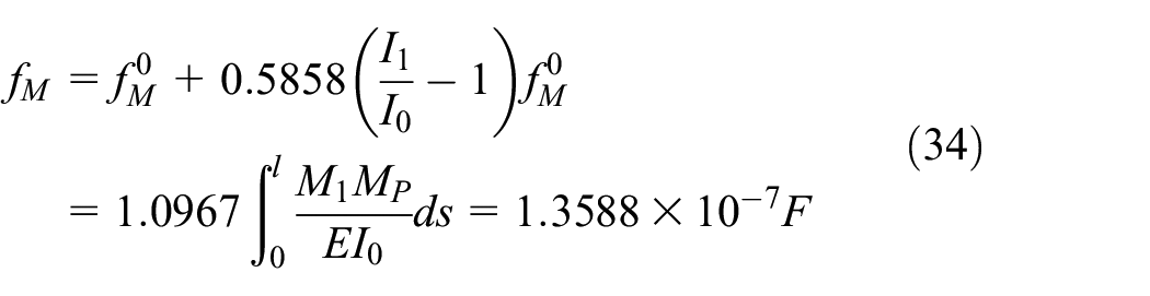
The bending deflections of specimen under different loads can be calculated by Equation (34)
The deflections of shear secondary moment in one web unit under different loads can also be calculated by Equation (35)
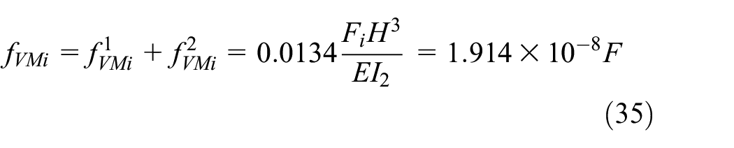
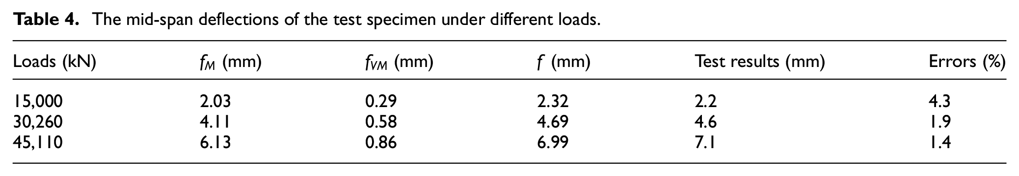
Table 4 shows the mid-span deflections of the test specimen under different loads, which was obtained by proposed calculation formula and test, respectively. From Table 3, it can be seen that the proposed deflection formula is accurate in calculating the deflections of test specimens in the stage of elastic deformation, and the errors are less than 5%.
The mid-span deflections of the test specimen under different loads.
Bending behavior of SOWB based on ABAQUS 2017
An FE model of SOWB
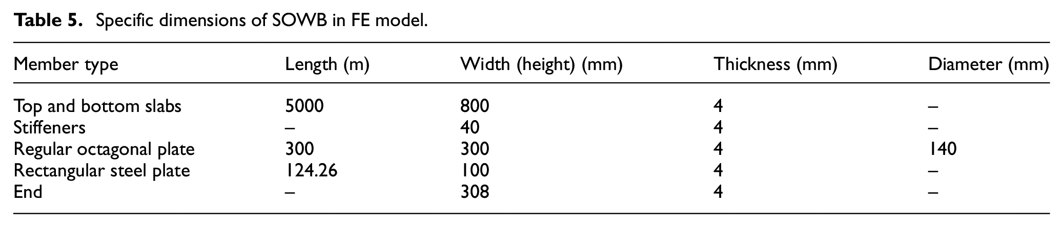
An FEA model of SOWB was established by ABAQUS 2017, as shown in Figure 13. The specific dimensions of the members in FE model are consistent with those of test specimen, as shown in Table 5. In order to ensure the convergence of calculation, the high-strength bolt holes of top slab, bottom slab, and web units were ignored in FE modeling. The deflections of SOWB under different loads were obtained by applying 5-mm displacement load to FE model.

An FE model of SOWB established by ABAQUS 2017.
Specific dimensions of SOWB in FE model.
Steel constitutive law and mesh
In order to study nonlinear behavior of SOWB, the constitutive law of double broken line was adopted for steel Q235. In mesh generation of slabs and stiffeners, stiffeners are subordinate surface and slabs are main surfaces. In mesh generation of slabs and ends, ends are subordinate surface and slabs are main surfaces. In mesh generation of slabs and rectangular steel plates, rectangular steel plates are subordinate surface and slabs are main surfaces. In mesh generation of regular octagonal plates and rectangular steel plates, regular octagonal plates are subordinate surface and rectangular steel plates are main surfaces.
The mesh of ends, stiffeners, and rectangular steel plates are larger than that of regular octagonal plates, but less than that of slabs. All members such as slabs, regular octagonal plates, and ends were modeled by S4R element. S4R can be used to model thin or thick shells and is a four-node curved shell element. S4R element employs a reduced integral method and includes hourglass mode control, which is suitable for large strain and strain gradient. The nonlinear FE model of SOWB has been discretized by 18,718 shell elements.
Simplification of connection and boundary condition
Tie constraint is used to simulate welding and bolting for junctions in the specimen, which can also be applied to face-to-face constraints. In data transmission of stiffness between two faces, tie constraint is equivalent to rigid connections and the stiffness is relatively large. Hence, there is no relative motion and deformation in the binding area.
Two reference points were adopted to simulate the position of hydraulic jack, which were coupled with two bearing part on deck. Two concentrated loads were applied at two reference points to simulate the loading of hydraulic jack. Two ends of SOWB which limit the vertical displacement of test specimens and satisfy the simple support constraint are placed on two supports. Hence, the boundary condition of SOWB can be seen as the simple supported.
Analysis of FE model and test results
An FE model of SOWB under four-point loading was established by software ABAQUS 2017.
Comparison between FE model and test results
Loading-deflection curve
The yield loads, yield deflections, ultimate loads, and ultimate deflections of test and FE model under four-point bending test are presented in Table 6, and load–deflection curves of four-point loading obtained by test and FE model are shown in Figure 14. From Figure 14, it can be seen that the initial stiffness of FE analysis agrees well with that of test, which shows that the clearance by assembling in structure has been eliminated through preloading. Overall, two load–deflection curves coincide basically, which reflects the high reliability of FE model. The effect of initial structural defects on mechanical properties becomes more and more prominent with the increase in the load, which results in the difference between test and FEA after yield load.
The yield loads, yield deflections, ultimate loads, and ultimate deflections of test specimen and FE model under four-point bending test.
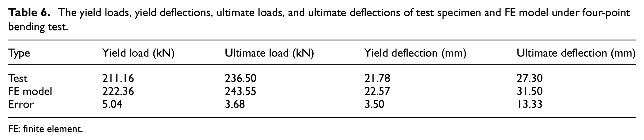
FE: finite element.

The load–deflection curves of four-point loading.
The yield loads of test and FE model are 211.16 and 236.50 kN, and the yield deflections of test and FE model under the yield loads are 21.78 and 22.57 mm, respectively. The errors between yield loads and yield deflections obtained by test and FE model are 5.04% and 3.50%, respectively. The ultimate loads of test and simulation are 236.50 and 245.53 kN, respectively. The deflection of test under the ultimate load is 27.30 mm, which is smaller than that of FE model. The errors between ultimate loads and ultimate deflections obtained by test and FE model are 3.68% and 13.33%, respectively. When the bearing capacity of test specimen approaches ultimate load, the bearing capacity of the structure decreases rapidly due to the serious buckling of deck.
Strain contrast
Figure 15 shows the relations between loads and strains for test and FE model. The load–strain curves of test and FE model fit well on the whole, especially for the strains on the mid-span (Figure 15(a), (b), and (d)). The load–strain curve at the loading point of deck shows the same trend (Figure 15(c)). With the gradual increase of loading, the stress state of deck at loading point was changed from compression to tension. The local buckling occurs at loading point with the increase of loading, resulting in the transformation of the strain from compression to tension.
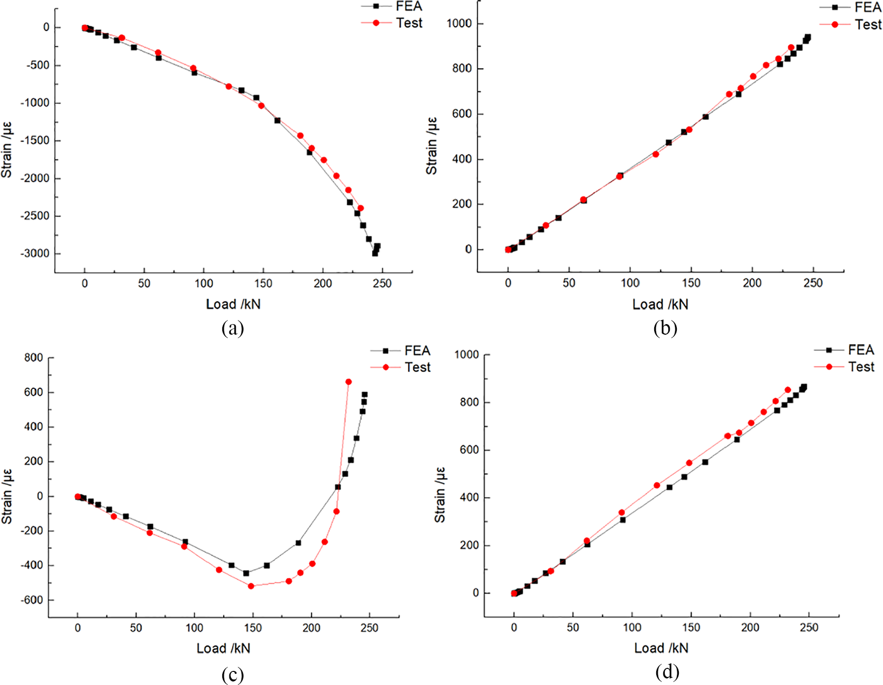
Comparison of load–strain curves obtained by test and FE model: (a) load–strain curves on the mid-span of deck, (b) load–strain curves on the mid-span of bottom slab, (c) load–strain curves at the loading point of deck, and (d) load–strain curves at the loading point of bottom slab.
Stress distribution
Figure 16 shows the stress distribution of SOWB under the ultimate load 236.50 kN. From Figure 16, it can be seen that the stresses near the areas of two loading points are close to 350 MPa. The stresses of slabs in pure bending section are mainly 200 and 210 MPa, respectively, and the stresses of slabs exceed the design strength of Q235. If the effect of the web of the specimen was ignored, the ultimate bearing capacity of the specimen, which was about 240 kN, can be calculated from the stress values of the slabs, which is close to the ultimate load value of 236.50 kN obtained from test.

The stress distribution of SOWB under four-point loading.
Comparison of failure patterns
Figure 17 shows failure patterns obtained by test and FEA are consistent with each other. The ideal failure pattern of test specimen is that the stresses of slabs reach the yield stress. The failure of the specimen was caused by the buckling of the deck and web. At this time, the stresses of the slabs reach the design strength of steel Q235. Generally speaking, the loading of the specimen has approached ultimate bearing capacity, which shows that the structure has good flexural bearing capacity.
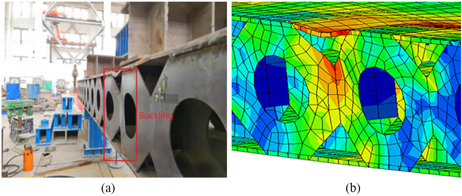
The failure patterns of SOWB under four-point loading obtained by (a) test and (b) FE model.
Conclusion
This article studies the bending behavior of SOWB. The structural stress characteristics, deflection calculation method, and some parameters affecting deflection of SOWB were analyzed. The failure modes of test specimen of SOWB under four-point loading were also obtained. By means of theoretical analysis, test, and FE model, the bending behavior of SOWB was studied, and the following conclusions were drawn:
Through the study of structural stress characteristics of SOWB, it can be found that slabs mainly bear axial forces and the regular octagonal steel web mainly bears the shear force under bending loads.
Based on the Vierendeel truss theory, the deflection calculation formula was proposed and validated by FE method. The errors between the deflections obtained by proposed formula and FE method are less than 3%, from which it can be considered that the proposed formula is feasible for deflection calculation.
Two parameters affecting the deflection of SOWB were analyzed: opening type and expansion ratio. The results show that when the web adopts circular opening, the deflection is the smallest; when the expansion ratio reaches a certain extent, the effect of the decrease of the deflection is not obvious. The reasonable expansion ratio should be in the range of 1.8–2.2.
The failure pattern of test specimen under four-point loading is the buckling of deck and web. The yield load and deflection of test are 211.16 kN and 21.78 mm, respectively, which are slightly less than those obtained by FEA by 5.03% and 3.50%. The ultimate load and deflection of test are 236.50 kN and 27.30 mm, respectively, which are slightly less than those obtained by FE model by 3.67% and 13.33%. The effect of initial structural defects on mechanical properties becomes more and more prominent with the increase in the load, which results in the difference between test and FE model after yield load.
The stresses of slabs under ultimate load exceed the design strength of Q235, which shows SOWB has good bending behavior. The stresses near the loading areas are close to 350 MPa. The stresses of top and bottom slabs in pure bending section are mainly 200 and 210 MPa, respectively. It can be concluded that the SOWB has good bending behavior through bending test and is worth further study for application. Compared with the other ordinary girder solutions, SOWB still has some problems such as heavy deck, high cost, and complex fabrication that need to be solved in further study.
Footnotes
Declaration of Conflicting Interests
The author(s) declared no potential conflicts of interest with respect to the research, authorship, and/or publication of this article.
Funding
The author(s) received no financial support for the research, authorship, and/or publication of this article.