




Abstract
Fiber-reinforced polymer composites have been widely used to design fiber-reinforced polymer–based confined concrete columns with potential benefits. However, it is critical to design a column with sufficient post-peak performance that can prevent its collapse at the rupture of the fiber-reinforced polymer tube. This article presents the experimental results on the prior and post peaks behavior of concrete-filled double-skin tubular columns with basalt fiber-reinforced polymer (BFRP)–punched-in outer steel and BFRP-circular inner steel (BFST-DSTCs). Twenty-two specimens were tested under axial compression to investigate the effects of design parameters on the behavior of the BFST-DSTC. The outcomes reveal that the BFST-DSTC exhibits the best performance in terms of load capacity, confinement ratio, failure and damage mechanisms, and ductility in prior and post peaks. The inner fiber-reinforced polymer jacket delays the buckling of the inner tube. The punched-in patterns of the outer steel improve the confinement effectiveness of the fiber-reinforced polymer jacket. The BFST-DSTC displays a good post-peak performance with high-energy dissipation capacity that prevents the concerned structure from collapse after the fiber-reinforced polymer jacket rupture. Finally, a new confinement model is proposed to predict the ultimate point of the confined concrete.
Keywords
Introduction
Fiber-reinforced polymer (FRP) composites have been widely used to enhance the mechanical performance of structural elements under compression, flexural, and seismic loading (Lim and Ozbakkaloglu, 2015; Ozbakkaloglu, 2012; Shao and Mirmiran, 2004). Several FRP-based confined concrete columns have been developed, including concrete-filled FRP tube (CFFT), FRP-confined concrete-filled steel tube (CFCT), and the hybrid FRP-concrete-steel double-skin tubular column (hybrid DSTC). The hybrid DSTCs display potential benefits such as high load capacity, and good ductility behavior under different loading conditions before the rupture of the FRP tube (Idris and Ozbakkaloglu, 2014; Louk Fanggi and Ozbakkaloglu, 2013; Ozbakkaloglu and Louk Fanggi, 2014; Teng et al., 2007; Wong et al., 2008; Zhang et al., 2015). However, FRP-based confined concrete columns should display a good post-peak performance after the rupture of the FRP tube to avoid structural collapse. Consequently, it is significant to develop FRP-based confined concrete columns with a balanced prior- and post-peak performance.
The inward buckling of the inner tube depends on the amount of the outer FRP layers (Louk Fanggi and Ozbakkaloglu, 2013; Ozbakkaloglu and Louk Fanggi, 2014; Wong et al., 2008). The ductility of the hybrid DSTC is related to the rupture strain of the FRP. Yu et al. (2017) find a positive correlation between the rupture strain of the outer cylinder and the ductility performance of the hybrid DSTC, that is large rupture strain leads to high ductility. However, the real application of the hybrid DSTC is still limited due to the serious inward buckling of the inner tube, the sudden failure of the outer FRP, and the absence of the post-peak strength.
FRP-strengthened steel tube solves the brittle failure mode observed in CFFT (Deng et al., 2017). Such a well-known technique enhances the load capacity and the corrosion issue of the steel (Teng and Hu, 2007). The outer FRP jacket reduces or even suppresses the local buckling of the steel in the CFCT (Wei et al., 2014). However, the gap (between the sandwiched material and the steel tube due to concrete shrinkage) reduces the outer FRP confinement efficiency. Huang et al. (2016) perforated the steel confinement to improve the confinement efficiency of the glass-FRP (GFRP) wraps. They found an increase of the confinement effectiveness with a gradual descending branch after the rupture of the FRP. However, they have not considered the post-peak behavior that prevents the full-damage of the confined concrete beyond the maximum load capacity.
The use of corrugated plates in concrete-filled double steel tube (CFDST) distinguished their performance from ordinary CFDSTs in extreme events. Farahi et al. (2016) implemented external corrugated steel skin to increase the dissipated energy capacity of CFDST. On the other hand, basalt FRP (BFRP) offers some advantages when compared with the traditional carbon, glass, and aramid FRP. BFRP is environmental friendly with high-temperature resistance properties (Bhat et al., 2018). The energy absorption of BFRP is better than glass and carbon due to their different failure mechanism (Raj et al., 2017). BFRP composites have been deployed in concrete structures to replace internal steel rebars (Ibrahim et al., 2017; Sim et al., 2005). However, the use of BFRP in confined concrete is limited for CFFT and CFCT (Ciniņa et al., 2012; Suon et al., 2019; Wei et al., 2014).
To overcome the aforementioned challenges, this article proposes a novel form of double-skin tubular column named “BFST-DSTC” with outer BFST-punched-in steel and inner BFST-circular hollow steel. The proposed composite columns consider the confinement efficiency, the post-peak performance, and the abrupt failure mechanism of the hybrid DSTC at the rupture of the FRP tube. The use of FRP jacket reduces or delays the buckling of the inner tube, and mainly enhance the post-peak behavior. Axial compressive tests conducted on 22 scaled-specimens investigate the behavior and performance of the future double-skin tubular system in prior and post peaks. Some modeling work with regard to predicting the compressive strength and strain at the maximum load is presented. Test results reveal that the BFST-DSTCs with punched-in pattern exhibit the best mechanical performance at the prior and post peaks. The inner FRP layer delays the buckling mechanism of the inner steel tube. In addition, the high post-peak strength of the BFST-DSTCs can prevent collapse of the concerned structure in case of extreme events.
Experimental program
Test specimens
The test specimens included fourteen BFST-DSTCs with punched-in pattern, two normal BFST-DSTCs, four hybrid DSTCs, and two CFDSTs. They had an outer diameter (Do) of 150 mm, measured at the concrete core, and a height of 305 mm. The inner tubes of the BFST-DSTCs were made of FRP-circular steel. The BFST-DSTCs with punched-in pattern had an outer FRP-punched-in steel tube, whereas the normal BFST-DSTC had an outer FRP-circular steel skin. Figure 1 illustrates the cross-sectional design for the specimens. The specimens were designed based on the following parameters: inner and outer FRP wrap layers (nif and nof), thickness of the inner and outer steel (tis and tos), type of the FRP, concrete strength, and the presence of punched-in pattern. Table 1 provides the specimen details.
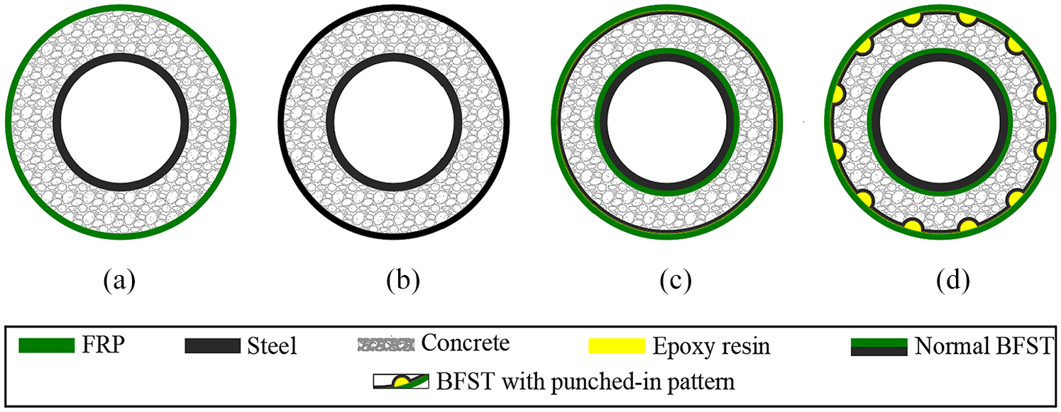
Cross-sectional design of (a) Hybrid DSTC, (b) CFDST, (c) normal BFST-DSTC, and (d) BFST-DSTC with punched-in pattern.
Specimen details.
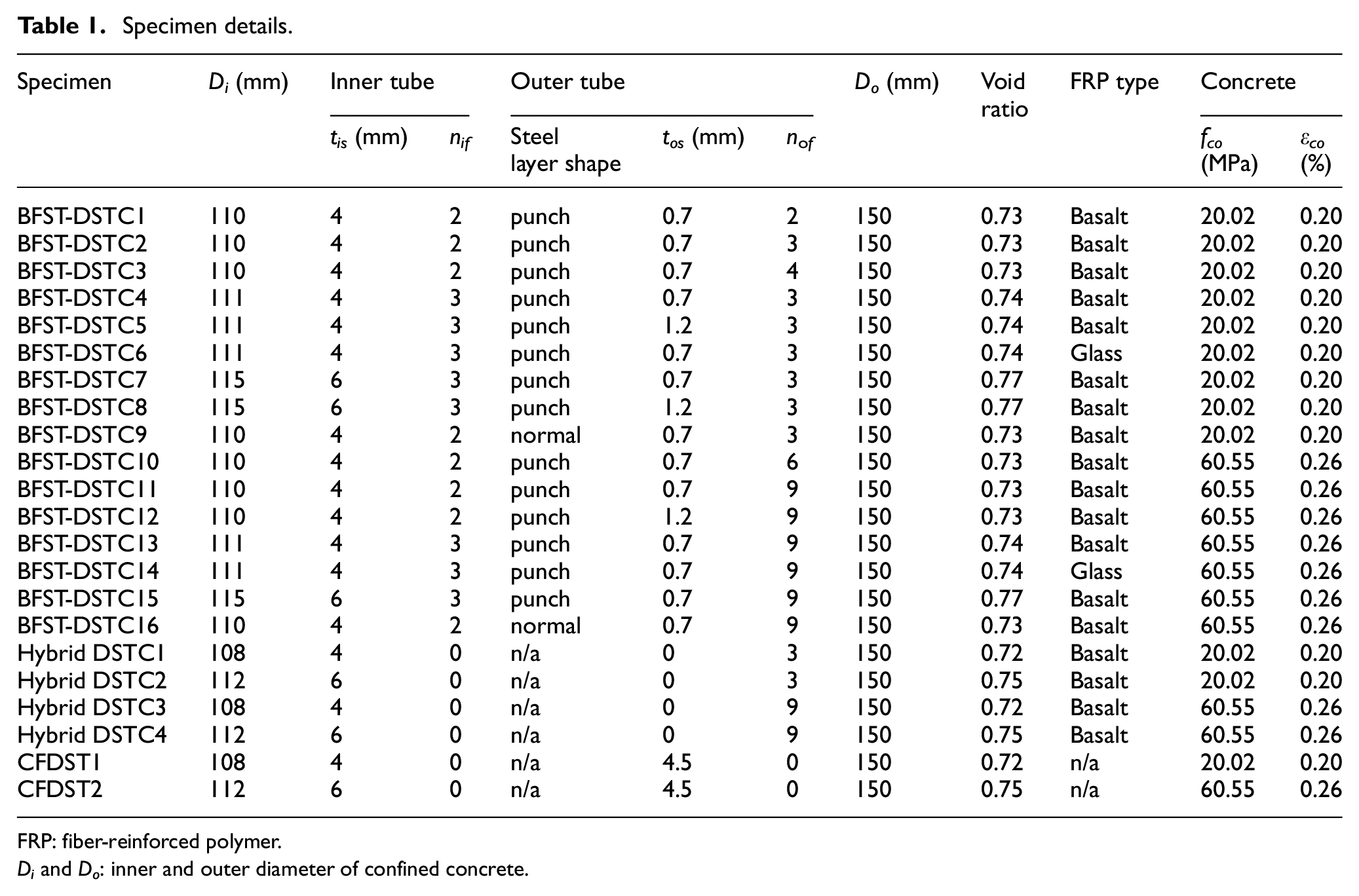
FRP: fiber-reinforced polymer.
Di and Do: inner and outer diameter of confined concrete.
The labels were defined according to the cross-sectional design, followed by the specimen number. All the BFST-DSTCs were labeled as “BFST-DSTC” in this article. BFST-DSTC1–9 were designed with normal-strength concrete (NSC), while BFST-DSTC10–16 were designed with high-strength concrete (HSC). The CFDSTs were used to investigate the energy dissipation of the BFST-DSTCs. BFST-DSTC9 and BFST-DSTC16 were made of outer FRP-circular steel to compare the effect of the punched-in pattern. BFST-DSTC6 and BFST-DSTC14 were made of GFRP to investigate the type of the FRP wraps. The outer FRP layers (nof) vary from two, three, and four. The outer FRP layers for specimens with HSC were calculated based on the nominal confinement ratio

where fl is the confining pressure, Ef is the young modulus, tf is the nominal thickness, εf is the ultimate tensile strain, and Df is the internal diameter of the fiber wrap.
Design and fabrication process of the punched-in steel tube
The punched-in steel tubes were manually cold-formed from corrugated plates (Farahi et al., 2016). The optimal number of the patterns was determined in preliminary tests of CFCT with FRP-punched-in steel skin. Figure 2(a) shows the relationship between the performance factor (f) and the number of patterns (np). A steady and slight variation of

(a) Optimal design number of punched-in pattern and (b) fabrication process of the outer punched-in steel tube.
Materials
Q275 steel and low-grade steel plate were used in the inner tube and the outer steel skin, respectively. Tensile test samples were conducted in accordance with British standard BS18 (1987) to provide the mechanical properties (Table 2) for each type of steel.
Material properties of steel.

Six (06) samples of each BFRP and GFRP were tested according to the ASTM D3039 (2014) at a displacement control rate of 2 mm per minute. The basalt sheets had a tensile modulus (Ef) and a tensile rupture strain (εf) of 97.77 GPa and 2.12%, respectively. The glass fiber sheets used in the experiment had Ef and εf of 88.55 GPa and 2.08%, respectively.
The cylinder compressive strength (fco) of NSC and HSC can be converted by the cubic strength (BS EN 1992-1-1, 2004) obtained from the test at 28 days. Popovics’ equation (Popovics, 1973) was used to determine the unconfined concrete strains (εco), which are provided in Table 1. The strength of the NSC was originally chosen as 25 MPa. However, because of the small space left between the two tubes, the authors removed all big-size coarse aggregates during concrete pouring, which reduced the unconfined concrete strength of NSC to only 20.05 MPa.
Preparation of specimens
The tubes (steel or FRP steel) were prepared separately before the concrete casting. The FRP-based tubes were formed by manual wet layup process. The punched-in steel tube was selected to enhance the confinement ratio and the post-peak ductility performance of the novel column. A 5-mm outer radius half-circle shape was chosen to provide uniform confinement force from the outer FRP. The punched-in pattern suppresses the premature buckling at the end of steel shell. The gaps between the FRP wrap and the punched-in pattern were filled with epoxy resin. FRP strip of 40-mm width was added at each end to prevent premature failure. An overlap length of 75 and 150 mm was provided for the inner and outer FRP-based tube to prevent premature debonding. Both inner and outer tubes were placed and fixed in concentric way, then the concrete are poured between the two tubes.
Test setup, loading, and instrumentation
Electric strain gauges (SGs) were mounted in the axial and hoop direction to measure the axial and hoop strain of the inner and outer FRP jackets, as well as the inner and outer steel tubes. Two linear variable displacement transducers (LVDTs) measured the overall axial shortening. Two additional LVDTs mounted at the mid-height of the specimens verified the axial strain of the outer FRP jacket measured by the SGs. High-definition camera captured the buckling mechanism and the damage progression of the inner tube.
Before concrete casting, the inner FRP jacket was trimmed 5 mm from both ends to ensure that the load is only applied to the inner steel. Moreover, both ends of the specimen were flattened with abrasive sandpaper. The use of self-design end caps and precision-cut disks made of high-strength steel ensured the concentric distribution of the applied load to the concrete, inner tube, and outer tube. The steel disks were fastened to both upper and lower flattened surfaces. While both end caps gripped the specimen, the bottom also protects the SGs wires from crunching during test.
Test specimen was set up between the loading and the support steel plates of a 5000-kN displacement-controlled testing machine (Figure 3) before loading. A 15-kN pre-load was applied to the test specimen for alignment verification. The column was loaded under a displacement control rate of 0.3 mm per minute until the failure of specimen. The BFST-DSTCs fail at the rupture of the outer steel skin. The hybrid DSTCs and the CFDSTs were further loaded until the buckling of the inner tube occurred to investigate the ductility at the post-peak section.
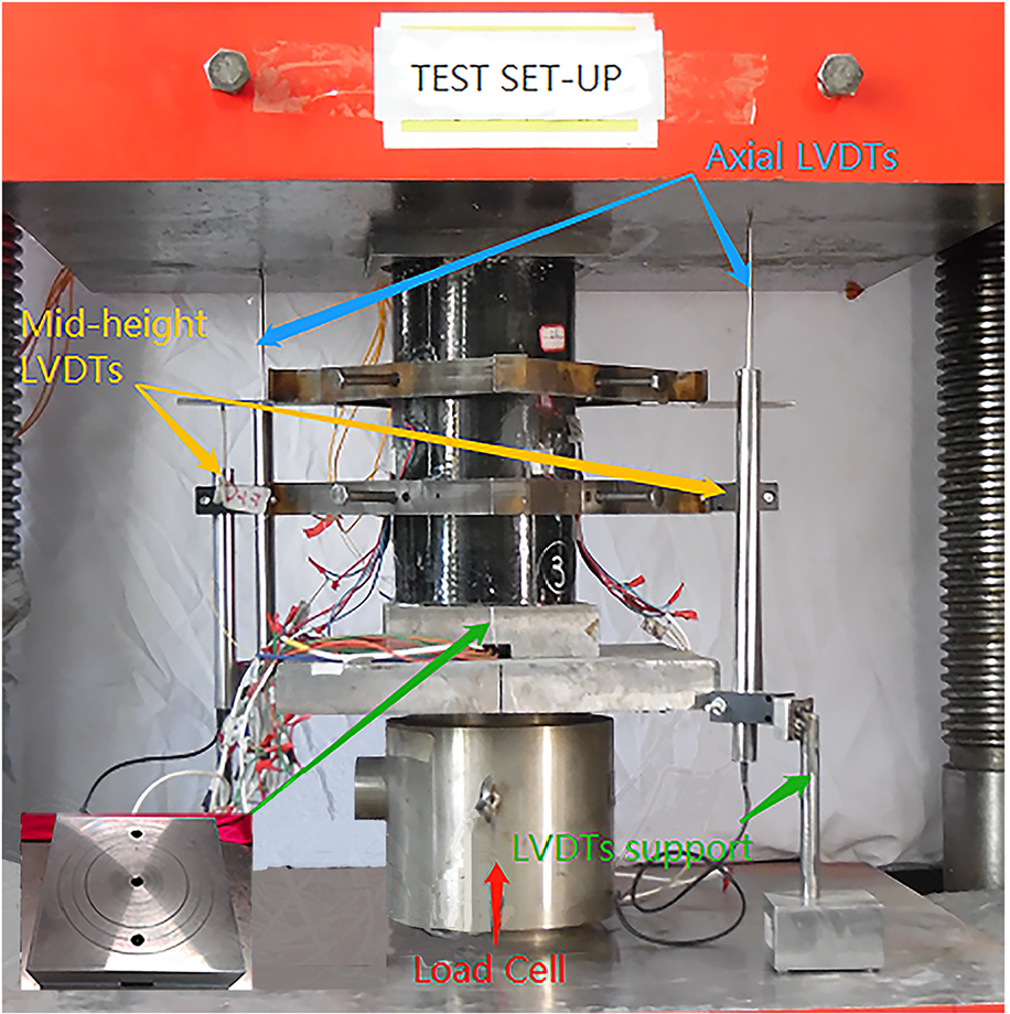
Test setup.
Test results
General behavior and failure mode
Generally, the hybrid DSTCs and BFST-DSTCs reached their maximum load at the rupture of the external FRP jacket. Figure 4 depicts the failure mechanism of a typical hybrid DSTC and BFST-DSTC. The hybrid DSTC failed abruptly at the rupture of the outer FRP tube with sudden drop in the load capacity. No strength recovery was noticed from the hybrid DSTC due to the high damage of the outer FRP tube (Figure 4(a)). The BFST-DSTCs showed a progressive failure mechanism that started by the gradual rupture of the outer FRP jacket (Figure 4(b)), accompanied by a slow decline of the axial load. The BFST-DSTC loosed its confinement force, and only the outer steel skin provided lateral pressure to the concrete. The initial fracture at the mid-height of the outer FRP extended toward both ends. The outer steel skin and outer FRP jacket debonded during the gradual descending (Figure 4(c)). The BFST-DSTCs failed at the rupture of the outer steel skin with obvious buckling deformation (Figure 4(d)). BFST-DSTCs exhibited good behavior compared with hybrid DSTC, especially at the post-peak stage. The use of the inner FRP steel allows the existence of a strength recovery for NSC specimens. BFST-DSTCs with GFRP showed brittle failure mechanism, whereas the specimens with BFRP are characterized by matrix-fiber cracking before the peak load.
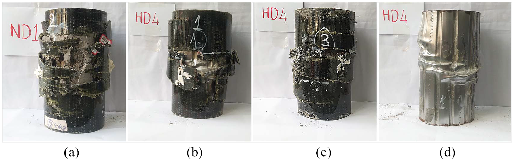
Failure mode of (a) hybrid DSTC and (b–d) BFST-DSTC.
Prior-peak performance
Axial load capacities
The load capacity defines the strength of the FRP-based confined concrete column at the prior-peak. The hybrid DSTCs and BFST-DSTCs reached their maximum load at the rupture of the FRP. Table 3 provides the experimental load capacities of the columns at the rupture of the FRP tube (Pf), the inner tube (Pinner), the outer tube (Pouter), and the unconfined concrete (Pco). Pinner and Pouter were obtained from the axial compressive test of hollow inner tube and outer tubes, respectively. Pco is the unconfined concrete strength (fco) times the concrete cross-section. The ratios
Axial load capacities of the columns at the rupture of the FRP and residual strength.

FRP: fiber-reinforced polymer.
Data obtained before outer FRP rupture occurred.
Not recorded.
Behavior of the concrete inside the hybrid DSTCs and BFST-DSTCs
The stress–strain curves of the confined concrete inside the FRP-based confined columns are critical to investigate. The concrete reached the maximum axial stress (fcc) at the rupture of the FRP jacket. The axial stress of the concrete in the hybrid DSTCs was determined based on the approach of Yu et al. (2010). The axial load supported by the outer steel was also deduced using the same method to calculate the stress of the concrete in BFST-DSTCs.
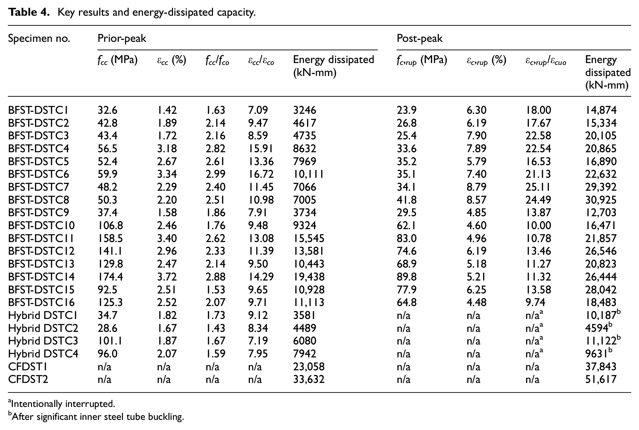
Figures 5 and 6 represent the stress–strain curves of the concrete inside the hybrid DSTCs and BFST-DSTCs with NSC and HSC, respectively. This section only discusses the stress–strain curves at the prior peak. Both hybrid DSTCs and BFST-DSTCs showed ascending piecewise linear segments before reaching fcc, which is commonly observed in the hybrid DSTC (Wong et al., 2008; Yu and Teng, 2010). The slopes of the segments of BFST-DSTCs are different from the hybrid DSTCs. The first elastic segment ends when the inner and outer steel tube yielded. The second segment starts after the outer and inner FRP jackets are fully active until the concrete reaches fcc. The BFST-DSTCs displayed a medium transition compared with the short transition of the hybrid DSTCs. Table 4 provides the fcc together with the corresponding compressive strain (εcc) of the confined concrete at the peak condition at the prior-peak. The rupture strain of the outer FRP jacket (εh, rup ) could be found in Table 3. The axial stress–hoop strain curves of BFST-DSTCs and hybrid DSTCs are also provided in Figures 5 and 6.

Stress-strain curves of NSC in (a-b) Hybrid DSTCs and (c-k) BFST-DSTCs.
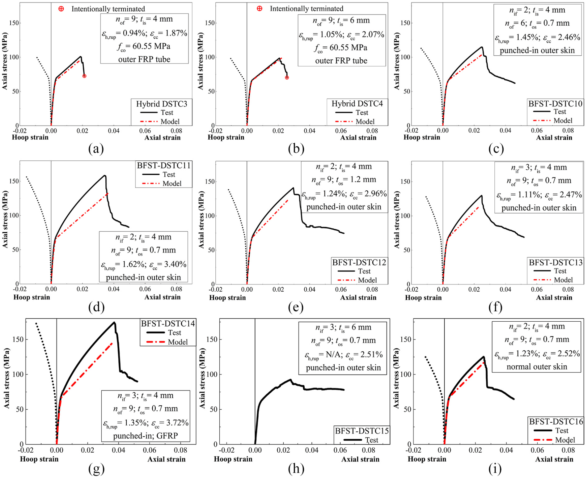
Stress-strain curves of HSC in (a-b) Hybrid DSTCs and (c-i) BFST-DSTCs.
Key results and energy-dissipated capacity.
Intentionally interrupted.
After significant inner steel tube buckling.
Buckling behavior of the inner tube
The inner tube deforms with the increase of axial stress. Figures 7 and 8 indicate the buckling process of the inner tube at each stage in the hybrid DSTCs and BFST-DSTCs, respectively. The subsequent images indicate that there is no buckling sign from the typical specimens by the rupture of the outer FRP jacket (point A). However, the specimen with three inner jackets (Figure 8(c)) exhibited high axial displacement prior to the failure of the outer jacket. The readings of the axial strain gages mounted on the inner steel tube indicated the high strain values of the hybrid DSTC when compared with the BFST-DSTCs.

Buckling mechanism of inner tube in hybrid DSTC with three basalt FRP layers (a) loading stage and (b) inner tube condition.

(a) Axial load-displacement. Buckling mechanism of inner tube BFST-DSTCs: (b) with two inner FRP layers and (c) with three inner FRP layers.
Ductility performance
The confinement ratio (εcc/εco), confinement effectiveness (fcc/fco), and the energy-dissipated capacity define the ductility performance of the column at the prior-peak. The curve OMF (Figure 9) stands for the simplified general stress–strain model for the ductility index calculation. The ductility indices at the prior-peak were evaluated from zero to the maximum load capacity (Figure 9(a)). The specimens reached their maximum load at point M, which indicates fcc (point A) and εcc (point B).
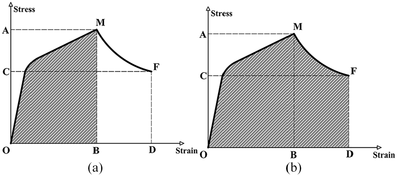
Simplified stress–strain curve for ductility and energy dissipated calculation (a) from 0 to maximum load and (b) from 0 to fracture point.
Table 4 recapitulates the εcc/εco, fcc/fco, and the energy-dissipated of the hybrid DSTCs and BFST-DSTCs. The energy-dissipated at the prior-peak is the area beneath the stress–strain plotted from O to M (Figure 9(a)). The energy-dissipated was calculated based on the load–displacement curves of the columns. Figures 10(a) and 11(a) represent the scattering energy-dissipated values for NSC and HSC, respectively. The green short-dashed line represents the average energy-dissipated by CFDST and hybrid DSTC for a same inner steel thickness. The gray dash-dotted line is the average of two hybrid DSTCs. Except for BFST-DSTC1 and BFST-DSTC9, the energy-dissipated by all BFST-DSTCs with NSC exceeded the average of the two hybrid DSTCs at M (Figure 10(a)). Unlike specimens with NSC, the BFST-DSTCs with HSC exhibited high energy-dissipated compared with the hybrid DSTCs at the prior-peak (Figure 11(a)). Furthermore, the normal BFST-DSTC with FRP-circular outer steel dissipated less energy compared with BFST-DSTCs made of FRP-punched-in outer tube.
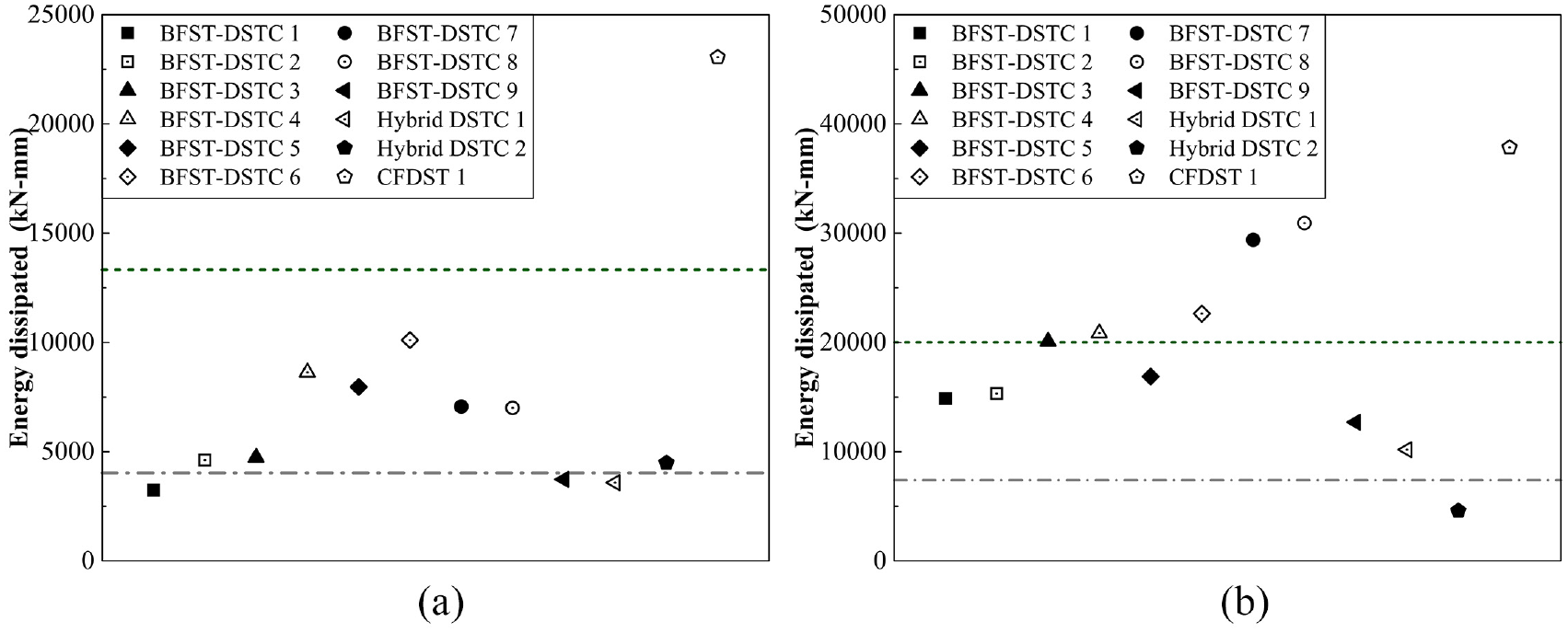
Energy dissipated of specimens with NSC: (a) from initial load to the maximum load capacity and (b) from initial load to the fracture point.
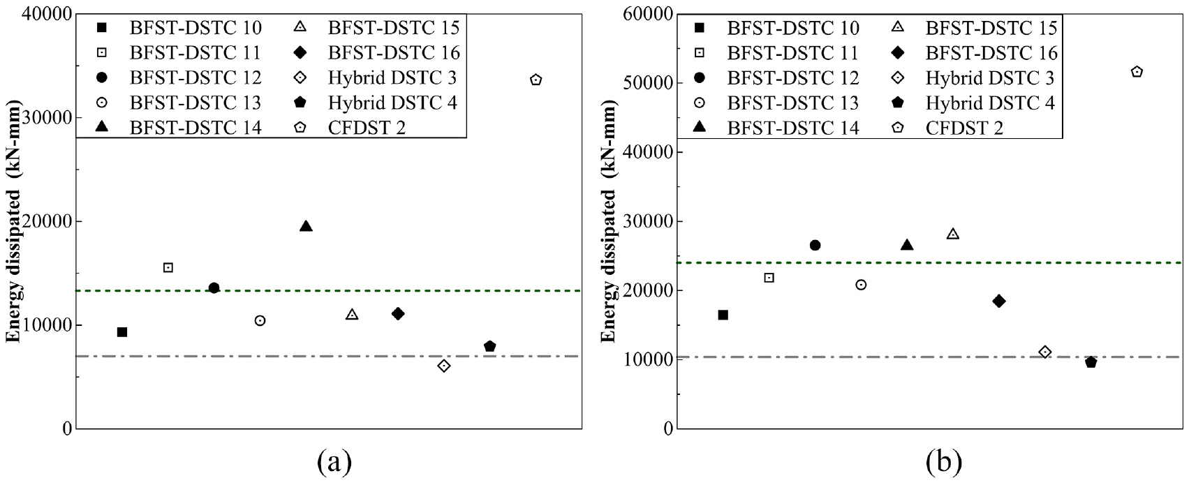
Energy dissipated of specimens with HSC: (a) from initial load to the maximum load capacity and (b) from initial load to the fracture point.
Post-peak performance
The BFST-DSTCs exhibited a post-peak behavior after reaching their maximum load capacity, whereas the hybrid DSTCs displayed sudden and continuous drop of the axial load.
Residual load
The BFST-DSTCs showed gradual decrease of the axial load, characterized by strength recovery for NSC specimens. The post-peak strengths depended on the inner tube configuration and the outer FRP steel tube confinement. Specimens with NSC had a second ascending peak load, whereas BFST-DSTCs with HSC displayed slow gradual descending. The rupture load (Prup) and the axial shortening (Srup) of BFST-DSTCs are provided in Table 3.
Behavior of the confined concrete
Figures 5 and 6 include the post-peak stress–strain curves of the confined concrete. The curve of hybrid DSTC2-4 was intentionally terminated because of obvious absence of post-peak strength. The BFST-DSTCs displayed better post-peak behavior, especially for specimens with NSC. The BFST-DSTCs exhibited a gradual descending section and a residual part that depends mainly on different parameters such as concrete strength, nature of the inner tube, and so on. Table 4 also recapitulates the post-peak rupture stress (fc, rup ) and strain (εc, rup ) of the concrete inside the BFST-DSTCs.
Buckling behavior of the inner tube
The inner tubes in hybrid DSTCs and BFST-DSTCs are under high-deformation at the post-peak. Figures 7 and 8 represent the inward buckling mechanism of the inner tubes in hybrid DSTCs and BFST-DSTCs, respectively. Note that the yellow marked numbers in the figures indicate the order of the inward buckling formation. Initial wrinkles (denoted by “0” in Figure 7) started to form in the inner tube of the hybrid DSTC at point B, just after the rupture of the outer FRP. BFST-DSTC2 has few wrinkles denoted by “1” (Figure 8(b)), whereas BFST-DSTC4 presents no wrinkles (Figure 8(c)). The hoop strain of the inner FRP jacket is also plotted in Figure 8(a). The initial crack between point A and B corresponds to the early inward buckling (i.e. wrinkles) of the inner steel (Figure 8(a)). The hoop strains of the BFST-DSTC4 were not included in the graph due to early damage of SGs wires. BFST-DSTC4 displayed buckling signs only near point C. The buckling deformation intensified when specimens reached their respective rupture load. The intensity of the inward buckling for specimens with more inner FRP layers is less intense at the final stage. Consequently, the inner FRP jackets control and limit the inward buckling at the prior and post peaks.
Ductility performance
The ductility performance at the post-peak depends on the confinement ratio (εc,rup/εcuo) and the total energy-dissipated by the column from the starting point (point O) to the initial fracture point (point F according to Figure 9(b)). For comparison, the hybrid DSTCs were loaded until intense buckling signs of the inner steel tube appeared. Table 4 provides εc,rup/εcuo and the total energy dissipated by the hybrid DSTCs and BFST-DSTCs. Figures 10 and 11 highlight the difference between the energy dissipated by specimens with NSC and HSC, respectively. Figures 10(b) and 11(b) show that the energies dissipated by BFST-DSTCs were higher compared with the results at the prior-peak. Table 4 demonstrates the significant enhancement in confinement ratio at the failure (εc,rup/εcuo) of BFST-DSTCs with NSC compared with HSC.
Discussion
Influence factor of inner FRP layer
The inner FRP jacket has been used in the experiment to enhance the mechanical behavior of the inner tube. Figure 12(a) highlights the effect of the inner jacket on the stress–strain behavior of the concrete inside the BFST-DSTCs. Specimen with three inner layers (BFST-DSTC4) displays high performance at the prior and post peaks. Table 4 confirms that BFST-DSTC4 had higher values compared with BST-DSTC2 in terms of fc, rup and εc, rup . The second ascending peak of NSC specimens was enhanced due to extra inner FRP layer. However, the uniform confinement ratio design limits the effect of the inner FRP layer in HSC specimens. The use of FRP steel had benefits on the overall performance of the BFST-DSTCs. Furthermore, the inner FRP jacket delays the damage and the inward buckling commonly observed in the hybrid DSTCs.
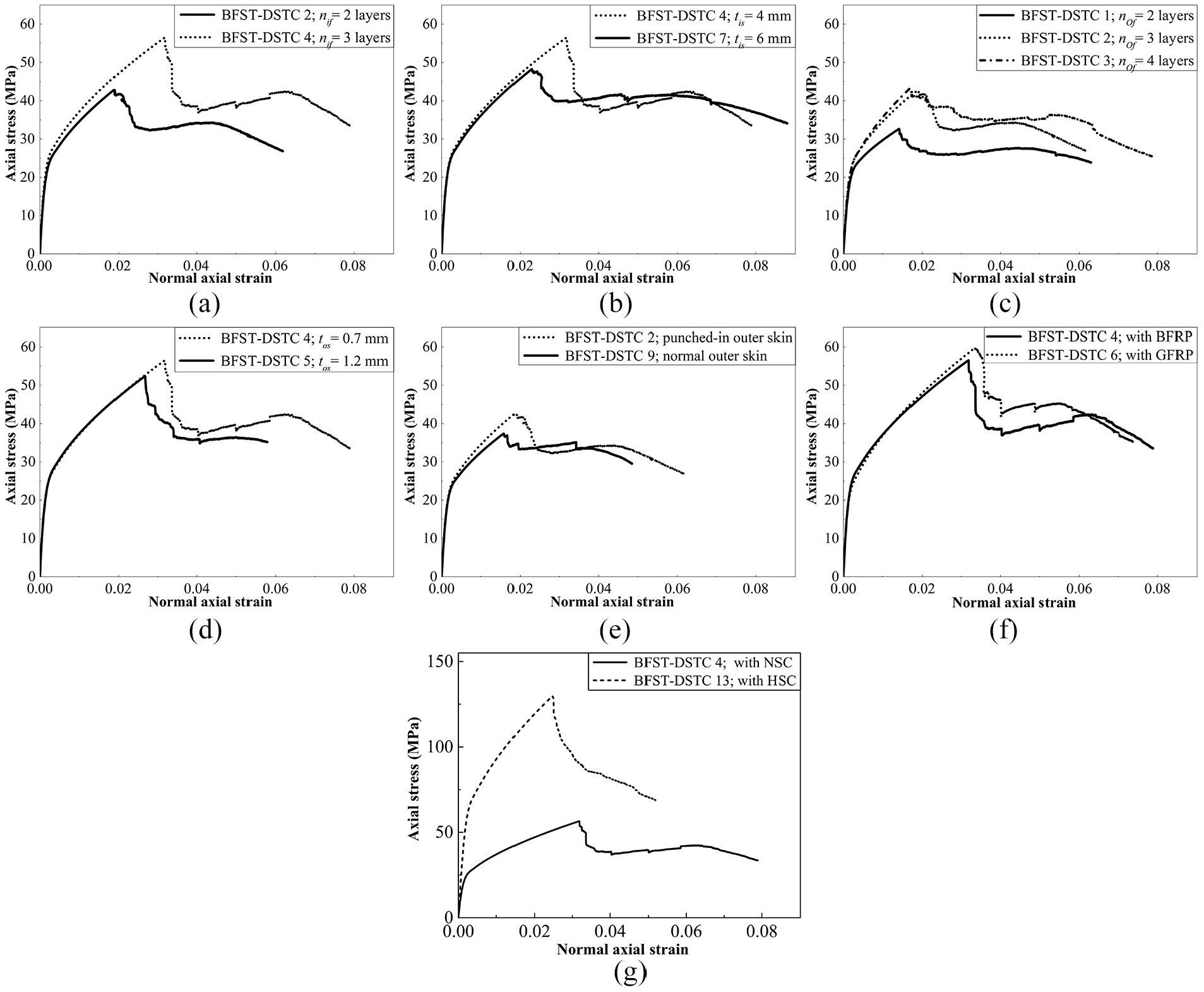
Influence factors on the stress–strain curves of confined concrete provided by (a) inner FRP jacket layers, (b) inner steel thickness, (c) outer FRP jacket layers, (d) outer steel skin thickness, (e) presence of punched-in pattern, (f) FRP type, and (g) concrete strength.
Influence factor of inner steel thickness
The steel thickness plays a critical role at the post-peak performance. Wong et al. (2008) and Louk Fanggi and Ozbakkaloglu (2013) have not found yet any concrete conclusion on the effect of the inner steel thickness, as both stated different closes. Figure 12(b) compares the axial stress–strain curves of BFST-DSTC4 and BFST-DSTC7. Specimen with 4-mm thickness displayed high fcc and εcc in prior-peak. The concrete inside the BFST-DSTC4 is well-confined compared with the BFST-DSTC7. However, the post-peak curves demonstrated the higher ductile response of specimen with a 6-mm inner steel compared with the 4-mm. Figure 10(b) (for NSC: BFST-DSTC4 and BFST-DSTC7) and Figure 11(b) (for HSC: BFST-DSTC13 and BFST-DSTC15) display additional explanation of this observation.
Influence factor of outer FRP layer
Previous studies demonstrate that the increase in the outer FRP thickness results in a significant enhancement of the load capacity and the ductility indices at the maximum compressive stress. Figure 12(c) distinguishes the stress–strain curves of concrete inside the specimens with two, three, and four outer FRP layers. Normally, BFST-DSTC3 with four (04) outer FRP layers should show higher values than BFST-DSTC2. However, the outer tube of BFST-DSTC3 had some manufacturing defects, which influence the actual stress–strain curve presented in Figure 12(c). The increase in confinement ratio resulted to considerable enhancement of the compressive strength. The outer FRP layer has influenced the stress–strain curves of the concrete at the post-peak.
Influence factor of outer steel skin thickness
The outer steel skin thickness controls the ductility in prior and post peaks. Figure 12(d) shows the stress–strain curves of BFST-DSTC4 (0.7 mm) and BFST-DSTC5 (1.2 mm). BFST-DSTC4 exhibited a high fcc and εcc in prior-peak. Specimen with 0.7 mm had efficient confinement compared with BFST-DSTC5. In addition, the stress–strain curves of BFST-DSTC4 showed enhanced second ascending section at the post-peak.
Influence factor of punched-in pattern of the outer steel skin
The main objective of the punched-in pattern is to enhance the confinement efficiency of the outer FRP. Figure 12(e) highlights the difference between the stress–strain curves of specimen with an outer FRP-punched-in steel skin (BFST-DSTC2) and FRP-circular steel skin (BFST-DSTC9). Both specimens have the same stiffness at the ascending bilinear segments. The specimen with punched-in outer steel skin displayed high fcc with enhanced εcc. These advantages are owing to the confinement effect from the outer jacket obtained by reducing the FRP steel contact surface (Huang et al., 2016). The axial load for the BFST-DSTC2 degraded slowly compared with the BFST-DSTC9 after loosing the outer FRP jacket confinement. However, BFST-DSTC2 has a high-energy dissipated capacity (Figure 10).
Influence factor of FRP type
The BFRP sheet enhanced the failure mechanism of the hybrid DSTCs and the BFST-DSTCs. Figure 12(f) provides the comparison between BFST-DSTC4 and BFST-DSTC6 with BFRP and GFRP, respectively. The specimen with GFRP displayed a higher fcc compared with the one made of BFRP. The excess can be attributed to the thickness of the fiber sheets (0.17 mm per layer for glass and 0.115 mm per layer for basalt). In term of weight, however, the specimen with basalt sheet is lighter than the one with glass, for the same configuration. Moreover, the specimen wrapped with BFRP sheet has reasonable value of εcc (Table 4). The performance of the specimens with BFRP is comparable with an advantage of being more ductile at the rupture. Furthermore, the basalt fiber is cost-effective and environmental friendly compared with the glass.
Effect of the concrete strength
The strength of the concrete core is the driving parameter that influences the overall performance of the confined system. Figure 12(g) shows the stress–strain curves of the concrete inside the BFST-DSTC4 (NSC) and BFST-DSTC13 (HSC). Obviously, BFST-DSTC13 had high fcc compared with BFST-DSTC4. Figures 10 and 11, as well as Table 4, reveal that the specimens with HSC display the highest energy-dissipated in both prior and post peaks. However, BFST-DSTC4 displayed higher εcc, same opinion from Ozbakkaloglu and Louk Fanggi (Louk Fanggi and Ozbakkaloglu, 2013; Ozbakkaloglu and Louk Fanggi, 2014) for the NSC specimens. The strain enhancement ratios at the specimen failure (εc,rup/εcuo) in Table 4 for BFST-DSTCs with NSC and HSC at the post-peak stage revealed the same opinion. Table 4 also demonstrates that the εc, rup of the BFST-DSTCs with NSC terminated away from the BFST-DSTCs with HSC.
Confinement model for the concrete inside the hybrid DSTCs and BFST-DSTCs
The design-oriented models (DOM) and the analysis-oriented models (AOMs) are the two types of relationship for confined concrete. The AOMs are generated by incremental numerical procedure, while the DOMs are obtained based on experimental results. This article adopted a DOM to predict the fcc and εcc of the BFST-DSTCs.
Comparison of test results and predictions from models
The models of Yu et al. (2010) and Huang et al. (2016) were used to predict the experimental results of the present study. The authors used a total of 55 hybrid DSTCs test database (Table 5), which were gathered from different existing researches (Louk Fanggi and Ozbakkaloglu, 2013; Ozbakkaloglu and Louk Fanggi, 2014; Teng et al., 2007; Wong et al., 2008; Zhang et al., 2017; Zhou et al., 2017). The details of the models used to predict the experimental results are available in the works conducted by Yu et al. (2010) and Huang et al. (2016). Statistic indicators were used to verify the accuracy and consistency of the models. The average absolute error (AAE), given by equation (2), defines the overall accuracy of the model. The mean (M), defined by equation (3), expresses the overestimation (M is greater than 1) or underestimation (M is less than 1) of the model. The standard deviation (SD), calculated by equation (4), establishes the magnitude of the associated scatter of the model



where avg is the average, n is the number of the dataset, exp is the experimental value, and mod is the prediction from the models.
Test database of hybrid DSTCs.

FRP: fiber-reinforced polymer; GFRP: glass fiber-reinforced polymer; CFRP: carbon fiber-reinforced polymer.
Do and H: diameter and height of the specimens.
Dimension in mm.
Figures 13(a) and (b) show the distribution of the strength enhancement ratio (fcc/fco) and strain enhancement ratio (εcc/εco) predicted by the models, respectively. The values of the statistic indicators were also provided in Figure 13. Huang et al.’s (2016) model provides inaccurate prediction of fcc and εcc for BFST-DSTCs. Both models calculated reasonably fcc of the hybrid DSTCs and BFST-DSTCs. However, Yu et al.’s (2010) model had less accuracy and underestimated fcc of BFST-DSTCs. Reasonable statistical indicators were observed when Yu et al.’s (2010) model predicts εcc of both hybrid DSTCs and BFST-DSTCs. Thus, Yu et al.’s (2010) model is employed as the basis of the proposed model to predict fcc and εcc of the concrete inside the hybrid DSTCs and BFST-DSTCs. The effect of the outer steel confinement should be considered to accurately predict the fcc of the BFST-DSTCs.
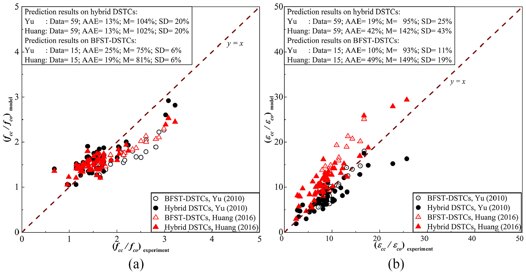
Experimental results versus existing models’ prediction of (a) strength enhancement ratio and (b) strain enhancement ratio.
New model for the BFST-DSTCs
The concrete inside the BFST-DSTCs is under lateral confinement force from both outer steel and outer FRP jacket. The evaluation conducted above shows that the steel confinement was omitted when using Yu et al.’s (2010) model to predict fcc of concrete inside the BFST-DSTCs. Thus, the equation originally proposed by Teng et al. (2009), defined in equation (5), is then modified

Without the effect of outer steel confinement,
Huang et al.’s (2016) model has considered the outer steel skin confinement effect, which should be also considered by Yu et al.’s (2010) model. Thus, the following expressions are proposed to predict the fcc of concrete inside the BFST-DSTCs

Where
The relationship between the confinement ratio (fl/fco),


fls is the confinement force from the outer steel skin, and
Assuming that fls is only active at the elastic stage, the equations (9) and (10) are given for fls and flf, respectively


with


The equation of Yu et al.’s (2010) model (equation (13)) does not consider the effect of the outer steel skin in the prediction of εcc.

Comparison of the proposed model and experimental results
The ultimate axial compressive strength and strain of concrete inside the BFST-DSTCs were calculated based on the proposed equations above. Figure 14 shows the predictions of equations (6) and (13) versus the experimental results of BFST-DSTCs. The AAE were below 10%, which is lower compared with the predictions from the models of Huang et al. (2016) and Yu et al. (2010). Moreover, equations (6) and (13) provided reliable estimation with less than 10% underestimation of fcc and εcc for the hybrid DSTCs and BFST-DSTCs. The axial stress–strain curves predicted by the proposed model are also plotted in Figures 5 and 6. The curves were obtained based on the stress–strain relationship of a DOM for FRP-confined concrete, originally presented by Lam and Teng (2003). The predictions are in good agreement with the experimental results. However, an AOM should be developed to predict accurately the behavior of the concrete inside the BFST-DSTCs.
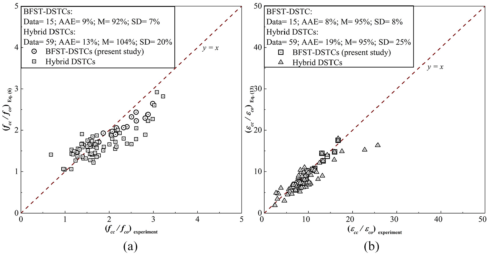
Proposed equations versus experimental results (a) equation (6) and (b) equation (13).
Conclusion
Prior and post peaks axial compressive behavior of the novel form of DSTCs with an outer FRP-punched-in steel and inner FRP-circular steel tubes have been investigated in this article. The experimental results draw the following findings:
The BFST-DSTC exhibits the best performance in terms of load capacity, confinement ratio, failure mechanism, ductility, and energy-dissipated capacity at the rupture of the outer jacket without reaching its ultimate deformation;
The axial stress–strain curves of the concrete inside the BFST-DSTCs include (a) ascending piecewise linear segments characterized by two yield points, a medium transition section, and the rupture point of the outer FRP jacket; (b) a gradual descending section after the initial rupture of the outer jacket; and (c) an enhanced post-peak. Strength recovery with a noticeable second ascending peak distinguishes the post-peak branch for BFST-DSTCs with NSC, which depends on the inner tube design;
The introduction of the inner jacket delays the buckling mechanism of the internal tube, thus improving the load-bearing capacity at yield and peak stages. The thickness of the inner FRP jacket governs the post-peak performance of the BFST-DSTCs. The obtainment of the optimal thickness should consider the inward buckling deformation of the steel tube;
The presence of the punched-in patterns in the outer steel skin solves the confinement efficiency issue of the outer jacket. As a result, the prior and post peaks show an increase in the load capacity with high-energy dissipated capacity. The addition of BFRP improves the ductile damage mechanism of the proposed system;
A good post-peak with high-energy dissipation capacity illustrates the unique feature of the BFST-DSTCs. The BFST-DSTC system is able to prevent the total collapse of the concerned structure when the rupture of the FRP jacket occurred;
The equation proposed to predict the compressive strength of the concrete inside the BFST-DSTC provides satisfactory prediction.
Further investigation on the BFRP-steel bonding behavior in both inner and outer composite tubes is necessary for deeper understanding on the damage mechanism of the BFST-DSTC. Finally, a more detailed new analysis-oriented axial stress–strain model should be considered to obtain an accurate prediction of the mechanical behavior of the BFST-DSTC before and after the rupture of the outer FRP jacket.
Footnotes
Acknowledgements
The authors are grateful to all bachelors’ students, colleagues, and friends for their support and contribution to the realization of the experiment. The first author acknowledges all the supports and love from his relatives.
Declaration of Conflicting Interests
The author(s) declared no potential conflicts of interest with respect to the research, authorship, and/or publication of this article.
Funding
The author(s) disclosed receipt of the following financial support for the research, authorship, and/or publication of this article: The authors appreciate enormously the financial support received from the National Key R&D Program of China (Project ID: 2017YFC0703008) and the research funding from the “Hainan University, Sichuang QianYi Composite Materials Co., Ltd. and HuaYing Government” Engineering Center for Basalt Fiber Application.
