
Abstract
A novel shaking table substructure testing method that includes interaction forces determined by actuator forces and shaking table dynamic parameters is proposed and validated. The seismic performance of a storage tank that incorporates soil-structure interactions is investigated by the method proposed in this article. The experimental results show that the proposed shaking table substructure testing method is an efficient alternative method of evaluating the seismic performance of a storage tank that incorporates soil-structure interactions. The experimental results show that the influence of the soil-structure interactions increases as the stiffness of the foundation soil decreases, which was demonstrated by the results showing that the displacement and acceleration responses of the storage tank decrease as the stiffness of the foundation soil decreases. Moreover, the influence of the soil-structure interactions increases as the liquid height increases, which was illustrated by the decreased displacement responses of the storage tank with increases in the liquid height. The maximum acceleration response of the storage tank occurred at the liquid surface height.
Keywords
Introduction
With the rapid development of the petroleum and petrochemical industries in recent decades, storage tanks have increasingly been used. These tanks normally contain large volumes of flammable hazardous chemicals, and a small accident may lead to million-dollar property losses and production interruptions over a number of days, whereas a large accident may result in human casualties, stock devaluation, or company bankruptcy (Chang and Lin, 2006). During an earthquake, storage tank accidents are more serious if the tank is damaged or collapses. Therefore, the seismic performance of storage tanks should be investigated and the results should be applied to the design process.
The seismic performance of storage tanks is primarily investigated by the following four methods: theoretical analyses as shown by Hoskins and Jacobsen (1934), Veletsos (1977), Azzuni and Guzey (2015), and Larkin (2008); numerical simulations as conducted by Rondon and Guzey (2016), Ormeño et al. (2015b), and Mandal and Maity (2015); model experiments as shown by Haroun (1983), Ormeño et al. (2015a, 2015c); and post-earthquake investigations (Brunesi et al., 2015). Model experiments play the most important role compared with the other methods. The seismic performance of a storage tank can be investigated by traditional shaking table testing in which the entire structure is chosen as the specimen, which means that the traditional shaking table testing method can only complete small-scale storage tank model experiments. However, the performance of the foundation soil and the storage tank with liquid are so complicated that the small-scale experiments are difficult to satisfy the laws of similitude. Therefore, the experimental results of traditional shaking table tests cannot easily reveal the seismic performance of the corresponding practical storage tank when considering the properties of soil. This article proposes a novel shaking table substructure testing method that aims to accurately evaluate the seismic performance of storage tanks by considering soil-structure interactions (SSIs) with large-scale models at low cost.
Real-time pseudo dynamic testing was proposed by Nakashima et al. (1992). Since then, the method has been investigated, progressed, and applied to several practical engineering structures. This idea was expanded to shaking table substructure testing (Horiuchi et al., 2000) and further developed in the last decade as shown in Lee et al. (2007a, 2007b), Igarashi et al. (2008), Ji et al. (2009), Shao et al. (2011), Wang et al. (2016), Zhang et al. (2016). When conducting shaking table substructure tests, the target structure is normally divided into a numerical substructure and an experimental substructure. The numerical substructure is numerically simulated using a computer, the experimental substructure is then loaded by a shaking table, and the corresponding interaction force between the shaking table and specimen is measured and fed back to the step-by-step integration algorithm in the numerical substructure to calculate the following integration time steps.
Considerable research progress has been made in recent years on the shaking table substructure testing method; however, the investigations have mostly focused on high-accuracy integration algorithms and loading control methods, and few researchers have focused on the mechanism of the shaking table testing to improve its experimental accuracy. The effective interaction force as a key value of the shaking table test should be assessed to improve the experimental accuracy of the method. Otherwise, the measured errors in the interaction force may accumulate step-by-step, which may adversely influence the accuracy or even the stability of the experimental results. Moreover, the shaking table substructure tests have mostly been validated by small-scale specimen tests with simplified models. The method is highly desirable for evaluating the seismic performance of large-scale practical engineering structures.
In this study, a novel shaking table substructure testing method that includes the interaction force calculated by actuator forces and shaking table dynamic parameters is proposed and validated, and the method is then applied to investigate the seismic performance of a large-scale storage tank incorporating SSIs. The focus of this study is the influence of foundation soils and liquid heights on the displacement and acceleration responses of the storage tank; therefore, the storage tank with liquid is chosen as the experimental substructure and the foundation soils is calculated by one simplified model in order to realize real-time substructure tests. The simplified model analysis of a storage tank that incorporates SSIs is introduced in section “Simplified model analysis of storage tank considering SSI.” The shaking table substructure testing method with calculated interaction force based on model updating of the shaking table is proposed and validated in sections “Shaking table substructure test method with calculated interaction force” and “Experimental validation of the shaking table substructure test method.” The influence of foundation soils and liquid heights on the displacement and acceleration responses of the storage tank is investigated by the proposed method in section “Experimental results analysis of the storage tank considering the SSI,” and the main conclusions are summarized in section “Conclusion.”
Simplified model analysis of storage tank considering SSI
Simplified models and parameters of soil foundations for time domain dynamic analyses have been widely investigated by Wolf and Somaini (1986), Jean et al. (1990), Luan and Lin (1996). In this study, a two-degrees-of-freedom (2-DOF) mechanical model with eight constant lumped parameters, which is similar to the models proposed by Wolf and Somaini (1986), Jean et al. (1990), Luan and Lin (1996), was applied to simulate the dynamic performance of foundation soil. To clarify the findings, a storage tank with liquid is simplified as a 1-DOF mass–damping–stiffness system. The 3-DOF lumped parameter model of a storage tank considering the effect of SSIs is shown in Figure 1.
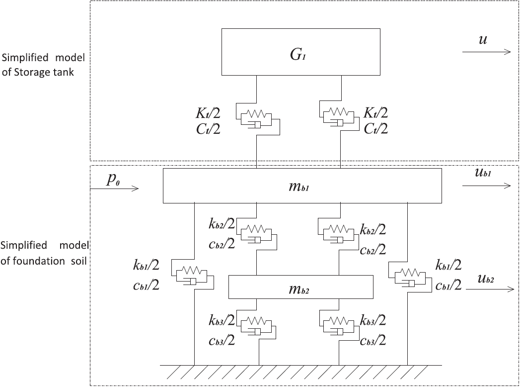
Simplified model of the storage tank incorporating SSIs.
The motion of a storage tank with liquid can be estimated by equation (1), and the corresponding interface shear force between the storage tank and boundary soil can be expressed as equation (2)


where u is the displacement response of liquid inside the storage tank corresponding to the foundation displacement

where
The equation of motion for the foundation soil can be expressed as follows

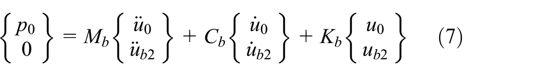
where Mb, Cb, and Kb are the mass, damping, and stiffness matrix of the boundary soil, respectively; and Ub and F are the displacement response and external force, respectively. These terms can be expressed as follows

where p0 is the equivalent excitation force of an earthquake wave; ub1 and ub2 are the displacement responses of the masses mb1 and mb2 of the foundation soil model, respectively. The terms mb, kb, and cb can be calculated as follows
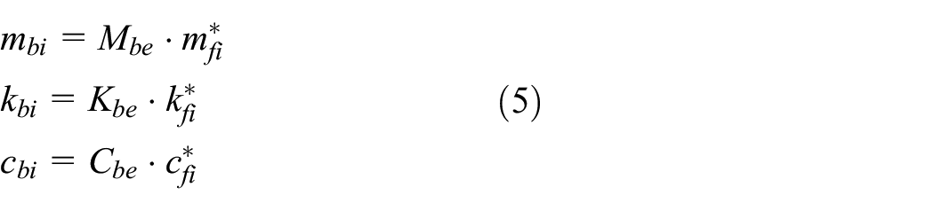
where subscript i equals 1 or 2. Mbe, Kbe, Cbe are the equivalent mass, stiffness, and damping, respectively, and they can be determined for a strip foundation as follows

where
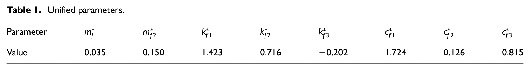
Unified parameters.
The equivalent excitation force p0 can be determined by the following equation
where u0 is the measured earthquake displacements on foundation mb1.
Shaking table substructure test method with calculated interaction force
Shaking table substructure test methodology
In this study, foundation soil was selected as the numerical substructure and simulated using a computer, and the storage tank with liquid was selected as the experimental substructure and tested on the shaking table as shown in Figure 2. The two substructures coordinate on their boundary in terms of the displacement ub1 and the shear force T. The equivalent excitation force p0 on the interface of the two substructures is determined by equation (7) using the measured earthquake foundation displacement responses. Equation (4) is used to calculate the displacement response of the 2-DOF lumped model of dynamic impedances of foundation soil with the measured interface shear force T and the equivalent excitation force p0. The displacement ub1 is the excitation displacement of the experimental substructure and can be realized with the shaking table. The corresponding interface shear force T is measured and feeds back to the numerical substructure to calculate the further steps.

Shaking table substructure test of the storage tank incorporating SSIs.
Step-by-step integration algorithm
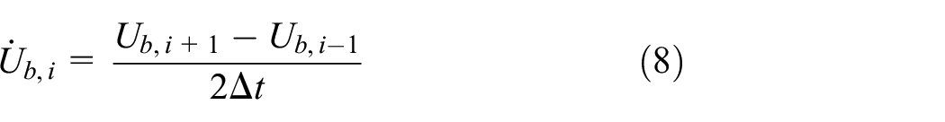
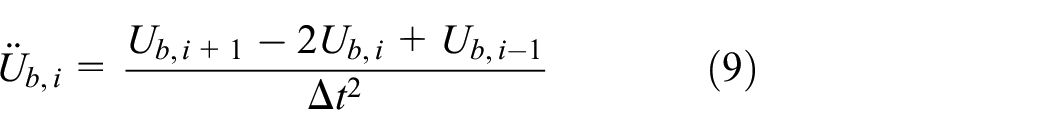
The central difference method for real-time substructure testing proposed by Wu et al. (2009) was used to solve the discretized equation of motion of numerical substructure as shown in equation (4). The velocity and acceleration approximations of the central difference method are as follows
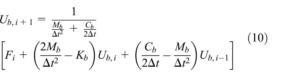
By substituting equations (8) and (9) into the discretized equation (4) at the ith step, one can obtain the following
For an actuator controlled with a traditional displacement mode, the achievement of the explicit velocity or acceleration target depends on how the displacement command is issued with respect to time. To this end, we assumed a constant acceleration in the time interval from ti to ti + 1, which resulted in a displacement command profile as a quadratic function in time
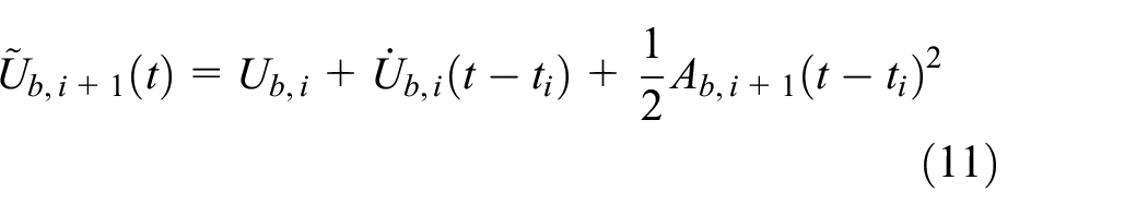
in which
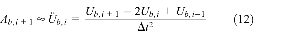
Figure 3 shows the flow chart of the shaking table substructure test for a storage tank incorporating SSIs with the central difference method.
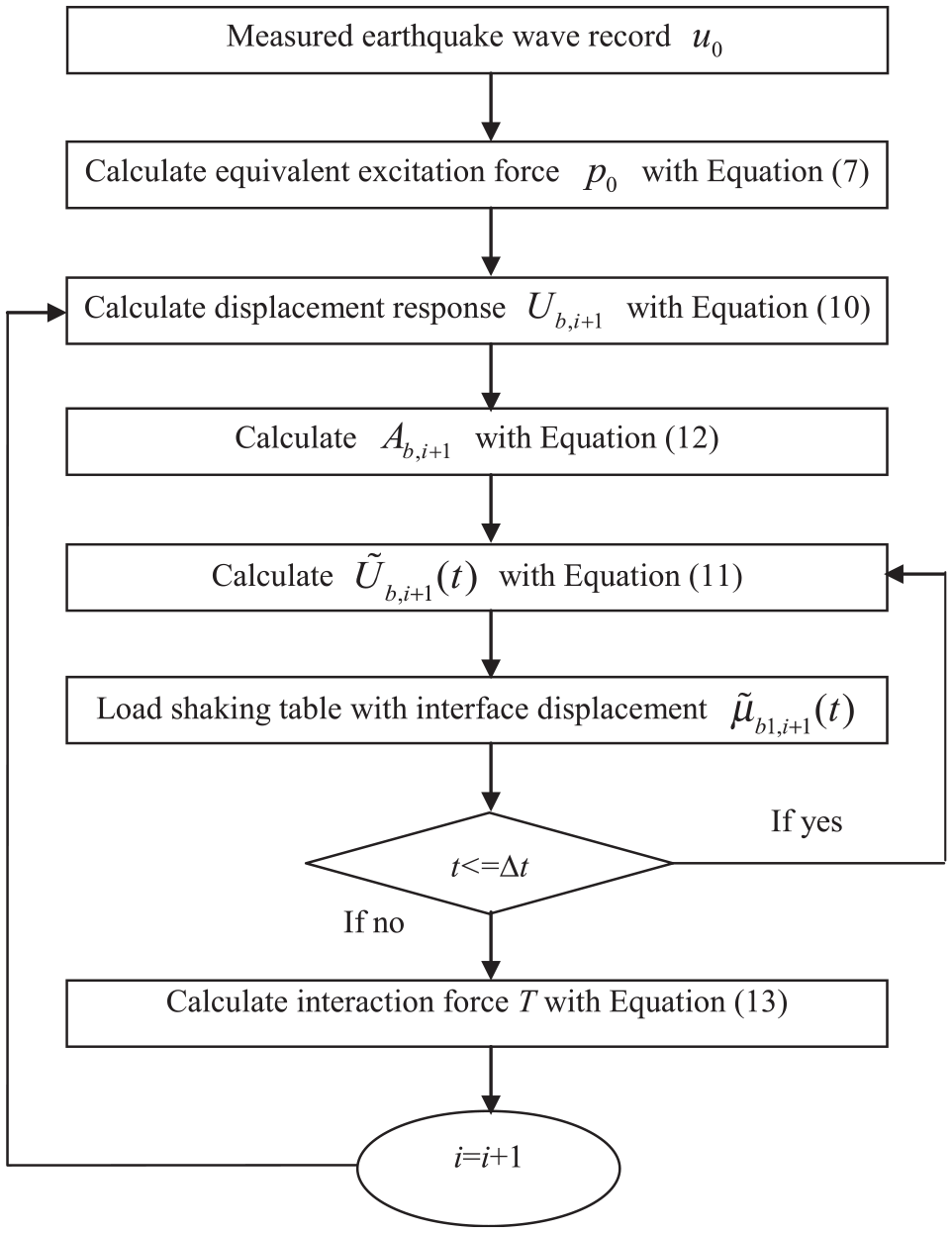
Flow chart of the shaking table substructure testing method.
Interface force calculation method based on model updating
When conducting the shaking table substructure test, the foundation soil was simulated using a computer and the storage tank with liquid was tested on the shaking table. For the numerical substructure, the parameters of the foundation soil listed in Table 1 were considered in the tests, and the corresponding calculation process presented in Figure 3 was adopted. The corresponding interface shear force T should be measured and fed back to the numerical substructure to calculate further steps. In this study, the shaking table was simplified as a mass–stiffness–damping system; with the measured force FA from the force transducer inside the actuator, the interface shear force T could be estimated as follows

where
The steel plate of the shaking table occupies the majority mass on the ground level. The shaking table of Harbin Institute of Technology specifically designed to move only in one direction, so the shaking table without model constructed on it can be taken as a single degree-of-freedom (SDOF) system. An accurate model of the shaking table would greatly contribute to the implementation of the proposed substructure tests, and the overloaded application of the shaking table may change its parameters. The geometric nonlinearity of the shaking table system can be ignored when the displacement of the shaking table is very small. Overloading protection of the shaking table is adopted to limit the displacement and acceleration of the testing system. In this case, the stiffness of the shaking table system and mass remains as constant during the testing. There is no additional damper added to this system; therefore, Rayleigh damping assumption is adopted. And the damping also remains constant in this process. Therefore, the parameters had to be identified before the implementation of the substructure test. In this section, an identification method based on an extended Kalman filter (EKF) used for the identification of the damping and stiffness of the shaking table is explained. The mass of the shaking table was calculated according to the design drawings and taken as a constant. The comparison of the calculated acceleration and measured acceleration is shown in Figure 4.

The comparison of the estimated and the measured acceleration of shaking table.
For the structural parameter identification with a reduced EKF, a discrete state equation is expressed as equation (14) and an observation equation can be expressed as equation (15) with a reduced EKF

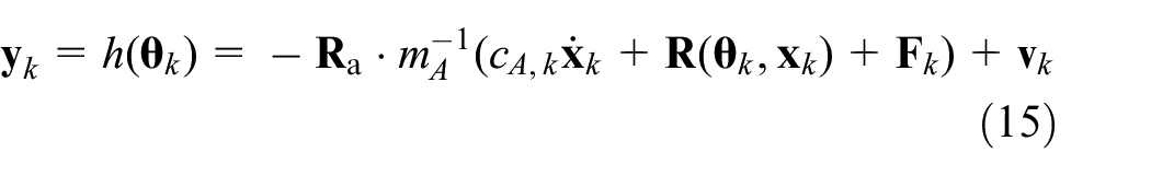
where mA and cA represent the mass and damping of the shaking table.
Experimental validation of the shaking table substructure test method
Experimental setup
One steel storage tank was used as the specimen. The dimension of the connection board is 2.01 m × 2.2 m × 0.005 m, and the height, radius, and the thickness are 1.6, 1, and 0.001 m, respectively. The experimental setup of the storage tank is shown in Figure 5, and the test picture is shown in Figure 6. The connection board of the storage tank is anchored on the shaking table with bolts.

Experimental setup of the storage tank (unit: mm): (a) storage tank configuration and (b) top view of the storage tank and shaking table.
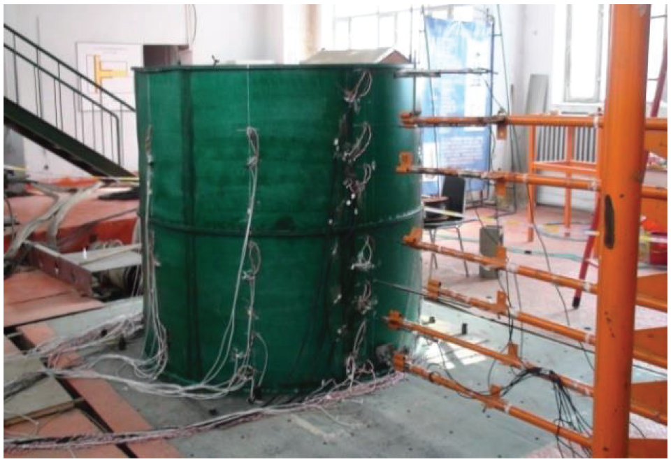
Test picture of the storage tank on the shaking table.
Five displacement transducers and five acceleration transducers were installed on the storage tank during the tests as shown in Figure 7. The acceleration transducers are numbered A1–A5, and the displacement transducers are numbered D1–D5 from the bottom to the top of the storage tank.
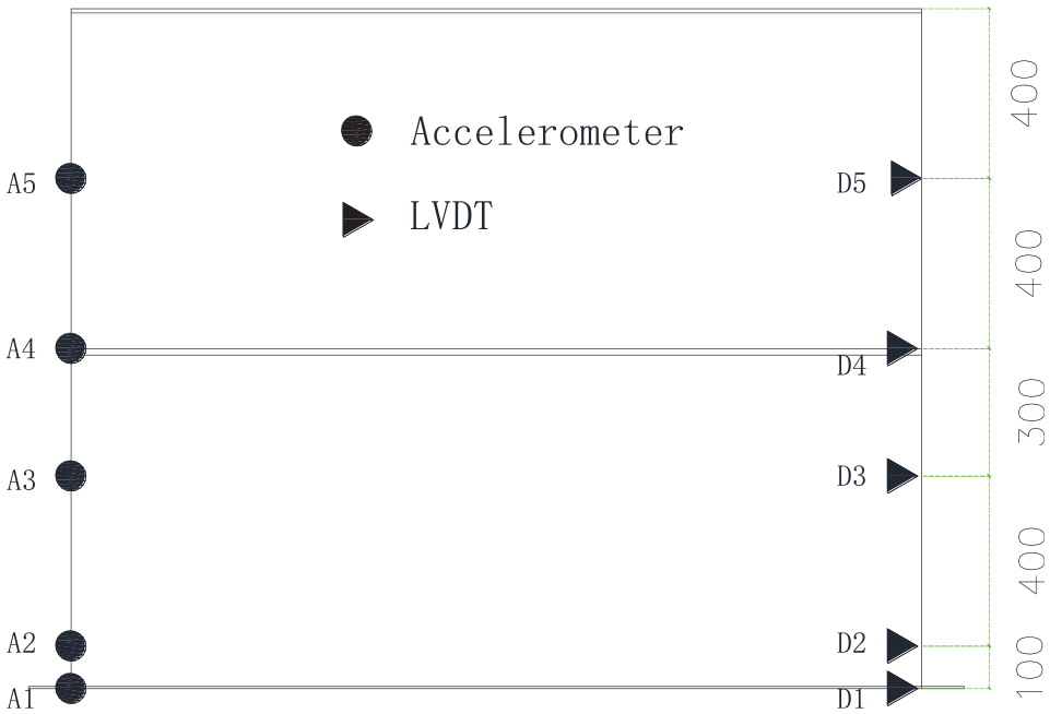
Transducers on the storage tank (unit: mm).
The tests were conducted at the Structural and Seismic Testing Center of the Harbin Institute of Technology. The shaking table was used as the loading facility, and the actuator was controlled using the displacement feedback control strategy. MTS 793.10 software, MTS Systems (China) Co., Ltd., was used as the corresponding control system, and the Calculation Editor block of this software can perform real-time calculations of the numerical substructure as shown in equations (10)–(12).
Experiment results analysis
In the shaking table substructure testing, three types of foundation stiffness were considered: fixed, hard, and soft. The fixed foundation denotes the condition in which the experimental results are only determined by the seismic responses of the storage tank without the effect of SSIs, and hard and soft foundations denote the condition in which the experimental results correspond to the seismic responses of the storage tank incorporating the SSIs. In the following sections, the shear wave velocity
The comparison between the displacement command and response is shown in Figure 8. Figure 8 presents the displacement response of the shaking table substructure testing subject to Taft earthquake ground motion with a PGA of 105 gal and a liquid height of 0 cm with soft foundation. This case evaluates the foundation displacement movements excited by the earthquake excitation without the influence of the storage tank. It is shown from the figure that the displacement response soft foundation well matched the corresponding displacement commands sent by the testing system. The results of other two cases as the fix foundation and hard foundation are the same effect but not listed due to the limited length of the article. In this experimental study, the corresponding interface shear forces (T, calculated with the measured responses as shown in equation (13)) were nearly zero, which is consistent with the experimental case of a storage tank without liquid. The results demonstrated that the interaction force was correctly evaluated using equation (13) with identified model parameter values of the shaking table. The displacement response of the shaking table is very close to the displacement command which illustrates that the shaking table is well controlled with the control system.
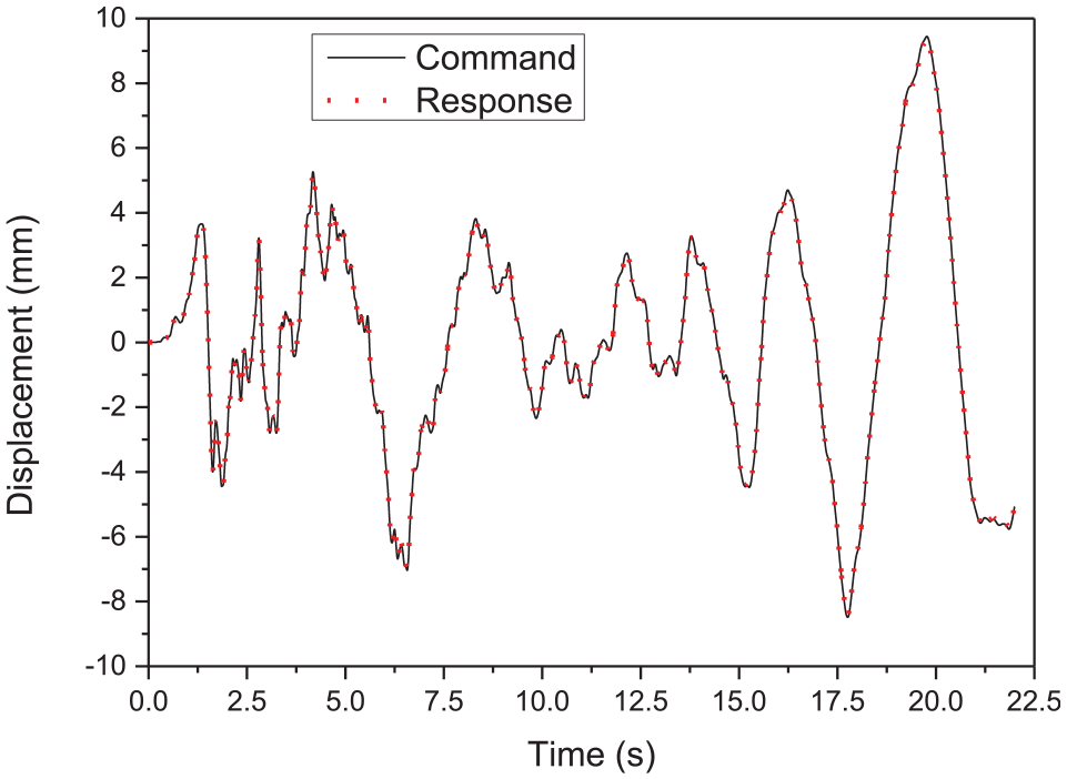
Displacement responses of the storage tank without liquid (soft foundation).
Experimental results analysis of the storage tank considering the SSI
Experimental results
Displacement responses
The displacement responses of the storage tank subject to Taft earthquake ground motion records with liquid heights of 120 cm are shown in Figure 9. The peak value of the displacement in other cases as the heights of 50 and 80 cm are listed in Table 2. The PGA of the Taft earthquake ground motion records was 105 gal. The displacement responses corresponding to different positions on the storage tank are shown from D1 to D5.
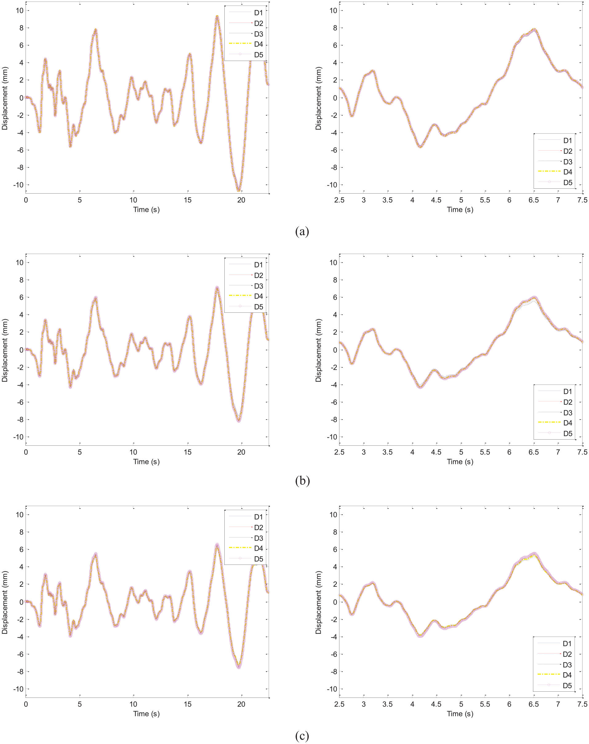
Displacement responses of the storage tank with a 120-cm liquid height: (a) fixed foundation, (b) hard foundation, and (c) soft foundation.
Peak values of the displacement response (mm).

Acceleration responses
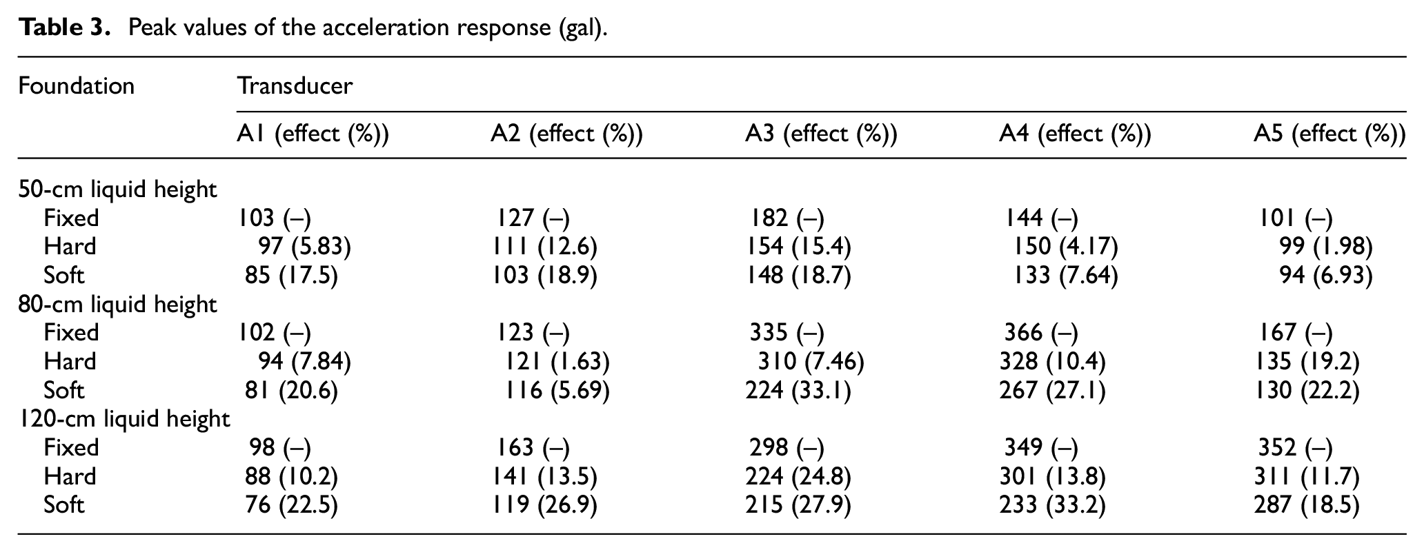
The acceleration responses of the storage tank subject to Taft earthquake excitation with liquid heights of 120 cm are shown in Figure 10. The PGA of the Taft earthquake ground motion records was 105 gal. The acceleration responses corresponding to different position on the storage tank are shown from A1 to A5. The peak value of the acceleration in study cases of the heights of 50 and 80 cm is listed in Table 3.
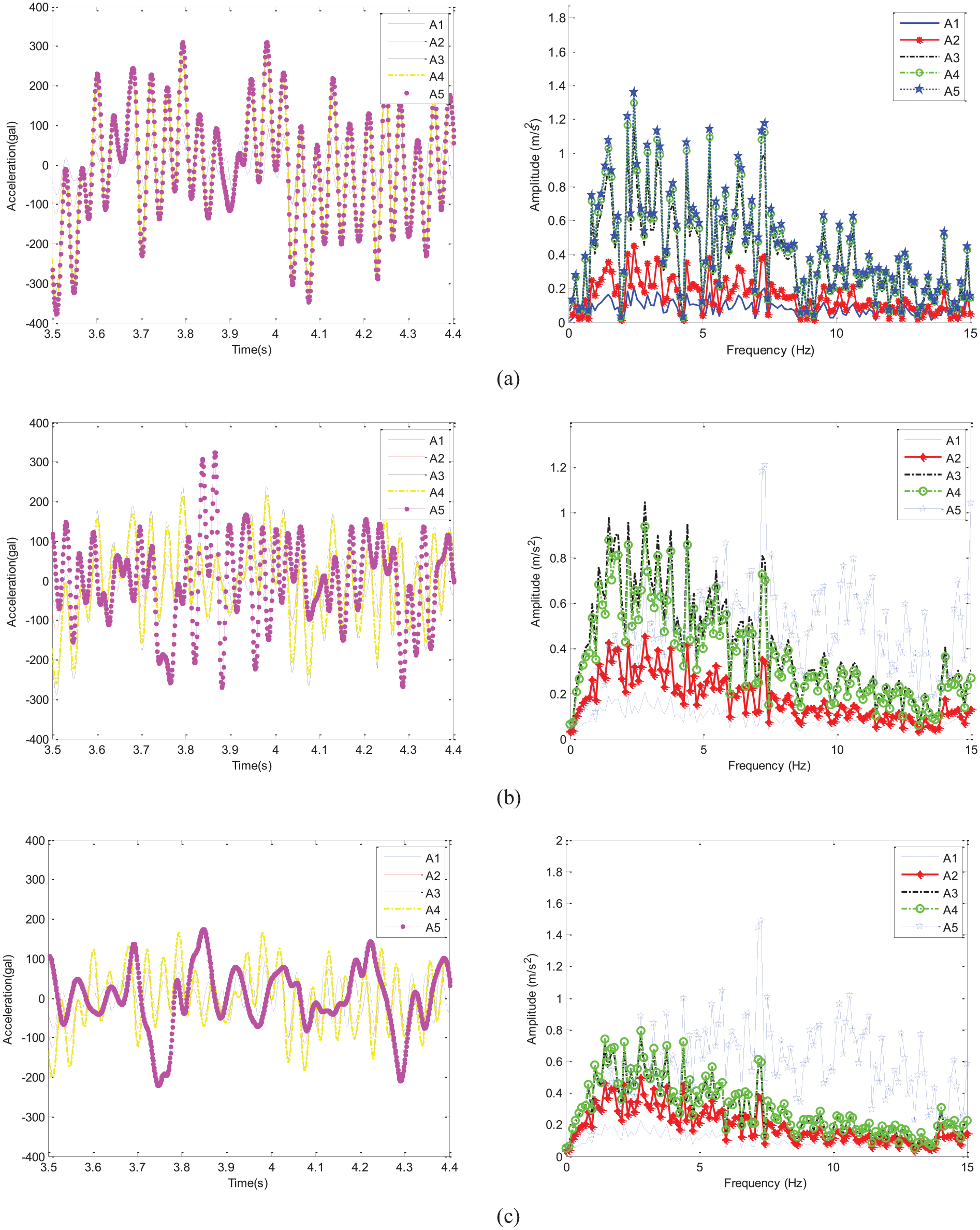
Acceleration responses of the storage tank with a 120-cm liquid height: (a) fixed foundation, (b) hard foundation, and (c) soft foundation.
Peak values of the acceleration response (gal).
Influence analysis of foundation soils
Displacement response analysis
The peak values of the displacement responses from D1 to D5 corresponding to different liquid heights are listed in Table 2. The tables show that the differences of the displacement response peak values from D1 to D5 were negligible and the average peak values decreased with the decrease in foundation soil stiffness. The displacement responses decreased by 7.8%, 11.7%, and 19.2% on the hard foundation compared with those on the fixed foundation for the storage tank with liquid heights of 50, 80, and 120 cm, respectively. In addition, the displacement responses decreased by 16.7%, 24.3%, and 30.8% on the soft foundation compared with those on the fixed foundation for the storage tank with liquid heights of 50, 80, and 120 cm, respectively. The results indicated that the displacement responses decreased based on the contribution of the SSIs and showed that the influence of the SSIs increased as the stiffness of the foundation soil decreased. The same conclusions were reached from the El Centro earthquake ground motion record input tests.
Acceleration response analysis
The peak values of the acceleration response subjected to the Taft earthquake ground motion records for storage tanks with liquid heights of 50, 80, and 120 cm are listed in Table 3, respectively. The acceleration response peak values decreased up to 15.4%, 19.2%, and 24.8% on the hard foundation compared with those on the fixed foundation for the storage tank with liquid heights of 50, 80, and 120 cm, respectively. In addition, the acceleration responses decreased up to 18.9%, 33.1%, and 33.2% on the soft foundation compared with those on the fixed foundation for the storage tank with liquid heights of 50, 80, and 120 cm, respectively. That means the acceleration response peak values from A1 to A5 decreased as the stiffness of the foundation soil decreased. The acceleration response peak values on fixed, hard, and soft foundations corresponding to 50-, 80-, and 120-m liquid height occurred on A3, A4, and A5, respectively. The results showed that the influence of the SSI increased as the stiffness of the foundation soil decreased and the maximum acceleration response of the storage tank on fixed, hard, and soft foundations occurred at the same liquid surface height. The same conclusions were reached from the El Centro earthquake ground motion record input tests.
Influence analysis of liquid heights
Displacement response analysis
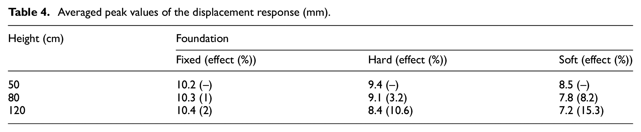
The peak values averaged over D1–D5 with respect to different liquid heights and foundation soils are listed in Table 4. Table 4 shows that on the fixed foundation, the differences of the displacement response averaged peak values for liquid heights of 50, 80, and 120 cm were negligible, whereas on the hard foundation, the averaged peak values decreased by 3.2% and 10.6% for liquid heights of 80 and 120 cm, respectively, compared with a liquid height of 50 cm; and on the soft foundation, the averaged peak values decreased by 8.2% and 15.3% for liquid heights of 80 and 120 cm, respectively, compared with a liquid height of 50 cm. These results indicate that the influence of the SSIs increased with the increase in liquid height on the hard and soft foundations.
Averaged peak values of the displacement response (mm).
Acceleration response analysis
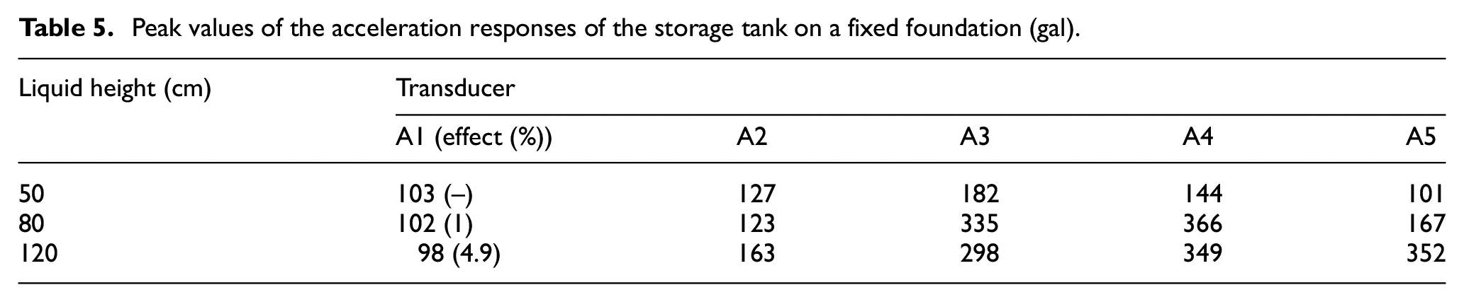
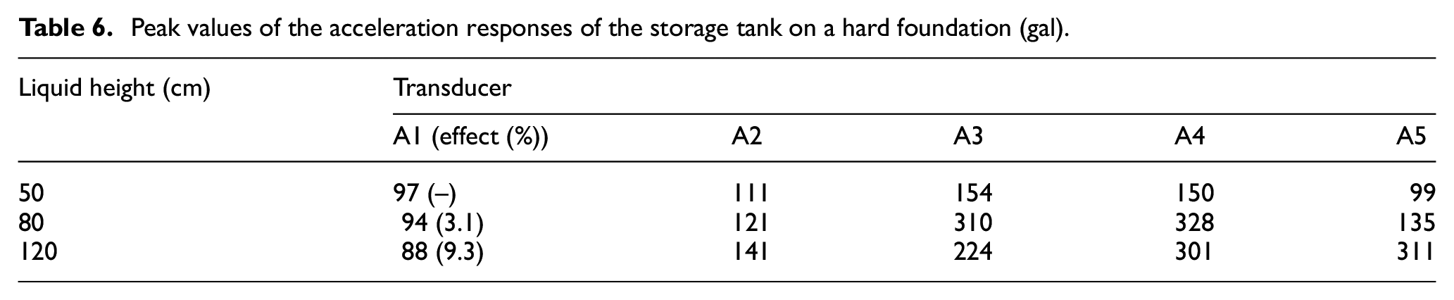
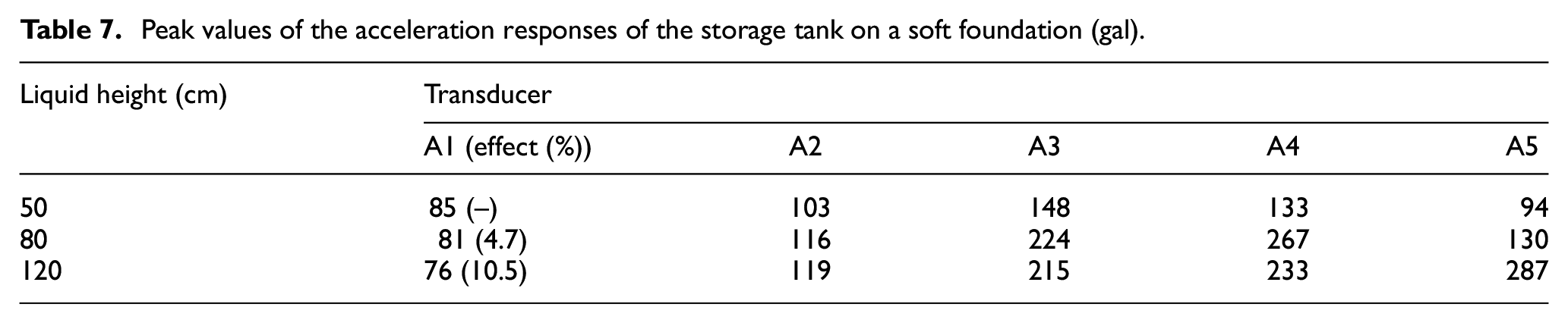
The acceleration response peak values with liquid heights of 50, 80, and 120 cm on the fixed, hard, and soft foundations are listed in Tables 5 to 7, respectively. The tables show that the peak values of A1 on fixed, hard, and soft foundations decreased as the liquid height increased. With a 50-cm liquid height on fixed, hard, and soft foundations, the peak values of the acceleration responses increased from A1 to A3 but decreased from A3 to A5. With an 80-cm liquid height on fixed, hard, and soft foundations, the acceleration response peak values increased from A1 to A4 but decreased from A4 to A5. With a 120-cm liquid height on fixed, hard, and soft foundations, the acceleration response peak values increased from A1 to A5. The maximum acceleration responses corresponding to fixed, hard, and soft foundations occurred on A3, A4, and A5 for liquid heights of 50, 80, and 120 cm, respectively. The results showed that the influence of the SSI increased as the liquid height increased, the maximum acceleration response of the storage tank occurred at the same height of the liquid surface, and at greater distances from the liquid surface, the acceleration response declined.
Peak values of the acceleration responses of the storage tank on a fixed foundation (gal).
Peak values of the acceleration responses of the storage tank on a hard foundation (gal).
Peak values of the acceleration responses of the storage tank on a soft foundation (gal).
Conclusion
A shaking table substructure test method that includes interaction forces determined by actuator forces and shaking table dynamic parameters was proposed and validated in this study. The method was applied to investigate the seismic performance of a storage tank that incorporates SSIs. The primary conclusions are summarized below.
First, the shaking table substructure testing method with interaction forces determined by actuator forces and dynamic shaking table parameters was proposed and validated. The theoretical analysis and experimental results showed that the proposed shaking table substructure testing method that incorporates SSIs is feasible for investigating the seismic performance of storage tanks. The method has broad application prospects for disclosing the seismic performance of large-scale practical engineering structures.
Second, the influence of the foundation soil stiffness on the displacement and acceleration responses of the storage tank was experimentally investigated by the proposed method. The displacement responses decreased up to 19.2% and 30.8% on the hard and soft foundation compared with those on the fixed foundation for the storage tank. The acceleration response peak values decreased up to 24.8% and 33.2% on the hard and soft foundation compared with those on the fixed foundation for the storage tank. The results indicated that the displacement and acceleration responses decreased based on the contribution of the SSIs and showed that the influence of the SSIs increased as the stiffness of the foundation soil decreased. The acceleration response peak values on fixed, hard, and soft foundations corresponding to 50-, 80-, and 120-cm liquid height occurred on A3, A4, and A5, respectively. The results showed that the influence of the SSI increased as the stiffness of the foundation soil decreased and the maximum acceleration response of the storage tank on fixed, hard, and soft foundations occurred at the same liquid surface height.
Finally, the influence of the liquid heights on the displacement and acceleration responses of the storage tank was experimentally investigated by the proposed method. The average displacement response values on the hard foundation decreased by 3.2% and 10.6% for liquid heights of 80 and 120 cm compared with a liquid height of 50 cm. The average displacement response values on the soft foundation decreased by 8.2% and 15.3% for liquid heights of 80 and 120 cm compared with a liquid height of 50 cm. These results indicate that the influence of the SSIs increased with the increase in liquid height on the hard and soft foundations. The maximum acceleration responses corresponding to fixed, hard, and soft foundations occurred on A3, A4, and A5 for liquid heights of 50, 80, and 120 cm, respectively. The results showed that the maximum acceleration response of the storage tank occurred at the same height of the liquid surface, and at greater distances from the liquid surface, the acceleration response declined.
Footnotes
Declaration of Conflicting Interests
The author(s) declared no potential conflicts of interest with respect to the research, authorship, and/or publication of this article.
Funding
The author(s) disclosed receipt of the following financial support for the research, authorship, and/or publication of this article: This work was supported by the National Science Foundation of China (Grant Nos. 51778190, 51978213, 51308159), the National Key Research and Development Program of China (Grant Nos. 2016YFC0701106, 2017YFC0703605), the Foundation of Key Laboratory of Structures Dynamic Behavior and Control (Ministry of Education) in Harbin Institute of Technology (HITCE201709), and the Heilongjiang Province Science Foundation for Youths (No. QC2013C055). The work was also supported by Heibei Provincial Transport Bureau Research program TH-201902 and TH-201919.