
Abstract
Steel slit dampers are among the passive energy dissipating devices that have been proposed to improve seismic performance of steel structures. Several experimental and numerical studies have also been carried out to investigate capacity of the dampers in energy dissipation. In this article, a numerical model is developed to obtain optimum boundary shape of the dampers. To achieve this, isogeometric analysis method is utilized as a powerful tool in precise modeling of complex geometries for the purpose of non-linear analysis of the dampers. A conventional steel slit damper shape is modeled by non-uniform rational B-splines, and then, the shape is optimized with the aim of maximizing the structural energy dissipation under a volume constraint. To verify the model, measurements of an experimental test in literature are compared with the model results. A mathematical-based approach is employed for the optimization process and analytical shape sensitivity analysis is performed. As a result of optimization process, a new steel slit damper is suggested and its performance is evaluated via comparing with other shapes suggested in the literature.
Introduction
To prevent serious and irreparable damages in the primary elements of a structure, various structural control systems have been proposed by several researchers in the past three decades. Passive energy dissipation devices are one of the effective and inexpensive devices which do not require an external source of power. Among these, metallic dampers are replaceable devices that can efficiently help to mitigate seismic energy through yielding behavior and plastic deformation of metallic materials in the earthquake excitations. The structural response and performance of these dampers are dependent on the constituent material as well as their shapes. Mild steel is the most popular material among metallic dampers. During the last two decades, different types of metallic yielding dampers have been introduced. Among them, buckling-restrained brace (BRB; Black et al., 2004; Fujimoto et al., 1990; Zhao et al., 2011), hourglass and triangular-shaped added damping and stiffness devices (ADAS, TADAS; Bergman, 1987; Shih et al., 2004; Shih and Sung, 2005; Tsai et al., 1993), steel slit damper (SSD; Benavent-Climent, 2006; Benavent-Climent et al., 1998; Chan and Albermani, 2008; Karavasilis et al., 2012; Kobori et al., 1992; Oh et al., 2009; Zheng et al., 2015), comb-teeth damper (CTD; Garivani et al., 2016), steel curved damper (Hsu and Halim, 2017), shear panel dampers (SPD, SSPD, YSPD; Abebe et al., 2015; Chan et al., 2009; Chen et al., 2005, 2006; Nakashima et al., 1994; Zhang et al., 2012), steel-shear-panel-based dampers such as shear-and-flexural yielding damper (SAFYD; Sahoo et al., 2015) buckling-restrained shear panel damper (BRSPD; Deng et al., 2015a), tube-in-tube damper (TITD; Benavent-Climent, 2010; Benavent-Climent et al., 2011), and pipe dampers (PD, DPD, IPD; Maleki and Bagheri, 2010; Maleki and Mahjoubi, 2013, 2014) can be named. For a brief review, the study by Javanmardi et al. (2019) can also be consulted.
SSDs are introduced to dissipate seismic energy and consequently to reduce structural damage. The SSD was developed by Kobori et al. (1992) and Benavent-Climent et al. (1998), which was made of a steel plate with several vertical slits. Chan and Albermani (2008) provided a development of SSD by using a structural wide-flange section with several straight uniform slits in the web section via theoretical and experimental studies. In a further study, new boundary shapes of slits were proposed by Ghabraie et al. (2010) by making use of topology optimization.
Several researches have been carried out to develop novel types of SSDs and to investigate seismic behavior of various kinds of structures equipped with SSDs via theoretical and experimental studies. Among them, box-shaped SSD (Lee and Kim, 2017), block slit damper (BSD; Ahmadie Amiri et al., 2018), hybrid damper composed of a steel slit plate damper and two shape memory alloy bars (NourEldin et al., 2019), multi-slit damper (MSD) combining weak and strong SSDs in series (Naeem and Kim, 2019), and combination of slit damper and T-stub called T-shaped slit damper (TSSD) (Bayat and Shekastehband, 2019; Park and Oh, 2020) can be named. The effect of different shapes of SSDs in their cyclic performance was studied by Kafi and Nik-Hoosh (2019). Keykhosravi and Aghayari (2017) evaluated the ductility and the force modification factor for reinforced concrete frames retrofitted with SSDs. The application of SSDs to the seesaw system for improving the damper stiffness and energy dissipation property was investigated by Tagawa et al. (2016). An experimental program was achieved for determining the load-carrying mechanism of the innovative resilient rocking (IRR) column with replaceable SSDs by Liu et al. (2019). An experimental study on 42 steel plate shear walls with vertical slits was also performed by Hitaka and Matsui (2003) to verify the performance of this earthquake resisting element. In addition, a new design of steel slit shear wall (SSSW) made of low-yield-point steel was presented by He et al. (2016). Energy dissipation at small lateral drifts, reduction of strain concentration, and elimination of fracture at slit ends were the major results of this study.
Structural shape optimization aims to find optimum boundaries of a structure while maintaining behavioral and geometrical constraints. In order to obtain structures with smooth boundaries, it is useful to employ splines for geometrical description and defining the boundaries of the problem (Braibant and Fleury, 1984). Isogeometric analysis (IGA) was introduced by Hughes et al. (2005) to fill the gap between geometry design and analysis. One of the advantages of employing IGA is precise modeling of the problem domain by making use of B-splines or advanced types of them, non-uniform rational B-splines (NURBS) basis functions. In IGA method, these functions are also used for approximation of the problem unknowns such as displacement fields in solid mechanics. Doing so enables the method to be more precise in comparison with the finite element method (FEM) in which polynomials are used for the interpolation.
In IGA approach, since both geometry and analysis model are constructed simultaneously by the same basis functions, high cost re-meshing process which is the case in finite-element-based shape optimization to match these models is prevented. This drew the attention of many researchers to employ IGA in the shape optimization field. Wall et al. (2008) and Cho and Ha (2009) are the first researchers who utilized IGA in the shape optimization process due to its advantages such as exact geometry and enhanced sensitivity. Hassani et al. (2009, 2011) also developed an isogeometric-based algorithm for shape optimization of two- and three-dimensional elasticity problems. A numerical method was proposed by Ha et al. (2010) for shape optimization considering T-spline-based isogeometric method. The isogeometric shape optimization for designing shell structures, vibrating membranes, and photonic crystals were presented in previous studies (Manh et al., 2011; Qian and Sigmund, 2011; Seo et al., 2010). Several shape optimization projects were also conducted for heat conduction problems (Yoon et al., 2015), compliant mechanisms with prescribed load paths (Radaelli and Herder, 2015), ship-hull shape optimization (Kostas et al., 2015), ferromagnetic materials in magnetic actuators (Lee et al., 2016), optimal sound barrier shapes (Liu et al., 2017), and trimmed shell structures (Kang and Youn, 2016) in order to confirm the high capability of IGA in handling various structural applications. Recently, Aminzadeh and Tavakkoli (2019) employed isogeometrical shape optimization for maximizing energy dissipation for elasto-plastic plate structures. In addition, an isogeometric boundary element approach was employed for both two-dimensional (2D) and three-dimensional (3D) shape optimization problems as an effective solution to eliminate mesh generation and to reduce the computational costs (Chen et al., 2019; Gain and Paulino, 2013; Lian et al., 2017; Zhang et al., 2017).
Several studies have been carried out to obtain the optimum shape of metallic dampers. Ghabraie et al. (2010) have implemented shape optimization process of the SSDs to maximize total energy dissipation subject to a volume constraint using a bi-directional evolutionary structural optimization (BESO) method. In addition, shape of steel shear panel and U-shaped dampers have been optimized to enhance the seismic performance under cyclic loading (Deng et al., 2014, 2015b; Liu and Shimoda, 2013; Zhu et al., 2018).
This article aims to utilize isogeometric shape optimization to maximize energy dissipation in SSDs. Due to capability of IGA method in precise modeling of boundary shapes and also no need for analysis re-meshing during the optimization iterations, isogeometric non-linear analysis is performed to solve the problem in this research. A MATLAB code is developed for both non-linear IGA and the shape optimization procedure. A gradient-based approach is used for solving the optimization problem. Therefore, a direct sensitivity analysis is accomplished to calculate derivatives of objective function and constraint with respect to design variables. Finally, a new optimized boundary shape is suggested and the dissipated energy is compared to the previously designed SSD in literature.
The outline of this article is as follows. In section “Numerical modeling of SSDs,” numerical modeling of SSDs by using IGA method is explained. The model is also verified by comparing the results with outcomes of an experimental test reported in literature. In section “Isogeometrical shape optimization,” shape optimization problem is defined and the sensitivity analysis is performed. Optimum shape of the SSD is analyzed in section “Optimum shape of SSD based on the IGA model.” Finally, in section “Conclusion,” the results are briefly discussed.
Numerical modeling of SSDs
Geometry definition
In order to define complicated geometries, computer-aided design (CAD) technology was developed by mathematicians. B-splines and further versions of them such as NURBS and T-splines are established in this technology to increase the flexibility and accuracy in definition of complex geometries so that precise boundary surface can be defined with a considerable ease. A NURBS surface is parametrically constructed as follows (Piegl and Tiller, 1996)
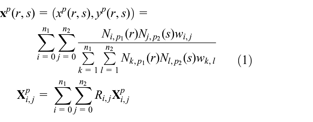
where
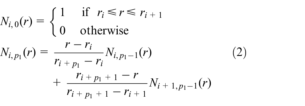
where
In this section, geometry of two types of SSDs, chosen from previous studies (Chan and Albermani, 2008; Ghabraie et al., 2010), is constructed. The first shape, depicted in Figure 1(a), is the original version of SSDs suggested by Chan and Albermani (2008). The results of the experimental test on this damper are used to verify the proposed model in this article. The second shape, depicted in Figure 1(b), was suggested in Ghabraie et al. (2010) where the shape is optimized via topology optimization by using BESO algorithm. This SSD is also used to compare its optimum energy dissipation to the results of the proposed shape in this article under the same conditions.
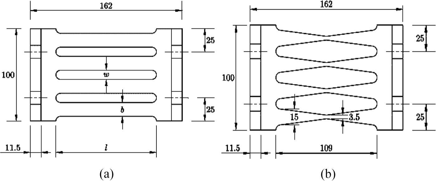
Steel slit dampers: (a) conventional design shape (b = 16.6 mm, w = 8.4 mm, l = 109 mm; Chan and Albermani, 2008) and (b) proposed shape by using BESO in Ghabraie et al. (2010).
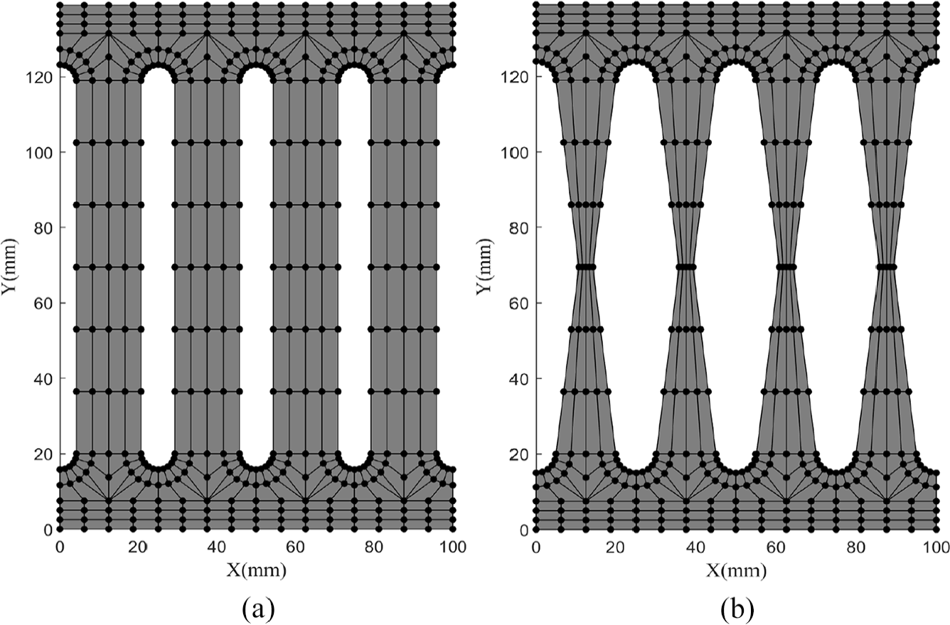
To create both geometries, first, the domains are divided into 22 smaller subdomains or patches. The arrangements of patches are illustrated in Figure 2. Each patch is parametrized by an individual NURBS as defined in equation (1). Therefore, knot vectors in both directions and associated control points, as shown in Table 1, should be defined in each patch. It is noticed that the same number of control points and knot vectors are used for both geometries as shown in Figure 1 and only control points’ positions in the middle patches are located differently so that the shapes are created. The control nets and obtained physical shapes (gray areas) are depicted in Figure 3. It is important to note that the control points do not lay necessarily on the shape especially when the boundaries are curved.
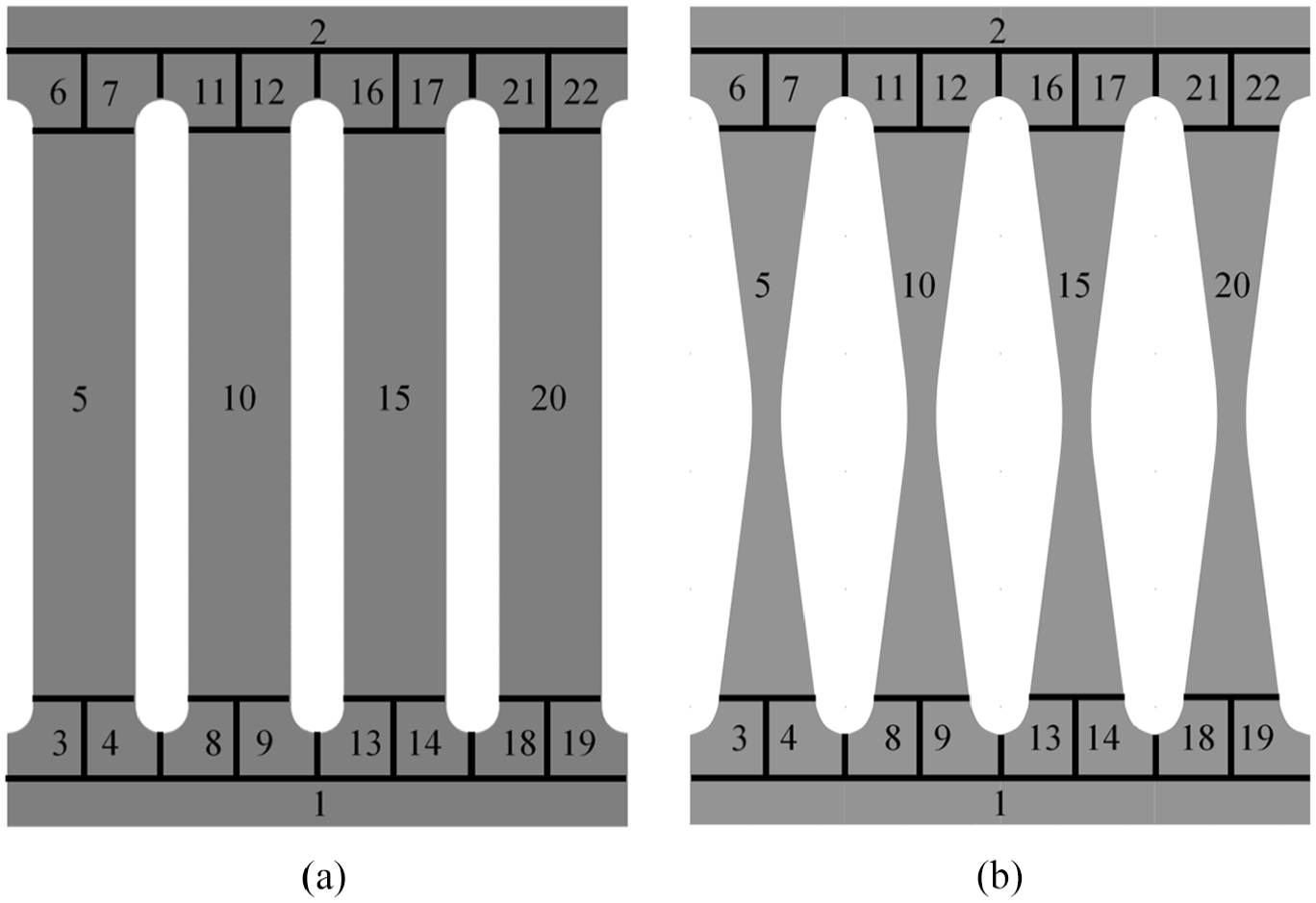
Patches’ arrangements for two dampers in Figure 1: (a) conventional design shape (Chan and Albermani, 2008) and (b) proposed shape by using BESO in Ghabraie et al. (2010).
Number of control points and knot vectors to create the model geometries.

Control net (control points and connected lines) and constructed physical shape (gray area) for the sample dampers in Figure 1: (a) conventional design shape (Chan and Albermani, 2008) and (b) proposed shape by using BESO in Ghabraie et al. (2010).
Numerical formulation of the IGA model
In this article, an isogeometric model is constructed for non-linear analysis and shape optimization of SSDs. Due to relatively their complex boundary shape, especially when the shape is optimized, the IGA method seems a perfect candidate for this purpose. In the previous section, geometry of two well-known SSDs was constructed by B-spline basis functions. In this part, these basis functions are also used to approximate the unknown deformation fields of the problem. Since the dampers are subjected to in-plane lateral loading during earthquake excitations, a plane stress problem can be solved. Therefore, two translational degrees of freedom, that is, displacements u and v, are approximated in B-spline parametric space as
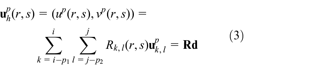
where Rk, l are the non-zero NURBS basis functions which are defined in equation (1) and

where due to material non-linearity, the internal forces vector is non-linear with respect to

For brevity, the internal forces vector is shown by
where
Model verification
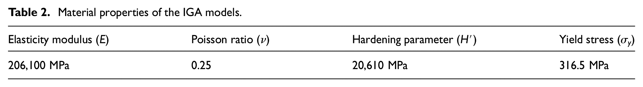
To verify the isogeometric model, outcomes of the conventional SSD experimental test, illustrated in Figure 1(a), are considered. The test setup, cited from Chan and Albermani (2008), is shown in Figure 4. In order to study yielding behavior, linear isotropic strain hardening von Mises material is implemented. The material properties are also shown in Table 2.
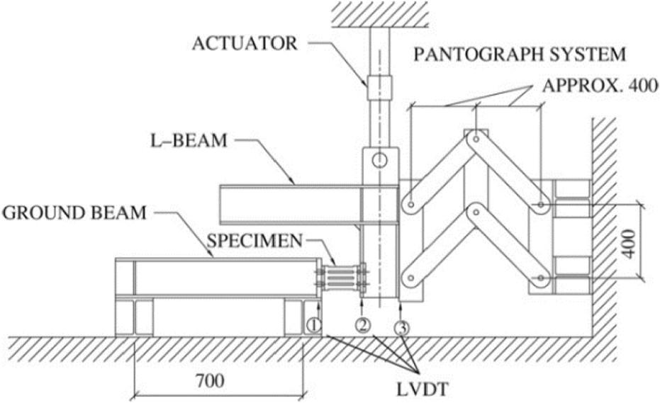
Test setup in Chan and Albermani (2008).
Material properties of the IGA models.
In the experimental test, the SSD is subjected to a 20 mm prescribed displacement in side 2, while side 1 of the damper is fixed, as shown in Figure 4. The problem is also solved with IGA under the same conditions. Figure 5 depicts the load–displacement diagrams for experimental test and FE model from Chan and Albermani (2008), as well as results of the isogeometric numerical model. Comparing the graphs, reasonable accuracy of the proposed model can be demonstrated. Since limited number of degree of freedoms is considered in numerical models, the experimental measurements show slightly more flexibility especially in non-linear part of the response. Also, uncertainty of the considered hardening parameter might be the reason of crossing the curves at the end of the graph.

Load–displacement diagrams for experimental test (Chan and Albermani, 2008), FE model (Chan and Albermani, 2008), and the present IGA model.
Mesh sensitivity
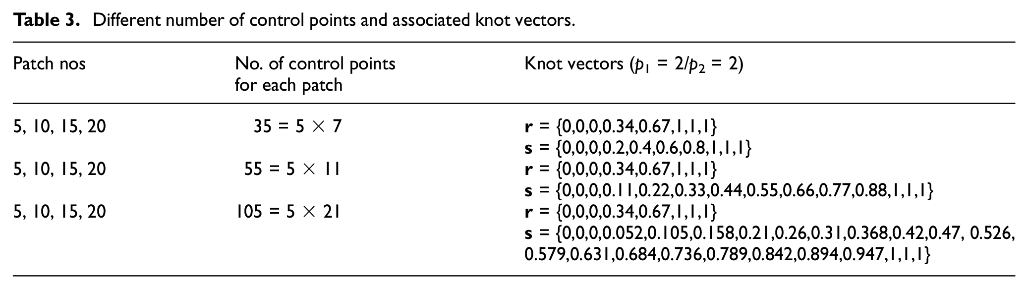
To investigate the effect of number of control points on the results of IGA model, the SSD constructed in Figure 3(b) is considered. For this purpose, the number of control points in middle patches is increased to 55 and 105 as shown in Figure 6. The middle patches are chosen because deformation gradient is higher in comparison with the other parts, and therefore, the results are more sensitive to the number of discretizing points in these regions. The associated knot vectors are depicted in Table 3.
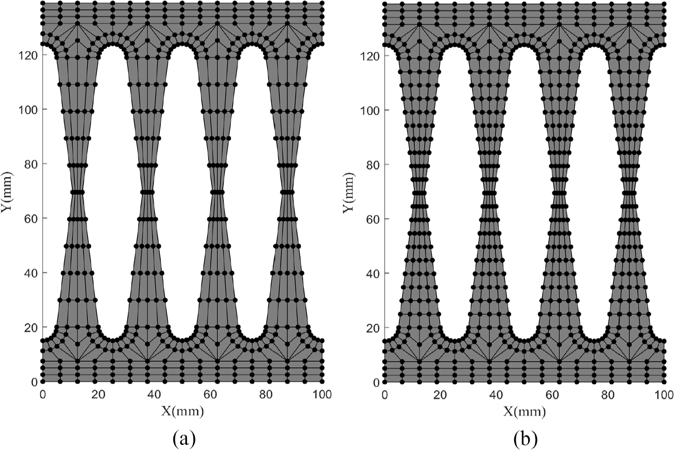
Different number of control points for discretizing middle patches: (a) 55 and (b) 105 control points.
Different number of control points and associated knot vectors.
The prescribed displacement equal to 10 mm is applied to the three models. The load–displacement diagrams of these models are depicted in Figure 7. Comparing obtained results shows that increasing number of control points leads to slightly different behavior in plastic parts of the graphs. Note that the graphs of models with 55 and 105 control points are closer as the model is going to converge. Although considering more degree of freedoms causes more precision in analysis results, less number of control points is regularly considered for shape optimization process. The reason is that having large number of control points causes non-smooth boundaries in optimum shape. However, since the energy dissipation is relatively maximized in the model during the optimization iterations, the slight analysis error does not affect the optimum result. Therefore, in this research, we use the 35-control-point model for optimization process. Notably, an alternative approach is to use different control nets for analysis and geometry models, which is used in the previous literature (Atroshchenko et al., 2018).
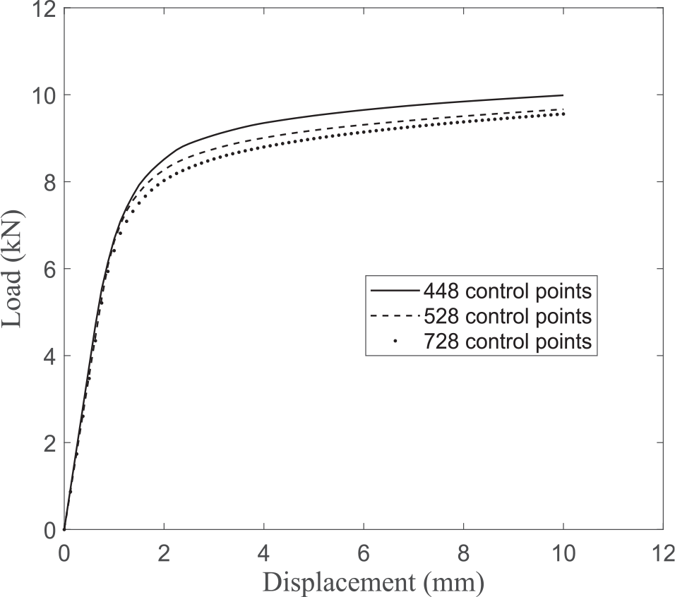
Load–displacement diagrams for different number of control points.
Isogeometrical shape optimization
Definition of optimization problem
Considering a certain amount of material to design a SSD, the dissipated energy depends on boundary shape of the damper. In this article, the goal is to seek an optimum shape of the damper with the aid of isogeometrical shape optimization. To reach this, mathematical form of the optimization problem with the aim of maximizing the dissipated energy U(
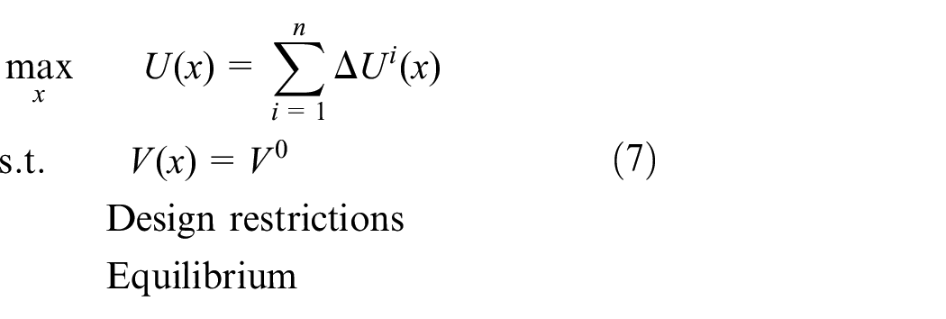
where V(
where
To solve the optimization problem, gradient-based optimization methods or metaheuristic approaches can be used. Since the latter might be slow to converge and time-consuming, the gradient-based method is preferred in this research. To achieve this, derivatives of the objective and constraint functions with respect to design variables should be derived. In the next section, the analytical sensitivity analysis is explained. The flowchart of the optimization process is also depicted in Figure 8.
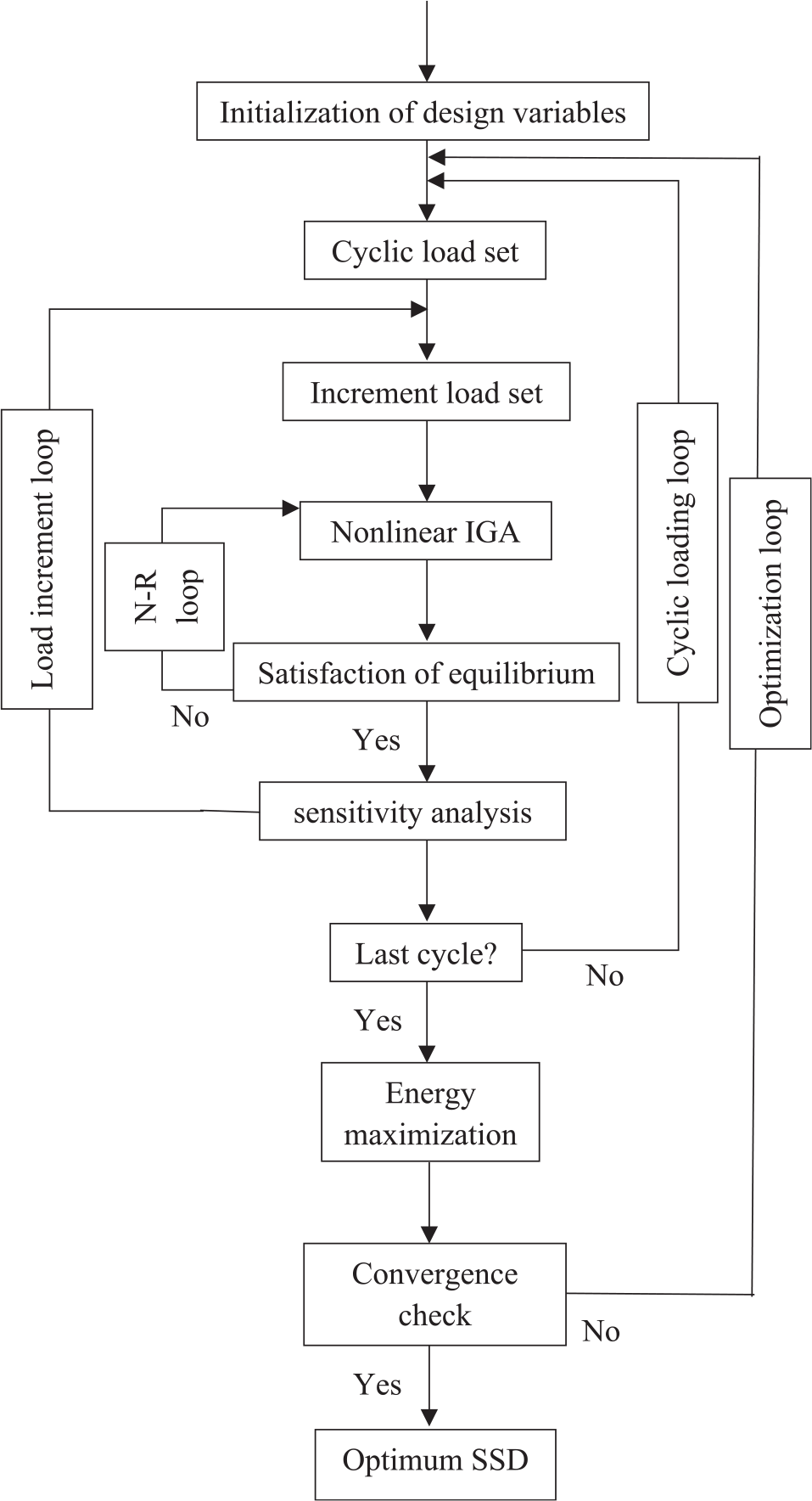
Shape optimization algorithm.
Sensitivity analysis
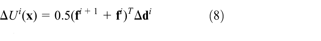
In this section, a direct analytical method is utilized for sensitivity analysis of the optimization problem (Aminzadeh and Tavakkoli, 2019). Based on incremental-iterative procedure for non-linear analysis, the sensitivity of energy integral over a range of prescribed displacement can also be divided into n incremental sensitivities as follows
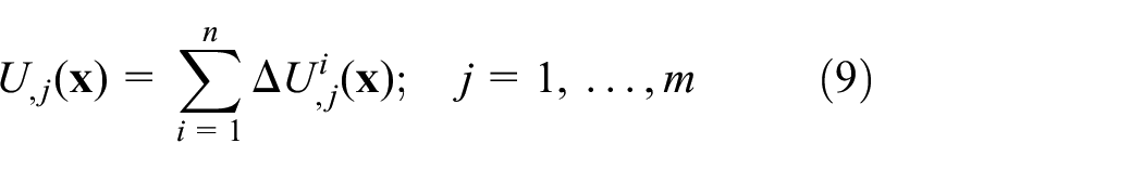
where the subscript, j denotes ∂/∂ xj and xj are design variables of the problem. Also, m is the total number of design variables defined in the optimization problem. Derivative of incremental energy, formulated in equation (8), can be written as follows
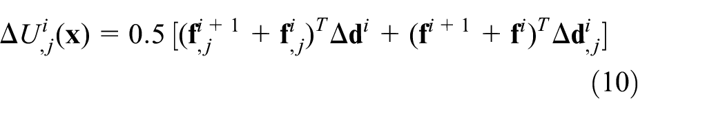
Defining Δ

Since where the forces are unknown such as support reactions, the displacements are known and vice versa, and knowing that known parameters are constant during the optimization process and not dependent on design variables, both incremental force and displacement derivatives can be derived from equation (11) as follows

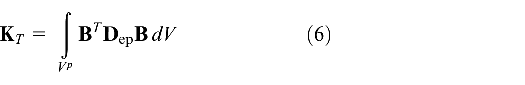
From equation (6), derivatives of tangential coefficient matrix with respect to the design variables can also be calculated as
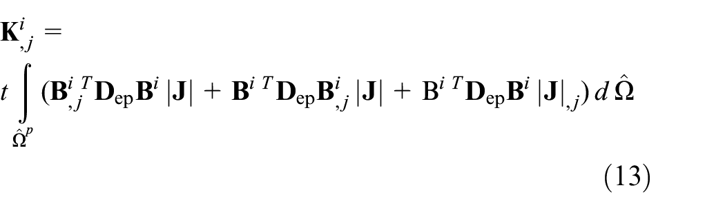
where t is the thickness of the damper. Derivatives of the strain–displacement matrix are required to compute the above equation. To achieve this, differentiating from components of
where from the local support property of NURBS, non-zero basis functions

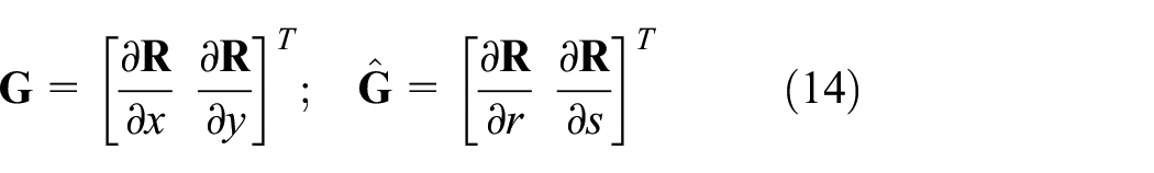
These matrices are also related by the Jacobian matrix

According to geometry definition in equation (1) and description of a new formation of control points’ coordinates

Since

where

To complete equation (13),|
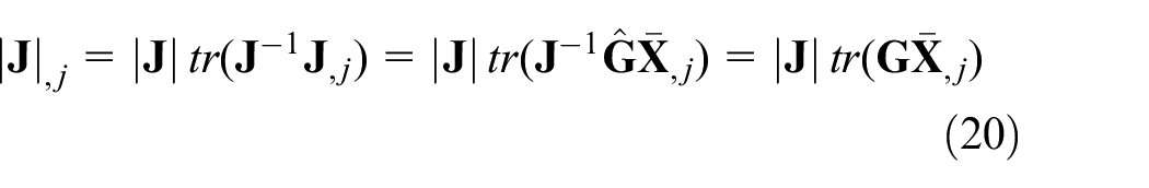
Finally, by computing derivative of tangential coefficient matrix from equation (13) and using the derivatives of incremental vectors of force and deformation with respect to design variables in equation (12), the incremental dissipated energy derivative (equation (10)) is obtained.
Optimum shape of SSD based on the IGA model
In this section, a new SSD is proposed based on isogeometrical shape optimization discussed in previous sections. As mentioned earlier, the optimization problem maximizes the energy dissipation while amount of material is fixed. Therefore, in order to be able to compare the results with previous outcomes in literature, the same volume as considered for optimum shape in Ghabraie et al. (2010) is assumed (Figure 1(b)). Also, for the sake of simplicity, a quarter of the damper is optimized. The design domain and the fixed parts (gray areas) are illustrated in Figure 9(a). Area of material in the design domain is limited to 1797 mm2. It is noted that boundaries of end of slits are curved to avoid stress singularities.
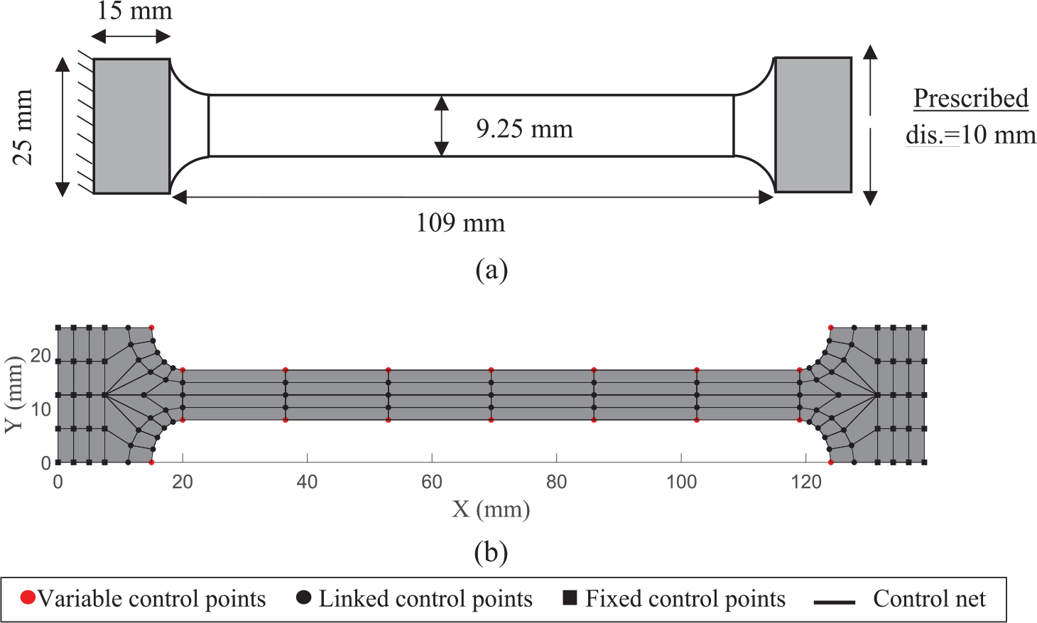
Initial steel slit damper: (a) design domain dimensions and (b) control net of the IGA model.
A quarter of IGA model constructed in section “Numerical modeling of steel slit dampers” is employed here for optimization process. The model includes 7 patches and 117 discretizing control points as depicted in Figure 9(b). The variable and linked control points are shown as red color and solid black circles, respectively. The position of squared points is considered to be constant during the optimization process. Right-hand side of the damper is subjected to an incremental prescribed displacement equal to 10 mm, and 100 number of increments are considered to apply the displacement. The left-hand side is considered as a clamped support.
After calculating the structural response of a load cycle, the von Mises stress contour for initial design is illustrated in Figure 10. It is observed that the right and left regions of the middle patch are yielded while the central zone is still remained elastic. Therefore, it seems the material capacity is not exploited to absorb the energy in the initial design. After optimization, position of control points and the final stress contour of obtained optimum design are shown in Figure 11. In the optimum shape, material was removed from the middle zone to the side regions to increase the dissipated energy so that predefined area remains constant. Convergence history of the objective function in Figure 12 shows maximizing the energy in the optimum shape and converges after 120 optimization iterations.
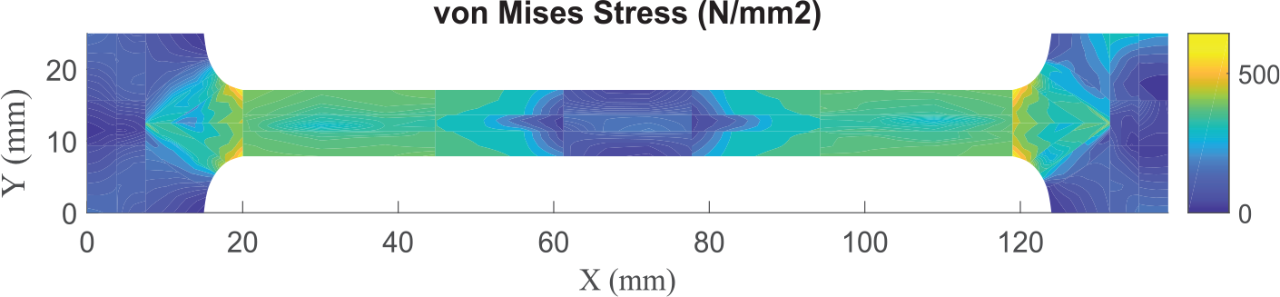
Von Mises stress contour for initial design.
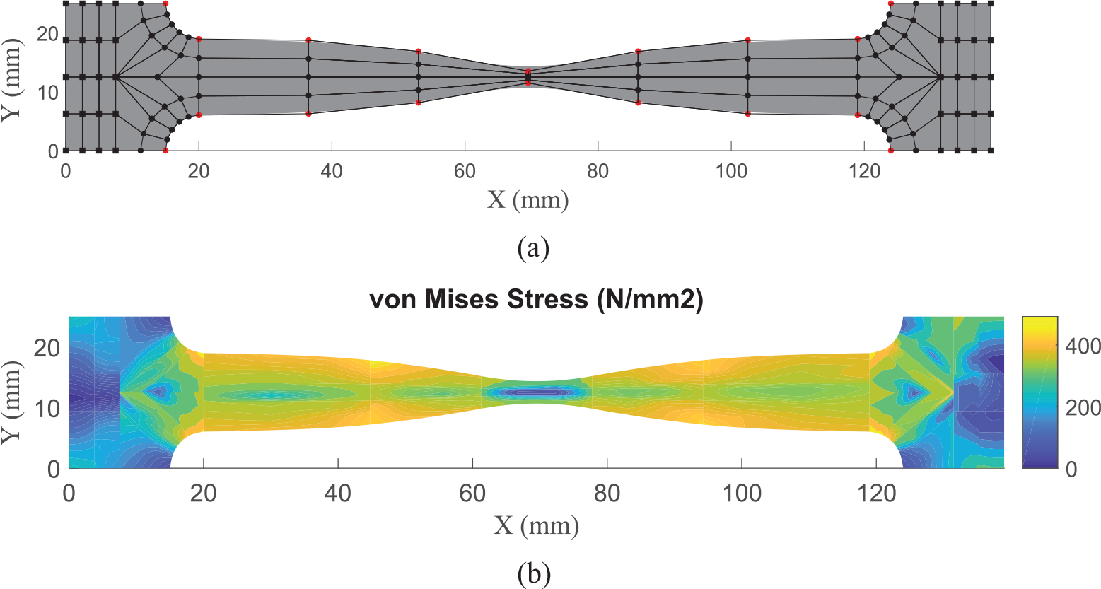
Optimum design of SSD based on IGA model: (a) control net and physical shape and (b) von Mises stress contour.
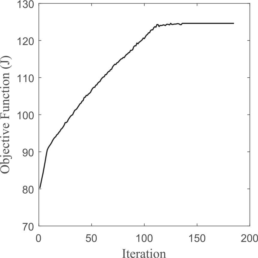
Iteration history of objective function.
For the sake of completeness, a comparative study with proposed shape in Ghabraie et al. (2010) is achieved. For this purpose, the IGA model created in section “Numerical modeling of SSDs,”Figure 3(b), is considered. The control net as well as the von Mises stress contour is shown in Figure 13(e) and 13(f), respectively. The full scale of initial design and the optimum shape are also created and shown in Figures 13(a–d).
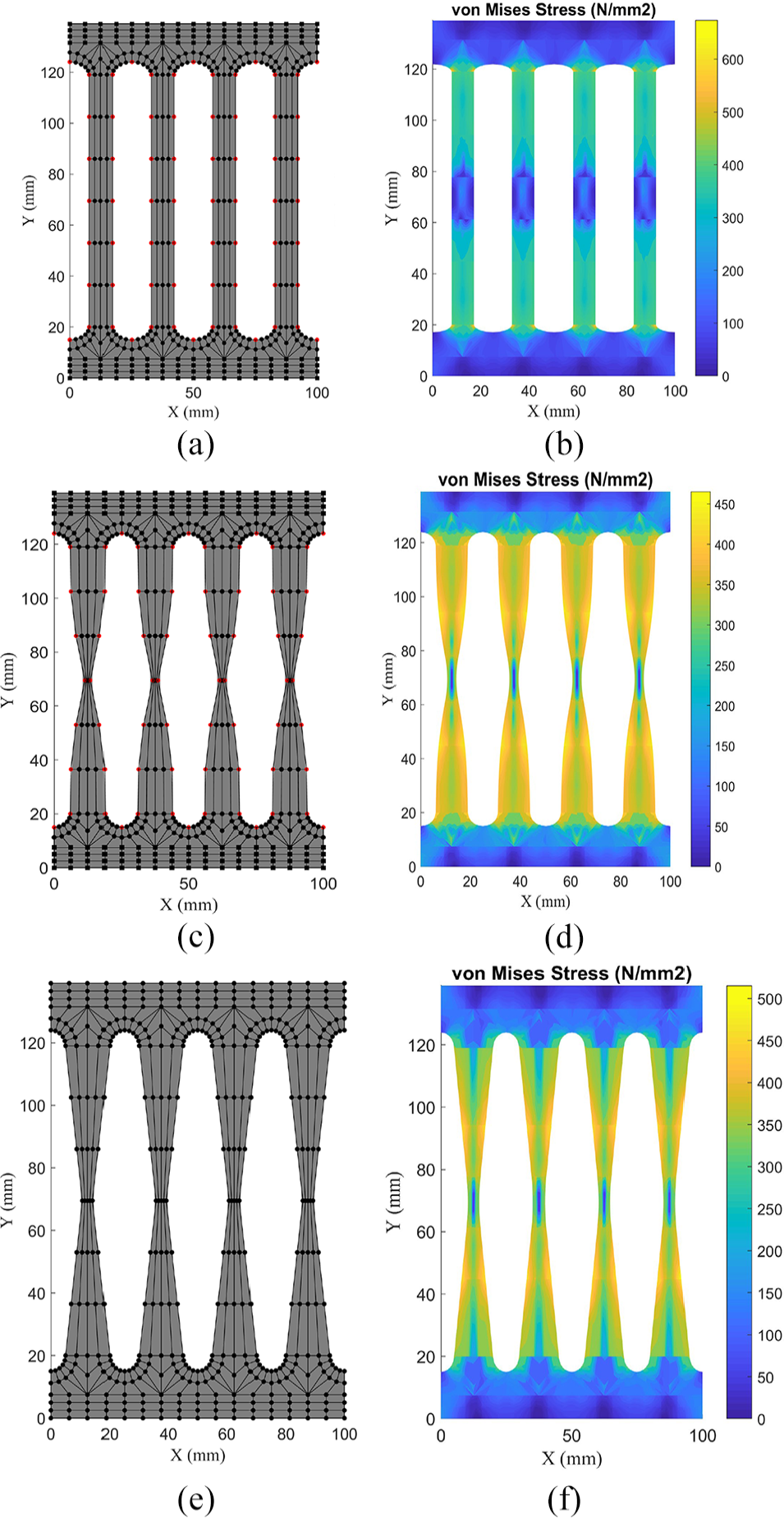
IGA models and von Mises stress contours for (a and b) initial design, (c and d) optimum shape, and (e and f) proposed shape in Ghabraie et al. (2010).
To compare the results, load–displacement curves for initial, optimum shape and the proposed shape in Ghabraie et al. (2010) are shown in Figure 14(a). The cumulative energy dissipation for three SSDs are also depicted in Figure 14(b). At the end of a cycle, the cumulative dissipating energy for initial shape, optimum shape in Ghabraie et al. (2010), and the optimum shape from the proposed method are obtained as 336.7, 452.7, and 509.6 J, respectively. Therefore, the results show 51% and 12% increase in dissipating energy of the proposed damper in comparison with the initial and the optimum shapes in Ghabraie et al. (2010), respectively.
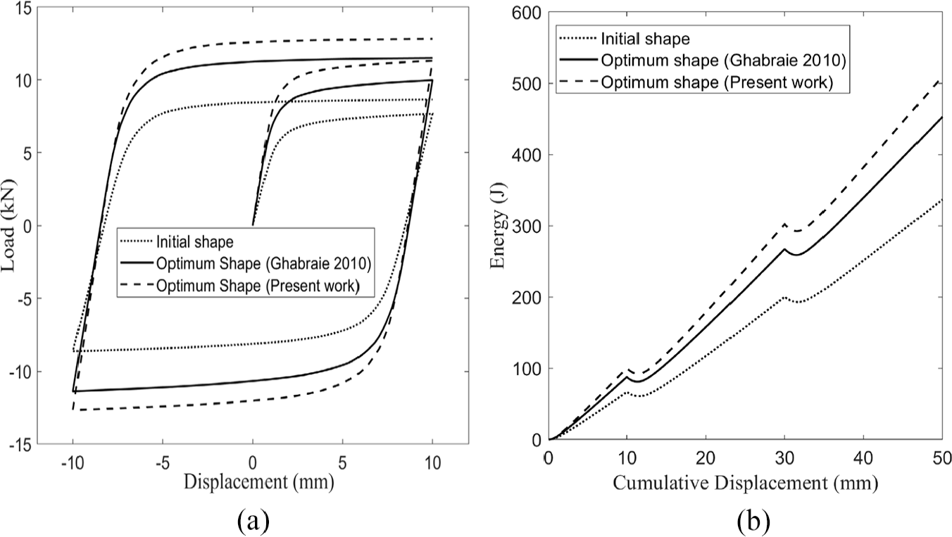
(a) Load–displacement curves and (b) cumulative energy dissipation graphs for initial and proposed shape in Ghabraie et al. (2010) and present optimum shape.
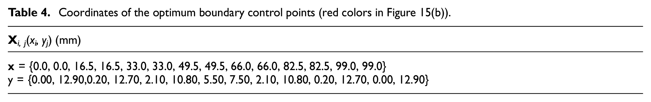
Figure 15(a) shows overall dimensions and physical boundaries of the proposed SSD in this article. Figure 15(b) illustrates the boundaries of one strip of the damper and the coordinates of its boundary control points, depicted by red color, which are indicated in Table 4. Coordinates of the interior control points can also be derived by linear interpolation from the boundary control points. By substituting the coordinates of control points into equation (1), the exact geometry of the damper is obtained.
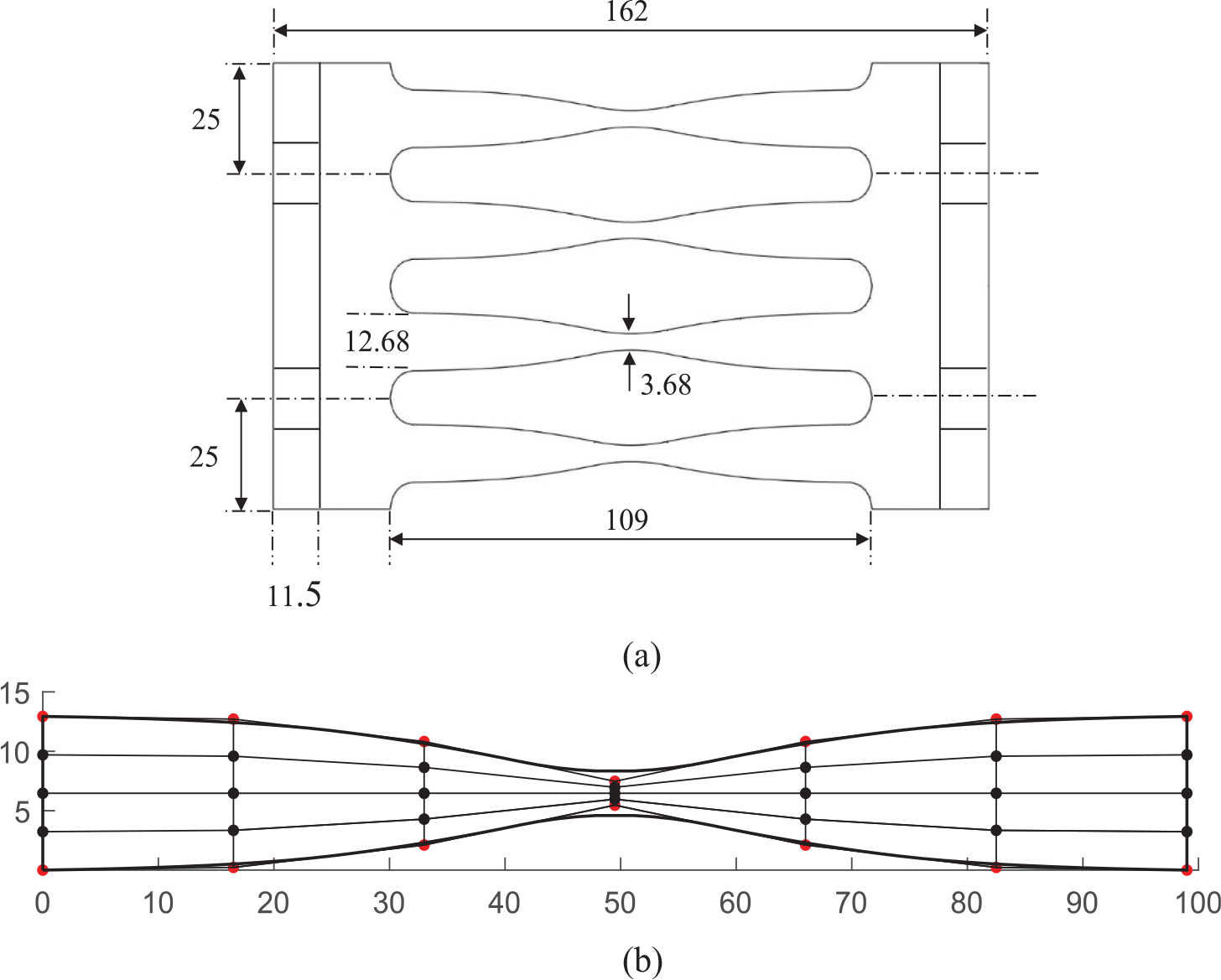
Optimum boundaries of steel slit damper: (a) the entire model and (b) one-strip details with control point coordinates.
Coordinates of the optimum boundary control points (red colors in Figure 15(b)).
Conclusion
In this article, a new shape for SSDs is suggested via isogeometrical shape optimization. The optimization problem is to maximize energy dissipation in a given range of prescribed displacement under a volume constraint. First, the isogeometric model of a conventional SSD is constructed and verified by experimental outcomes in literature. Afterwards, a mathematical-based optimization algorithm is employed to optimize the boundaries of the damper. The obtained optimum shape improves and the energy dissipation is increased by 51% in comparison with the conventional initial shape. The optimum result is also compared with the previous proposed damper in literature and shows 12% enhancement in dissipating energy.
Footnotes
Declaration of Conflicting Interests
The author(s) declared no potential conflicts of interest with respect to the research, authorship, and/or publication of this article.
Funding
The author(s) received no financial support for the research, authorship, and/or publication of this article.