



Abstract
The amount of energy transferred to the ground truly represents the performance of the seismic vibrator. So, it is crucial to investigate the transfer of energy in the vibrator-ground system and how parameters affect it. For this purpose, a model of vibrator-ground system considering frequency change is developed based on half-space theory, and methods of calculating energy transfer is innovatively proposed. Results show that the total energy done by the hydraulic force on the vibrator-ground system in the frequency band of 3–200 Hz is 3.156×10⁵ J, and 9.11% of the energy is transferred to the ground. In addition, effects of structural parameters and soil parameters on energy transfer are carried out. It is concluded that lightweight reaction mass can significantly increase the total energy, but heavier reaction mass generates more ground energy. Baseplate with small mass not only helps the vibrator to transmit energy uniformly but also generates more ground energy above 100 Hz. Larger baseplate area can improve the baseplate-ground interaction to transfer more energy to the ground. For the effects of soil on energy transfer, the ground energy in low-frequency band is mainly dominated by soil elastic modulus, and both elastic modulus and density of soil have great effects on energy transferred to ground at high frequencies.
Keywords
Introduction
Oil and gas exploration considerably depends on technology and equipment. The progress of exploration technology and equipment improves the ability and accuracy of the exploration (Ziolkowski, 2010). With the advantages of high efficiency, environmental protection, and safety, seismic vibrator as shown in Figure 1(a) has become the most popular sources in land exploration (Pecholcs et al., 2012; Sallas, 2010; Wei et al., 2010). As oil and gas exploration toward deep, ultra-deep and unconventional resources, the seismic vibrators are required to improve their exploration ability and transfer more energy into the earth. To meet these requirements, researchers and industry have conducted two aspects of attempts. One is to increase the rated output (peak-force) of the vibrator, and the other is to analyze and optimize the vibrator structure.
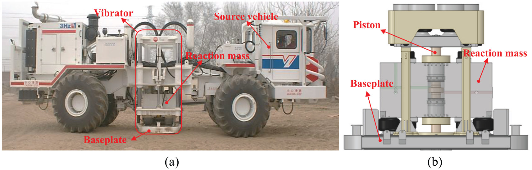
(a) Seismic vibrator and (b) the structure of vibrator.
In the past few decades, the peak-force of seismic vibrator has steadily increased from 200 to 340 kN, and 280 kN peak-force vibrators are commonly used (Wei et al., 2012). Larger seismic vibrator produces more output but increases the complexity of the system, which is not conducive to maintenance (Cao et al., 2016). Besides, the off-road performance of the source vehicle will be significantly reduced, thus limiting its exploration terrain (Chen et al., 2019). So the peak force of the seismic vibrator dose not continue to increase but stabilizes at 280kN. Due to the disadvantages of increasing peak-force, lots of researches focus on studying vibrator structure and vibrator-ground dynamics.
Vibrator as shown in Figure 1(b) is the core component of seismic vibrator, which consists of a reaction mass, a baseplate, a piston, and other auxiliary structures. Analyzing the vibrator structure is to evaluate each element in the vibrator system and ensure each part successfully contributing to generate desirable output signal. To extend the excitation bandwidth of the vibrator, some significant works are accomplished. It is concluded that reaction mass stroke was the main factor limiting the bandwidth toward low frequency, and the servo valve system was the main factor limiting the bandwidth toward high frequency (Wei, 2008, 2009a). Solutions are also proposed, such as Li et al. (2019b) carried out method and application to extend low frequencies, and Bagaini (2008) and Dean (2014) developed methods of sweep to improve the vibroseis data.
Harmonic distortion is also one factor decreasing the quality of the output signal (Lebedev and Beresnev, 2004, 2005). Reust (1991) introduced a pressure-control servo valve to improve the signal-to-noise ratio of the output, Wei and Phillips (2012, 2013a) reduced the low-frequency harmonic distortion through improved vibrator control algorithms, and Jiang et al. (2018) deduced the vibration noise through optimizing the hydraulic oil passageway.
Among these issues, ground force is the main research content. In 1984, Sallas (1984) introduced using ground force to describe the output of vibrator. The ground force is the force that the baseplate applies on the ground, which is the weighted sum of the reaction mass and the baseplate accelerations multiplied by their respective mass. This method is simple and practical and widely used in the industry (Wei et al., 2010; Ziolkowski, 2010). Many researchers have demonstrated the complexity between the vibrator and ground (Dean et al., 2015; Ley et al., 2006; Martin and Jack, 1990) and suggested that the weighted sum method is not a good estimation of the ground force (Boucard and Ollivrin, 2010; Rowse and Tinkle, 2016; Saragiotis et al., 2010; Wei, 2009b). So, some approaches are developed to describe the interaction of vibrator-ground system and improve the ground force, providing many innovative perspectives. A simple model established by Tinkle and Rowse (2010) indicated that acceleration signals of reaction mass and baseplate can reflect the resonance frequencies and damping factors. The responses of the vibrator are different between low frequencies and high frequencies (Huang et al., 2017; Wei and Phillips, 2013b), and the reaction mass dominates the low-frequency response, and the baseplate plays a crucial role at high frequencies (Li et al., 2019a). Methods to increase the ground force including strengthening the contact between the baseplate and the ground with a rubber pad (Wei, 2010), designing a baseplate with new structure and material (Reust et al., 2015), properly increasing the weight of the reaction mass (Baeten et al., 2010; Rademacker et al., 2005), and extending the fatigue life of the baseplate (Chen et al., 2017). These methods have improved the exploration capability of the vibrator to some extent.
The essence of seismic vibrator exploration is converting the internal energy of the hydraulic oil to the mechanical energy of the vibrator and then transferring it to the ground. Many previous studies are about reducing the distortion of converting internal energy to mechanical energy and improving the mechanical energy of the vibrator. Few studies have focused on the energy transferred to ground. In this article, a model of vibrator-ground system considering frequency change to study the energy transfer is established, and a field experiment is conducted to validate this model. In addition, the effects of parameter on energy transfer at different frequencies are investigated. This research will be helpful for optimizing vibrator and improving seismic vibrator exploration.
Establishment and validation of the model of vibrator-ground system
Establishment of the model of vibrator-ground system
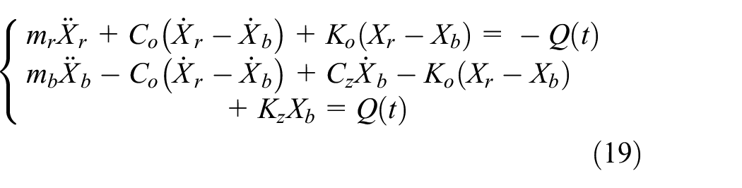
The responses of the vibrator at different frequencies are various, and traditional models cannot reflect this phenomenon. The key to establish a vibrator-ground model is describing the interaction between the baseplate and the ground in consideration of frequency. In civil engineering, the half-space theory is widely used to solve the foundation-ground vibration problems at different frequencies (Hamidzadeh-Eraghi and Grootenhuis, 2010; Kausel, 2010; Lou et al., 2011). The baseplate vibrating on the ground is similar to the foundation vibrating on the ground, which provides a reference for the establishment of a vibrator-ground model. According to half-space theory, a model of vibrator-ground system is proposed as Figure 2(a) shows. In Figure 2(a), mr is the mass of reaction mass, mb is the mass of baseplate, Xr is reaction mass’ displacement, Xb is the baseplate’s displacement, Ko is the hydraulic spring, Co is the hydraulic damping, Kz is the equivalent dynamic stiffness of vibrator-ground system, Cz is the equivalent dynamic damping of vibrator-ground system, and Q(t) is the hydraulic force. To solve the vibrator-ground system, the model of baseplate-ground system as shown in Figure 2(b) should be investigated first.
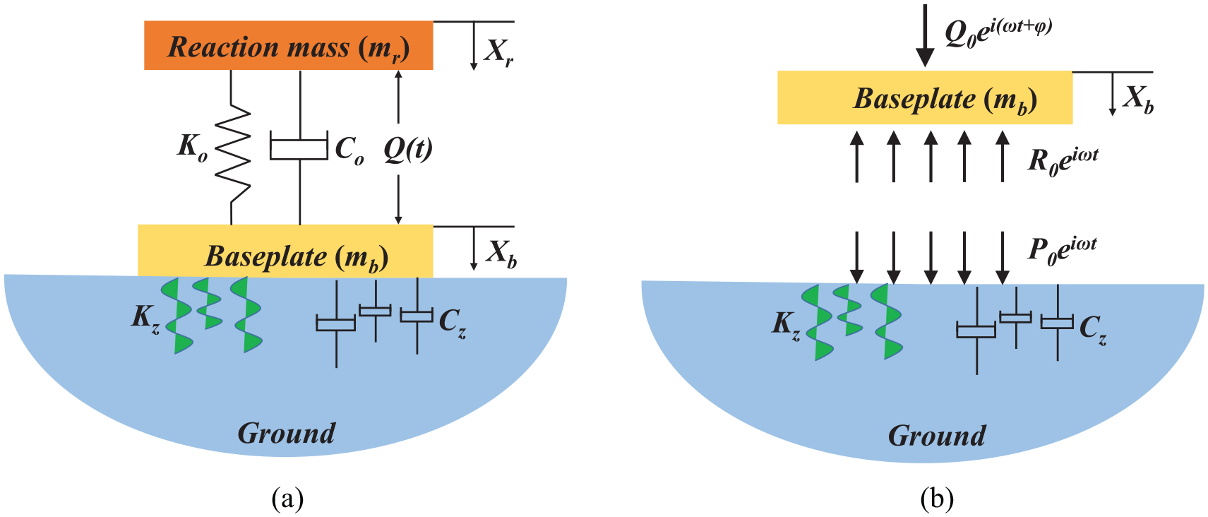
(a) Vibrator-ground system and (b) mechanical relationship between the baseplate and the ground.
For an axisymmetric structure, the wave equations are given as follow
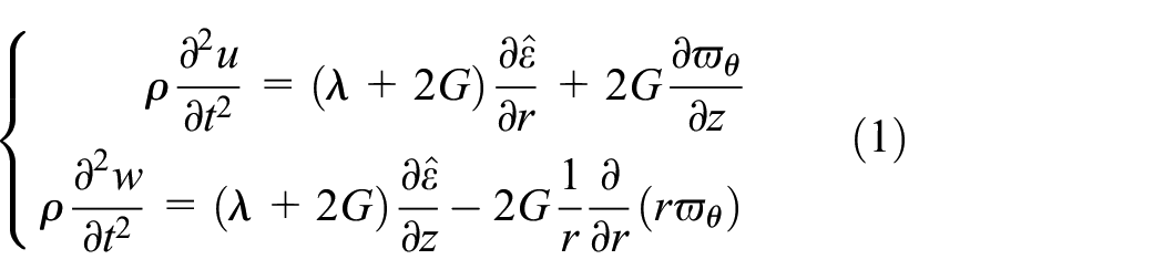
where ρ is soil density, G is soil shear modulus, μ is Poisson’s ratio, t is time,
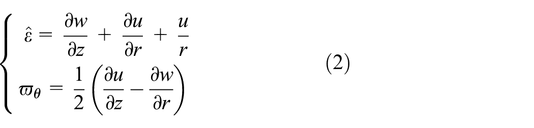
The volumetric strain
On the ground surface (z = 0), if the dynamic force acting on the ground is P0e iωt , the vertical stress and shear stress can be, respectively, given as

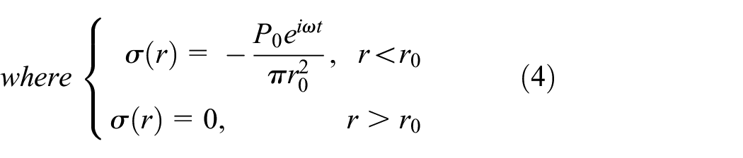
and r0 is baseplate’s equivalent radius and
The baseplate’s vertical displacement w(r, 0) in Hankel transformation is

where J0(pr0) is the zero-order Bessel function,

where J1(pr0) is the first-order Bessel function.
With Hankel inversion to equation (5), it can be got as follow

Substituting equations (5) and (6) into equation (7) yields

Assuming the surface displacement is approximately equal to the displacement of center point (r = 0), and baseplate and the ground are well coupled, the vertical displacement can be written as follow (Sung, 1954)

where f1 is the function of dimensionless frequency a0, so is f2. a0 is equal to


For equation (9), the dynamic force can be given as

Figure 2(b) shows the mechanical relationship between the baseplate and the ground. Q0ei(ωt + φ) represents external force, P0eiωt represents the force baseplate applying on the ground, and R0eiωt is the reactive force. R0eiωt can be written as
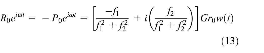
So the kinetic equation of the baseplate is

Substituting equation (13) into equation (14) yields
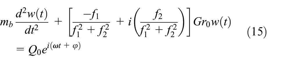
For periodic force,
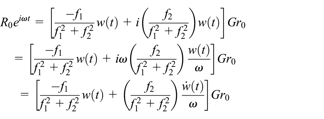
Then, equation (15) is in following form
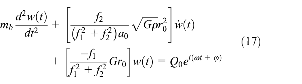
The equivalent dynamic stiffness Kz and equivalent dynamic damping Cz can be obtained as follows

The equivalent dynamic stiffness and the equivalent dynamic damping are both functions of frequency, which can describe the response of the vibrator system under frequency change. This is a significant improvement over traditional models. The kinetic equations of the vibrator-ground system in Figure 2(a) are drawn as
Validation of the model of vibrator-ground system
As ground force is the common indicator of vibrator output in field operation, it is employed to validate the model. The ground force of the vibrator-ground system in Figure 2(a) is given as

The hydraulic force applying on the piston face is also called sweep signal, as its amplitude and frequency are both functions of time. The amplitude changes sinusoidally, and the frequency increases linearly. The function of sweep signal is written as follow
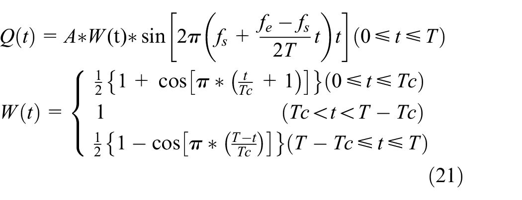
where A is the amplitude of hydraulic force, T is the sweep length, t is the time, Tc is the taper time, and W(t) is the cosine taper to ensure smooth processes at starting and ending vibration.
A field test was carried out to validate the model of vibrator-ground system through the comparison of ground forces obtained from the test and calculated by the model. In the field test, the sweep frequency was from 5 to 105 Hz, the sweep length was 10 s, the amplitude of hydraulic force was 250,000 N, and 0.5-s cosine taper was applied at start and end of sweep. The feedback control was closed in the test. The test was conducted by an AHV-IV seismic vibrator on stiff clays, and the ground force was detected by load cells. The load cell is a strain sensor whose surface is a circle with a diameter of 20 cm, which can directly measure the true ground force, and eight load cells were used in the test. The sweep signal is as shown in Figure 3. Figure 3(a) shows the full sweep, and Figure 3(b) demonstrates the 0.5-s cosine taper at the end of sweep. The specifications for the model and the test are as shown in Table 1.
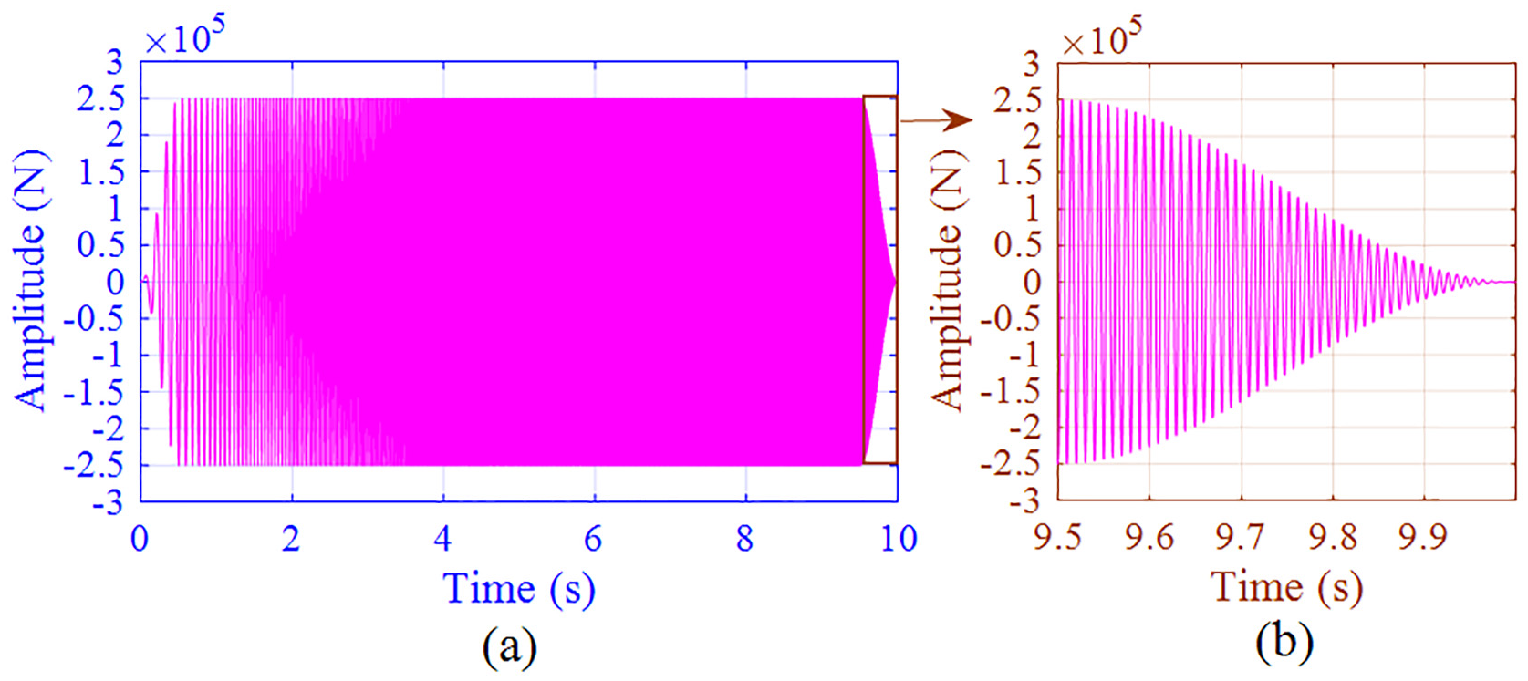
Sweep signal: (a) full sweep, and (b) cosine taper.
Specifications for the vibrator-ground system model and the test.

Figure 4 demonstrates the comparison of ground forces between the field test and the model. The red curve and the purple curve are the ground force calculated by equation (20) and the ground force obtained from the test, respectively. Some details are provided as shown in the brown box and the green box. It is can be seen that the model’s ground force changes with the increase of sweep frequency. At low frequencies (or before 1.5 s of the sweep), due to insufficient oil supply and instability of the hydraulic system, the reaction mass does not move in accordance with the sweep signal, resulting in distortion of the ground force as the purple curve shows in the brown box. The vibrator-ground model does not cover the hydraulic system, so it cannot reflect this distortion. However, the amplitude and phase of the model are basically consistent with the experiment data during the full sweep, except frequencies at where the ground force suffering distortion. This comparison shows that the results calculated by the model agree well with those of the field test in the full sweep, indicating that this model is suitable for analyzing the vibrator-ground system.
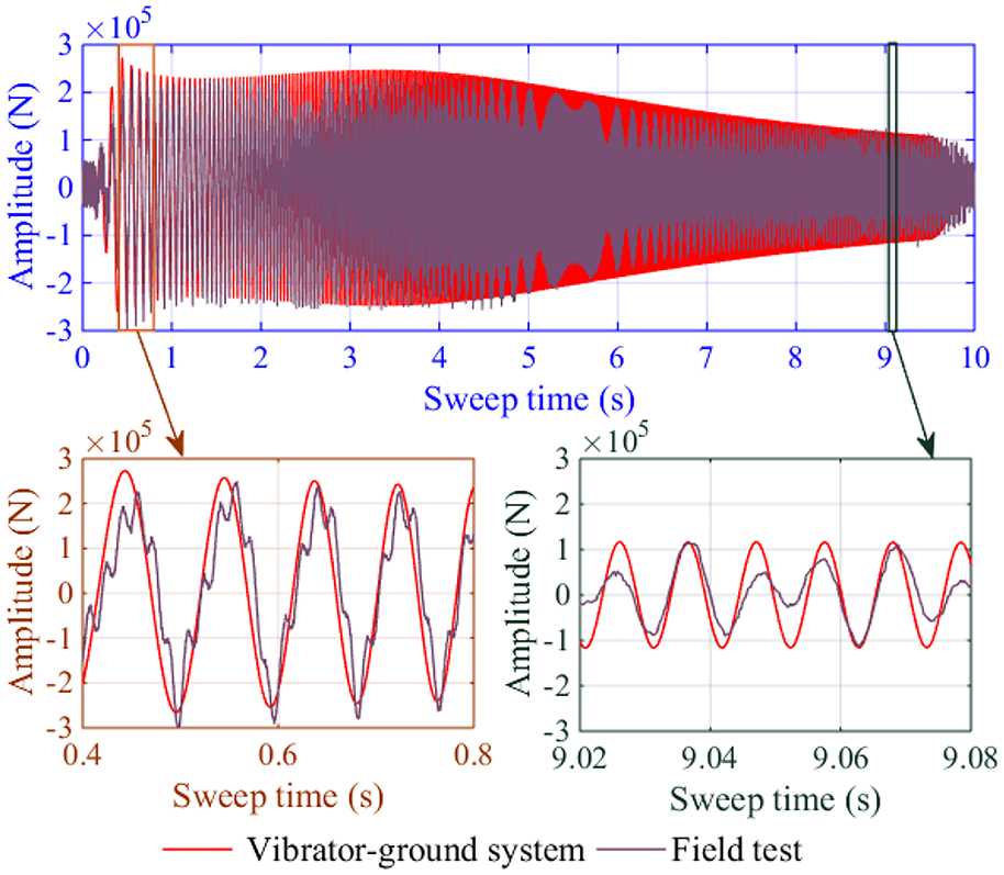
Comparison of ground forces between the field test and the model.
Methods for calculating energy transfer and energy transfer rate of the vibrator-ground system
Calculation of energy transfer
The ground force reflects the performance of the vibrator itself. However, the ground force cannot indicate the energy captured by the ground. The absorbed energy by ground determines the depth of seismic wave transmission and the strength of reflected signal, which directly represents the actual exploration capability of the vibrator. Here, we define that energy transfer is the energy transferring in the vibrator-ground system. Ground energy refers to the energy transferred to the ground, that is, how much useful work the vibrator performs to the ground. Due to the limitation of field technology and equipment, it is difficult to calculate energy transfer. However, based on the established vibrator-ground system model, method of calculating energy transfer can be developed.
Assuming that the action time of the baseplate on the ground is divided into n time intervals and each time interval is Δt, then the total energy of the system at the ith (0 < i ≤ n) time is Es(i). And Es(i) = Es(i-1) + ΔE, wherein ΔE represents the energy increased from time (i – 1)th to time ith. The total work Es by hydraulic force Q(t) is divided into two parts. One is Er, representing the total work done on the reaction mass (mr) and the corresponding spring (Ko) and damping (Co). The other is Eb, indicating the total work done on the baseplate (mb) and the corresponding spring (Kz) and damping (Cz). And through integral calculation, Er and Eb are calculated and added together to obtain the total work done by the hydraulic force on the system. The total work done by the vibrator on the ground can be regarded as the total work done by the baseplate compressing the spring, and this work is ground energy Eg. So, Eg is part of Eb. From the above definition and calculation, the relationship between each energy and frequency (time) is obtained, as shown in Figure 5.
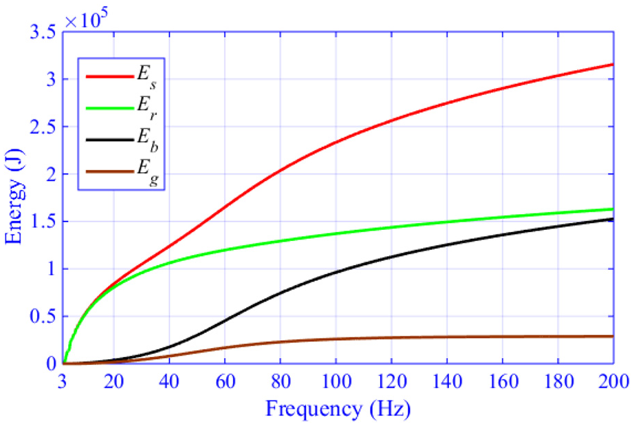
Energy transfer of vibrator-ground system at different frequencies.
For full observation of the effects, the ending frequency of sweep signal is extended to 200 Hz. From Figure 5, it can be seen that the work performed by the hydraulic force on the system is divided into two phases, below 20 Hz and above 20 Hz. In the frequency band below 20 Hz, the total energy increases rapidly, and above 20 Hz, its growth rate is relatively slow. The total work done in the full sweep is 3.156 × 10⁵ J. At the beginning of the sweep (the frequency is below 20 Hz), both Es and Er increase sharply, and they are almost equal, indicating that the hydraulic force mainly works on the reaction mass. As the frequency increases above 20 Hz, Er increases slowly, while Eb grows quickly. It is consistent with the structural response of previous study that the reaction mass dominates the system in the low-frequency band, and the baseplate gradually occupies the dominant position at high frequencies (Li et al., 2019a).
The energy transfer shows that the work of the vibrator on the ground is very limited below 20 Hz. When the frequency is higher than 20 Hz and less than 80 Hz, the energy received by the earth increases significantly; when the frequency is further increased to above 80 Hz, the vibrator does less and less work on the ground. This also explains that the ending frequency of hydraulic force in field operation is usually below 100 Hz, instead of continuing to expand to higher frequencies. Individually expanding the sweep frequency cannot effectively improve the exploration effect because the energy transmitted into the ground is very limited at high frequencies. In this case, the reflected signal from the underground structure is weak and the signal-to-noise ratio is also low.
Calculation of energy transfer rate
At a certain time (frequency), the energy transfer rate is the ratio of the transferred energy to the total energy. So, the energy transfer rate of reaction mass

Similarly, the energy transfer rate of baseplate


Figure 6 shows energy transfer rate of the vibrator-ground system at different frequencies expressed as % of total energy. From 3 to 20 Hz, more than 95% of the energy is transferred to the reaction mass and its auxiliary structures (spring and damping). With the increase of frequency, the energy transfer rate in 20–80 Hz decreases sharply, and 63.47% of the energy is transmitted at 80 Hz. At frequencies above 80 Hz, the energy transmitted by the system through the reaction mass is slowly decreasing. Finally, 51.63% of the energy is transmitted to the reaction mass and its auxiliary structures during the entire sweep. According to Miller and Pursey’s (1955) research, the energy radiated into the ground generates compressional, shear and surface waves, and the percentages of power in the three waves are 6.9%, 25.8%, and 67.4%, respectively.
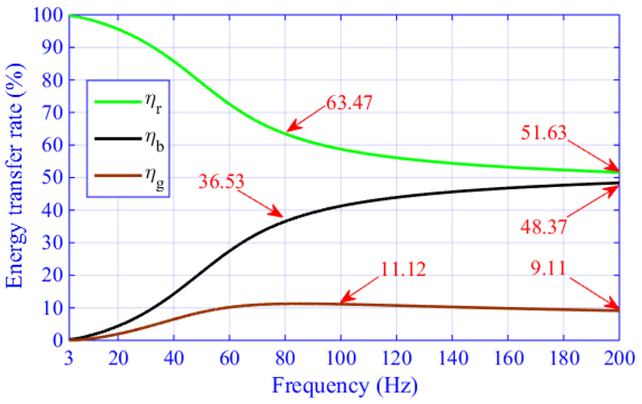
Energy transfer rate of the vibrator-ground system at different frequencies expressed as % of total energy.
In the 3–80 Hz bandwidth, the system’s work on the baseplate and its auxiliary structures steadily increases, and 36.53% of the energy in this frequency band is transferred. As the frequency further increases, the rate grows slowly, and finally 48.37% energy is passed through the baseplate.
The work done by the vibrator on the ground increases rapidly at 20–80 Hz. With the further increase of the frequency, the energy transferred to the ground decreases slightly, and finally 9.11% of the energy is passed to the ground. And at 100 Hz, 11.12% energy is transferred to the ground, which is very close to simulation result (12.9%) (Huang et al., 2016). In field operations, increasing the sweep time will increase the energy transmitted to the ground by the system, but for the energy transfer efficiency, there is almost no growth. On the whole, most energy of the system is consumed by the reaction mass and the baseplate, and the proportion of energy performed by the system on the ground is very small. The efficiency of the energy transfer is very low as most of the energy is wasted. Therefore, instead of increasing the peak-force level of seismic vibrator, improving the energy transfer rate of ground is an effective way to improve its exploration capability.
Effects of parameters on energy transferred to ground
Effects of mass of reaction mass
As energy transferred to ground truly represents the exploration ability of seismic vibrator, it is necessary to investigation the effects of parameter on energy transfer. From the model of vibrator-ground system, it is known that the valuable parameters involved in this analysis include mass of reaction mass of baseplate, baseplate area, soil elasticity modulus, and soil density. In the analysis, the parameter values in Table 1 act as bases, and 0.5 times, 0.75 times, 1.25 times, and 1.5 times of the bases are used as comparisons.
Figure 7 shows the effects of mass of reaction mass on energy transfer at different frequencies, and plot (a), plot (b), and plot (c) are total energy, energy transferred to ground, and energy transfer rate, respectively. And local details are shown in brown box. As shown in Figure (7), a small weight of the reaction mass can significantly increase the total energy of the system, but the energy transferred to ground is reduced, resulting in a significant reduction in the energy transfer rate. Heavier reaction mass generates more energy to ground, but this effect is very limited. As the reaction mass is not directly connected to the ground, the effect of the reaction mass on the energy transferred to ground is depended on the influence of the reaction mass on the baseplate.
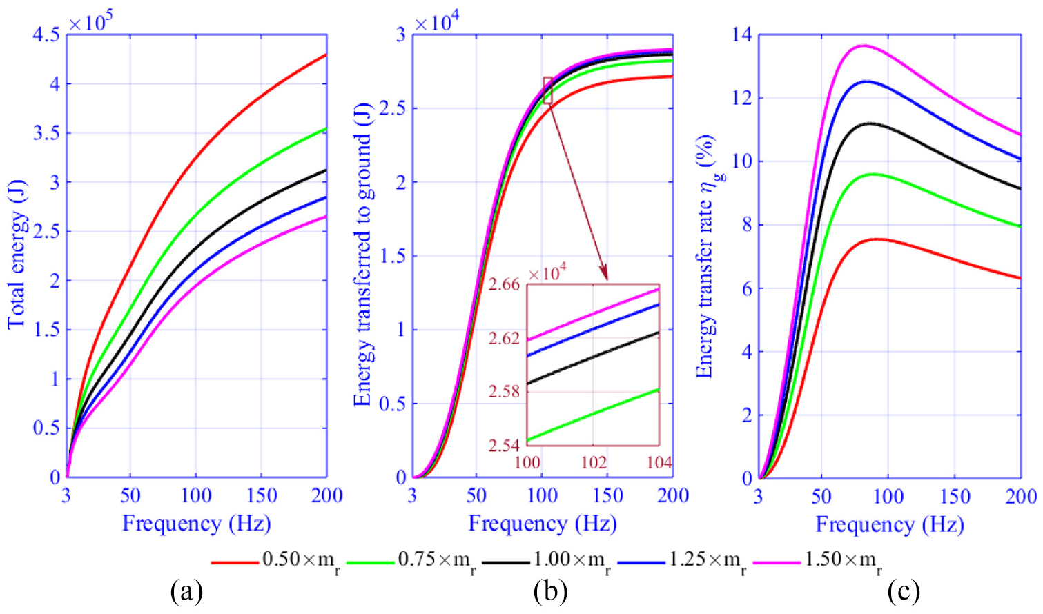
Effects of mass of reaction mass on energy transfer at different frequencies: (a) total energy, (b) energy transferred to ground, and (c) energy transfer rate.
Smaller effect of reaction mass on baseplate leads to weaker impact of reaction mass to ground. Increasing the mass of the reaction mass in an equal proportions does not produce an equal proportion of effect on baseplate or an equal proportion of energy passed to ground, as shown Figure 7(b). Because the interaction between the reaction mass and the baseplate is constant, it is difficult for a heavier reaction mass to have a greater impact on the baseplate, leading to a limited effect on the ground.
Effects of baseplate mass
Figure 8 illustrates the effects of baseplate mass on energy transfer at different frequencies, and details are also shown in the brown boxes. It can be observed that the influence of baseplate mass on energy transfer at the different frequency has phased characteristics. As shown in Figure 8(a), when the frequency is in the range of 3–90 Hz, the baseplate has almost no effect on the total energy, and above 90 Hz lighter baseplate generates more total energy. In Figure 8(b), heavier baseplate can transfer more energy to the ground below 100 Hz. However, the ground energy transferred by the lightweight baseplate is more uniform, as it can be clearly seen that below 125 Hz the curve of 0.5 times baseplate mass is almost a straight line, indicating that lighter baseplate can transfer more energy to the ground in high-frequency band. As the frequency increases, the energy transfer rate increases first and then decreases, and lightweight baseplate has lower energy transfer rate, as shown in Figure 8(c).
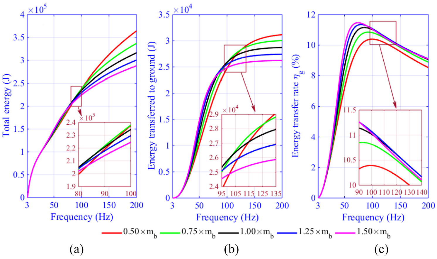
Effects of mass of baseplate on energy transfer at different frequencies: (a) total energy, (b) energy transferred to ground, and (c) energy transfer rate.
Heavy baseplate converts a large amount of energy into its own kinetic energy, resulting in useless work. At the end frequency of 200 Hz, the lighter baseplate transfers more energy than the heavier baseplate. Baseplate with small mass not only helps the vibrator to transmit energy uniformly but also generates more ground energy in the high-frequency band. If the end frequency is further increased, the baseplate with 0.5 times the weight will eventually transfer more energy, and this is why the designer reduced the mass of the baseplate (Wei et al., 2012).
Effects of baseplate area
Figure 9 shows effects of baseplate area on energy transfer at different frequencies. Figure 9(a) demonstrates that the baseplate area has almost no effect on the total energy below 50 Hz, and larger baseplate area produces more total energy above 50 Hz. For the energy transferred to ground, a larger baseplate area generates more transferred energy, which is very obvious in the high-frequency band, as shown in Figure 9(b). A larger baseplate area also leads to a higher transfer rate as Figure 9(c) demonstrates.
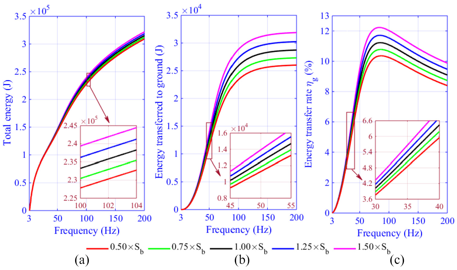
Effects of baseplate area on energy transfer at different frequencies: (a) total energy, (b) energy transferred to ground, and (c) energy transfer rate.
Since the energy in the high-frequency band is mainly converted into the kinetic energy of the baseplate, the increase in ground energy beyond 100 Hz is small. The effects of different baseplate areas on the energy transfer come from the changes in equivalent dynamic stiffness. Large baseplate area can improve the interaction between the baseplate and the ground, and increase the energy transmitted to the ground. However, due to the limitations of vehicle structure and baseplate mass, the baseplate’s area cannot be increased arbitrarily.
Effects of soil elasticity modulus
Figure 10 shows effects of soil elasticity modulus on energy transfer at different frequencies. As shown in Figure 10(a), when the frequency is less than 25 Hz, the elastic modulus has little effect on the total energy; when the frequency is further increased, lower soil elastic modulus brings more total energy. In Figure 10(b), lower elastic modulus is more conducive to transfer energy below 80 Hz, and above 150 Hz, higher elastic modulus generates more ground energy. As shown in Figure 10(c), the energy transfer rate grows and then decreases, generating an inflection point of frequency. The inflection frequency of smaller elastic modulus is lower, as the brown box shows. At the end of sweep, a larger elastic modulus results in a higher energy transfer rate.
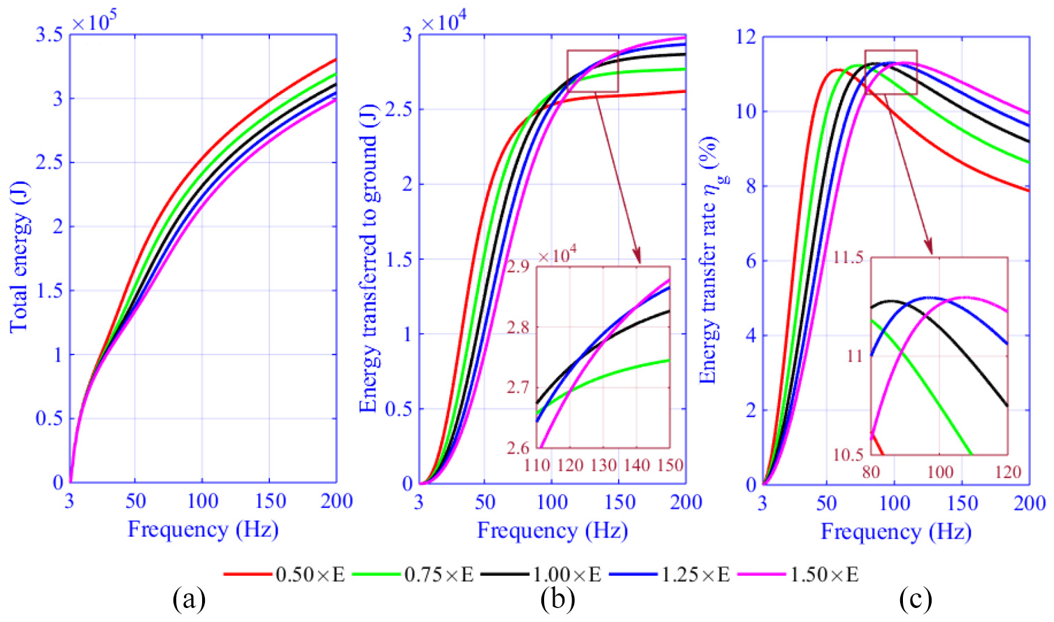
Effects of soil elasticity modulus on energy transfer at different frequencies: (a) total energy, (b) energy transferred to ground, and (c) energy transfer rate.
The effects of the soil elastic modulus on energy transfer represent the influences of soil with different levels of hardness on energy transfer. High elastic modulus means hard soil, and low elastic modulus represents soft soil. At high frequencies, the displacement of the baseplate is smaller (Li et al., 2019a), but higher elastic modulus (indicating larger equivalent dynamic stiffness) can enhance the interaction between the baseplate and the ground to transfer more energy, as shown in Figure 10(b). When the seismic vibrator vibrates below 100 Hz, it is easy to feel the vibration on soft ground, while vibrating on a hard surface such as an outcrop, the vibration of the ground is not so obvious (Wei and Hall, 2010).
Effects of soil density
Figure 11 illustrates effects of soil density on energy transfer at different frequencies. As shown in Figure 11(a), the effects of soil density on total energy are very weak below 60 Hz, and visible differences are observed above 80 Hz. It can be seen from the Figure 11(b) that above 50 Hz, the effects of soil density on energy transferred to ground increase, and below this frequency, ground energy has very small relationship with soil density. Figure 11(c) shows that soil density has a small effect on the energy transfer rate below 50 Hz, and the energy transfer rate of soil with a smaller density is higher above 50 Hz. A less dense soil is more conducive to the transfer of ground energy. The effect of soil on ground energy in low-frequency band is mainly dominated by its elastic modulus. At high frequencies, both the elastic modulus and density of the soil have great effects on energy transferred to ground.
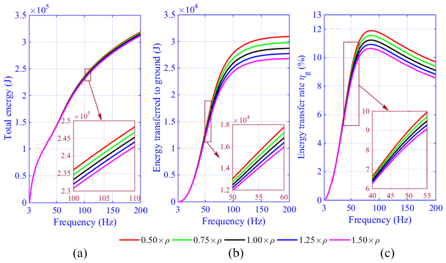
Effects of soil density on energy transfer at different frequencies: (a) total energy, (b) energy transferred to ground, and (c) energy transfer rate.
Conclusion
In this article, a model of vibrator-ground system considering frequency is established, and calculating methods and parameter effects of energy transfer are proposed. Results show the following:
The model considering frequency changes is developed based on half-space theory, and field test shows that this model can successfully describe the interaction between the vibrator and the ground throughout the sweep frequency.
The total work done by the hydraulic force on the vibrator-ground system in the frequency band of 3–200 Hz is 3.156 × 10⁵ J, and 9.11% of the energy is transferred to the ground.
The reaction mass with light weight can significantly increase the total energy, but heavier reaction mass generates more energy to ground. Baseplate with small mass not only helps the vibrator to transmit energy uniformly but also generates more ground energy above 100 Hz.
Large baseplate area can improve the interaction between the baseplate and the ground to increase the energy transferred to the ground. The effect of soil on ground energy in low-frequency band is mainly dominated by its elastic modulus, and both the elastic modulus and density of soil have great effects on energy transferred to ground at high frequencies.
Footnotes
Declaration of Conflicting Interests
The author(s) declared no potential conflicts of interest with respect to the research, authorship, and/or publication of this article.
Funding
The author(s) disclosed receipt of the following financial support for the research, authorship, and/or publication of this article: This work is supported by the National Natural Science Foundation of China (grant no. 41902326) and the China National Petroleum Corporation (grant nos. 2018B3401 and 2018E2106).
