



Abstract
Reduced web section (RWS) connections and welded flange plate (WFP) connections can both effectively improve the seismic performance of a structure by moving plastic hinges to a predetermined location away from the column face. In this paper, two kinds of steel frames—with RWS connections and WFP connections—as well as different frames with welded unreinforced flange connections were studied through seismic fragility analysis. The numerical simulation was conducted by using multiscale FE modelling. Based on the incremental dynamic analysis and pushover analysis methods, probabilistic seismic demand analysis and seismic capability analysis were carried out, respectively. Finally, combined with the above analysis results, probabilistic seismic fragility analysis was conducted on the frame models. The results showed that the RWS connection and WFP connection (without double plates) have little influence on reducing the maximum inter-storey drift ratio under earthquake action. RWS connections slightly reduce the seismic capability in non-collapse stages and improve the seismic collapse resistance of a structure, which exhibits good structural ductility. WFP connections can comprehensively improve the seismic capability of a structure, but the seismic collapse resistance is worse than that of RWS connections when the structure has a large number of storeys. The frame with WFP connections has a lower failure probability at every seismic limit state, while the frame with RWS connections sacrifices some of its structural safety in non-collapse stages to reduce the collapse probability.
Keywords
Introduction
In the 1994 Northridge earthquake and the 1995 Hyogo-ken Nanbu earthquake, many steel structures were severely damaged or destroyed. By investigating these structures, Miller (1998) found that brittle failure occurred in many beam-to-column connections. Since these earthquakes, much research (Jones et al., 2002; Popov et al., 1998) has been conducted to steel frame connections to move the plastic hinge away from the column face, shear panel zone, and the main connection components including welding areas, plates and bolts.
The existing steel beam-to-column connections move the plastic hinge by using the reinforced or weakened models of connections. Reduced web section (RWS) connections are an example of the weakened model. In an RWS connection, four local plastic hinges are formed in the vicinity of the web opening within the perforated beam under Vierendeel action. The opening size and the distance between the opening and the column face both have a significant effect on the capacity and behavior of the connection (Boushehri et al., 2019; Tsavdaridis et al., 2014). Naughton et al. (2017) carried out a series of non-linear static pushover analyses and found that, in low- to mid-rise frames, RWS connections performed satisfactorily without compromising the overall strength capacity of the frames. Chung et al. (2003) found that the shear stress distribution changed on the reduced section of the RWS connection, and the proportion of shear force borne by the flange of the beam increased. Tsavdaridis and Papadopoulos (2016) found that connections with cellular beams behave in a satisfactory manner and provide enhanced performance in terms of the stress distribution when subjected to cyclic loading. Shin et al. (2017) and Tsavdaridis et al. (2017) investigated the seismic toughness and failure mechanism of the connections, which contain the openings with different shapes, sizes, distributions, and numbers. The feasibility and seismic performance of RWS connections were investigated through experimentation and numerical simulation, and the research results indicate that RWS connections exhibit good performance and practicality in the field of earthquake-resistant structures (Kumar and Rao, 2006; Wang et al., 2007; Yang et al., 2009). Moreover, the manufacturing process of RWS connections is rather simple; thus ensuring the high quality construction (Yang et al., 2007).
Welded flange plate (WFP) connections are an example of the reinforced connection. It is designed to strengthen the connection by setting a horizontal stiffening plate at the flange of the beam end. Instead of being directly connected, the flanges of the beam and column are transitively connected by the reinforced flange plate. This design not only increases the section modulus of the beam end but also avoids defects caused by the welding of the beam-column flanges in the connection (Kim et al., 2002a). The seismic design concept of “strong connection and weak member” in American (FEMA-350, 2000) and Chinese (GB50011-2010, 2010) seismic codes is followed by this model’s plastic hinge being moved outward, away from the column face. Kim et al. (2002b) conducted full-scale quasi-static tests on WFP connections and found that a reinforced flange plate had the best performance when the shape was rectangular. Hedayat et al. (2018) carried out a parametric study on the strength and ductility of WFP connections in the case of utilizing deep beams based on a finite element method. Schneider and Teeraparbwong (2002) carried out an experiment on the failure modes and nonlinear performance of the connection and indicated that all cases should meet ductility requirements of 3% rad plastic rotation angle and 5% rad total rotation angle. Kosarieh et al. (2015) found that the cyclic behaviors of WFP connections including hysteresis loops and energy dissipation were not affected significantly by increasing column axial load.
The seismic fragility of a structure refers to the probability of reaching a certain failure state under the action of ground motion of specific intensity. It provides a new way, from the perspective of probability, to evaluate the seismic performance of structures and can comprehensively consider various factors to investigate the probability of failure states of structures under the action of different earthquake intensities. Presently, research on the seismic performance of RWS connections and WFP connections is evolving. However, research on the overall seismic performance of the structures with the two connections is limited to deterministic analysis. The randomness of seismic action is not fully considered in a large enough sample space, so the obtained results cannot fully determine the seismic performance of the structures. Although the two connections can both improve the seismic performance of a structure by moving plastic hinges to a predetermined location away from the column face, the bearing capacity and ductility of them are different and it is not known which connection performs better. As a result, it is important to compare the reliability of the structures under seismic action by seismic fragility analysis.
Methodology
In this paper, three kinds of plane steel frame structures—with RWS connections, WFP connections, and WUF connections—were established using multiscale FE modelling. First, the probabilistic seismic demand of each structure was analysed by using incremental dynamic analysis (IDA). Next, the seismic capability of each structural model was analysed by utilizing the pushover analysis method, and the damage states and limit states were determined according to evaluation criteria. Finally, through a logarithmic linear regression of the data obtained from the probabilistic seismic demand analysis, the logarithmic relation among the seismic demand parameters of the structure and the ground motion intensity parameters was established. Combined with the results of the above analysis, the seismic fragility can be calculated, and the fragility curves can be drawn. The implementation steps for the seismic fragility analysis of these structures are shown in detail in Figure 1.
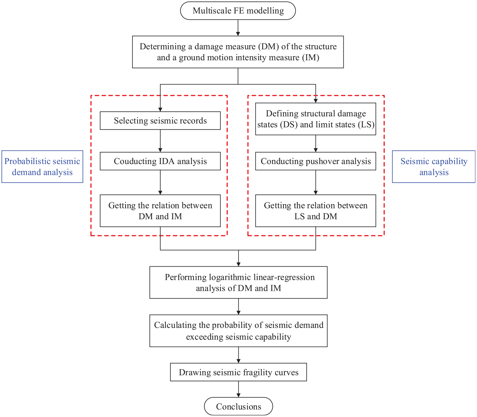
Implementation steps of seismic fragility analysis.
FE model and validation
Multiscale FE model
The main idea of multiscale FE modelling is to establish detailed models for the structure part to be studied, and to adopt rough models for the remaining parts that have little influence on the research, then units of different scales can work together through appropriate connections, so as to realize an effective simulation of multiple scales. It is a reasonable way to balance the accuracy and efficiency of simulation (Ladeveze et al., 2002).
Since the beam-column element model cannot accurately simulate the complex connection, and it is not easy to simulate with a large number of overall structural samples by the detailed model, the three-dimensional multiscale model of a plane steel moment-resisting frame established in ABAQUS FE software was adopted herein, as shown in Figure 2(a). S4R shell elements were adopted for the beam-to-column connection, while B31 beam-column elements were adopted for the remaining beams and columns. The S4R shell element is a 4-node reduced integration element that has good reliability and adaptability in the modelling of thin shells and thick shells. Therefore, the S4R element can be used to ensure high accuracy in the connection area to be studied. The B31 beam-column element is a 2-node spatial linear element; using this type of element at the positions of beams and columns away from the connection can ensure a high computational efficiency and ensure that a large amount of computational resources are devoted to the connection. A proper contact for the interface between two types of elements is the foundation for an analysis with the multiscale FE model. The contact endpoint of the beam-column element and the contact surface of the shell element were set as a reference node and a slave surface, respectively, and the coupling function in the interaction module of ABAQUS was employed to coordinate the contact interface so that the two parts can work together. The coupling type was set as kinematic, and the motion of a collection of nodes on the slave surface was coupled to the motion of the reference node with all 6 degrees of freedom (i.e. three translations and three rotations) constrained.
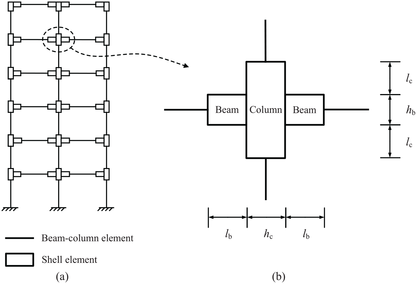
Multiscale element model: (a) schematic elevation of a plane frame structure model, and (b) geometrical dimensions of the shell element part.
Figure 2(b) depicts the geometrical dimensions of the shell element in the multiscale model of the interior connection, where hb and hc represent the heights of the beam section and the column section, respectively and lb and lc represent the lengths of the remaining beams and columns, respectively, in the shell element model. The exterior connections in the frame, such as the connections of side columns and top beams, can be represented in a similar way. The length of the beam-column element can be calculated according to the dimensions of the shell element part and the span and floor height of the structure. It is worth noting that the length of the shell element model of beam or column can be set to a small value while it should be no less than the length that can reflect the characteristics of the connection.
To improve the calculation efficiency and highlight the influence of the connection type on the structure performance, factors such as high-strength bolts, shear tabs, access hole and welds were ignored in the FE modelling. Since the RWS, WFP and WUF connections are all rigid beam-to-column connections, the contact interfaces between the beams and columns in the shell element parts of these connection models can be simplified by tying the surface of the beam end to the column face.
Model validation of the RWS connection
To verify the accuracy of the multiscale FE model of the RWS connection, the experimental specimen denoted SPC1 from Li et al. (2011), a fully welded and single-sided moment RWS connection, was introduced. A circular opening with a radius of 125 mm was set in the beam web 385 mm from the column face. The test setup for specimen SPC1 is shown in Figure 3(a).
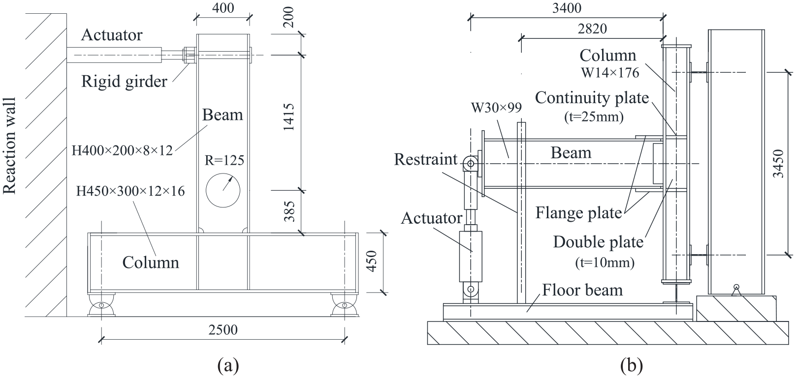
Experimental setup: (a) RWS connection of specimen SPC1 (Li et al., 2011), and (b) WFP connection of specimen RC6 (Kim et al., 2002a).
The lc and lb values of the multiscale FE model were 400 mm and 650 mm, respectively. To simulate the presence of the web opening, a circular disc was cut off in the beam shell element corresponding to the specimen SPC1. The connections of components including the beam, column and continuity plates were modelled as tie constraints to simulate welding. To further enhance the numerical analysis efficiency of the non-connection area and ensure accuracy in the connection area, the mesh was refined in the shell elements and made to be coarse in the beam-column elements. The von Mises yield criterion was adopted. In accordance with the material model proposed in the literature, the isotropic hardening material model was assumed and a trilinear stress-strain relation considering the hardening stage was adopted. The properties for the steel material were uniformly set as: Young’s Modulus E = 200 GPa, Poisson’s ratio γ = 0.3, yield strength fy = 259.8 MPa, Initial hardening strain εt = 0.013, and secant modulus Et = 6.18 GPa. A nonlinear full Newton-Raphson direct method was used for the analysis. Increment step size was set to automatic to be controlled by the program. Except for the rotational degree of freedom in the plane, all the other degrees of freedom were restrained at both ends of the column. The cross section of the beam end in the loading position was tied to a reference point and then the cyclic displacement load used in the test was applied to the reference point.
Model validation of the WFP connection
Specimen RC6 from Kim et al. (2002a) was introduced to verify the accuracy of the multiscale FE model of the WFP connection. Specimen RC6 was a single-sided WFP connection and tested upright, as shown in Figure 3(b). The flange plate had a rectangular surface shape with a length of 380 mm and a width of 337 mm, and the plate thickness was 25 mm.
The lc and lb values of the WFP connection were 400 mm and 800 mm, respectively. In the process of modelling, the beam flange and the flange plate were tied together, then the end of the flange plate was tied to the column face to realize the indirect connection between the beam flange and the column. It is worth noting that the mesh size needs to be refined in the areas near the plastic hinge and where there will be a large stress and deformation, such as the flange plates and the beam sections influenced by the reinforcement. A Young’s modulus of E = 190 GPa and a Poisson’s ratio of γ = 0.3 were assigned to the steel material in the elastic stage. The material nonlinearity of the beam flange (fy = 369 MPa and fu = 493 MPa), beam web (fy = 427 MPa and fu = 506 MPa), column flange (fy = 350 MPa and fu = 503 MPa) and column web (fy = 386 MPa and fu = 497 MPa) was considered during the analysis by adopting a bilinear stress-strain relation. The cyclic displacement in accordance with the SAC loading protocol recomennded in FEMA-350 (2000) was loaded at the beam end. In addition, the degrees of freedom of out-of-plane traslation were restrained at the beam in the distance of 580 mm from the beam end to prevent lateral torsional buckling. The other detailed modelling method employed for the WFP connection can refer to that employed for the RWS connection.
Validation results
Figure 4(a) shows the results of a comparison between the multiscale FE model and the experimental test of the RWS connection under the action of a low cyclic load. In the FE model, the elastic stiffness of the RWS connection was 1.12 × 10⁴ kN/m, 7.1% higher than the test result of 1.05 × 10⁴ kN/m, and the connection bearing capacity was 191.3 kN, 6.0% lower than the test result of 203.5 kN. The hysteretic curve of the FE model shows strength degradation when the displacement load amplitude reaches 35 mm, which was also reflected in the test, so it can be concluded that the hysteretic curve of the multiscale FE model of the RWS connection is in good agreement with the test curve. In addition, by comparing the failure modes of the RWS connection between the FE model and test result at the end of loading, as shown in Figure 5(a), the plastic hinges and local buckling were both formed in the vicinity of the web opening while the other zone remained elastic, indicating the mechanism of Vierendeel hinges failure. It can be concluded that the multiscale FE model can accurately simulate the plastic hinge characteristics of the RWS connection in the vicinity of the opening.
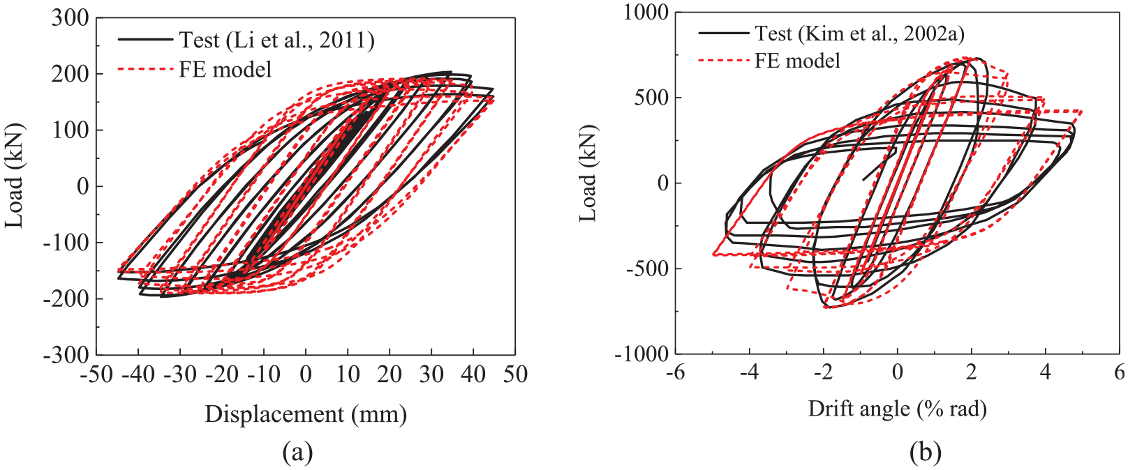
Comparison of the hysteretic curves: (a) RWS connection, and (b) WFP connection.
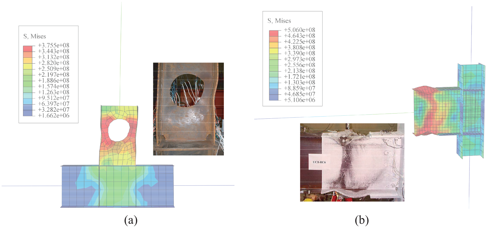
Comparison of the failure modes: (a) RWS connection, and (b) WFP connection.
Figure 4(b) depicts the hysteretic curve of the FE model and the test curve for the WFP connection. The elastic stiffnesses of the connection in the FE model and the test were 538.4 kN/rad and 546.3 kN/rad, respectively, with an error of 1.4%, and the connection bearing capacities in the two cases were 734.1 kN and 730.0 kN, respectively, with an error of only 0.6%. Moreover, the FE model hysteretic curve also reflects significant strength degradation, similar to the test curve. By observing the WFP connection failure modes of the FE model and test result shown in Figure 5(b), it can be found that both the FE model and the test specimen resulted in local buckling at the beam section away from the column face. Their plastic hinges were both formed on the beam near the edge of the flange plates, while the column, beam end and flange plates all remained elastic.
According to the results of the comparison between the two connections in the FE models and the tests, it can be concluded that the multiscale FE model can effectively simulate the hysteresis performance and plastic hinge characteristics of these two modified beam-to-column connections.
Probabilistic seismic demand analysis
Uncertainty of the seismic response
There are many uncertainties in seismic fragility analysis, such as the uncertainty of structural material performance, geometric size, boundary conditions, ground motion, and how the model is analysed; these uncertainties will lead to randomness of structural dynamic response. Many studies (Katsanos et al., 2010; Mangalathu et al., 2018) have conducted detailed sensitivity analyses of structural seismic responses to various factors of uncertainty, and the results have shown that the uncertainty of ground motion is generally considered the main source of the uncertainty affecting the seismic responses of structures, while other uncertainties have relatively little impact on the probabilistic seismic demand analysis. To simplify the analysis of uncertainties herein, only the decisive uncertainty of the ground motion was considered in this paper.
Design of the connections
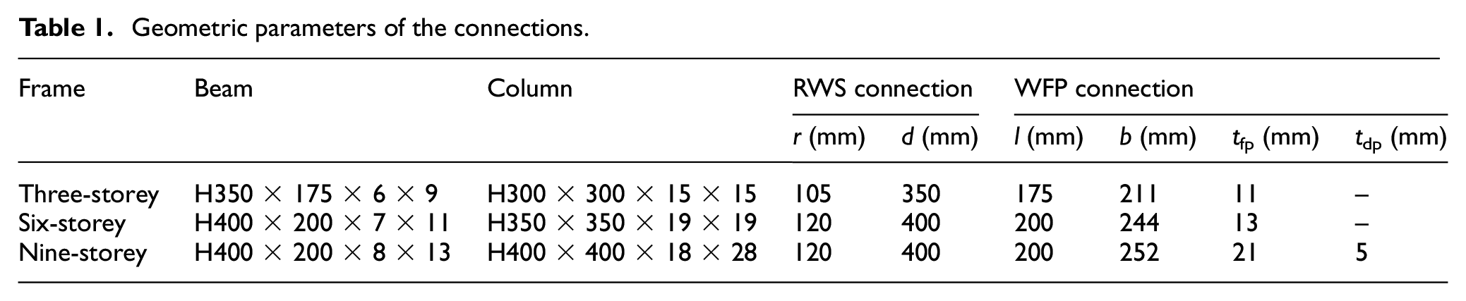
Three plane steel moment-resisting frames with different heights were designed: a three-storey two-span frame, a six-storey two-span frame and a nine-storey three-span frame. The height and span of each frame were 3.5 m and 5.0 m, respectively. The original type of the beam-to-column connection employed in these frames was the WUF-W connection, and the RWS connection and WFP connection were based on the modified design. The modified design process for the WFP connection can be referred to FEMA-350 (2000), which clearly specifies the dimensions of the flange plates and double plates. For RWS connections, although they are mentioned in FEMA-350 (2000), no further details on the dimensions of the web opening are given. It is worth noting that the performance of the RWS connection is determined by the size and position of the web opening, and the determination of the two parameters requires that the connection must have a sufficient bearing capacity while forming effective plastic hinges away from the column face. Studies (Li et al., 2011; Yang et al., 2009) have indicated that RWS connections can meet the design requirements if the opening radius is between 0.25 hb and 0.35 hb and the distance between the center of the opening and the column face is approximately 1.0 hb. Therefore, the opening radius and the distance from the column face of the RWS connection herein were set to 0.30 hb and 1.0 hb, respectively. The configuration details of the connections are drawn in Figure 6 and summarized in Table 1. Each connection was checked to meet the design requirements and the plastic hinge can appear in the predetermined position.
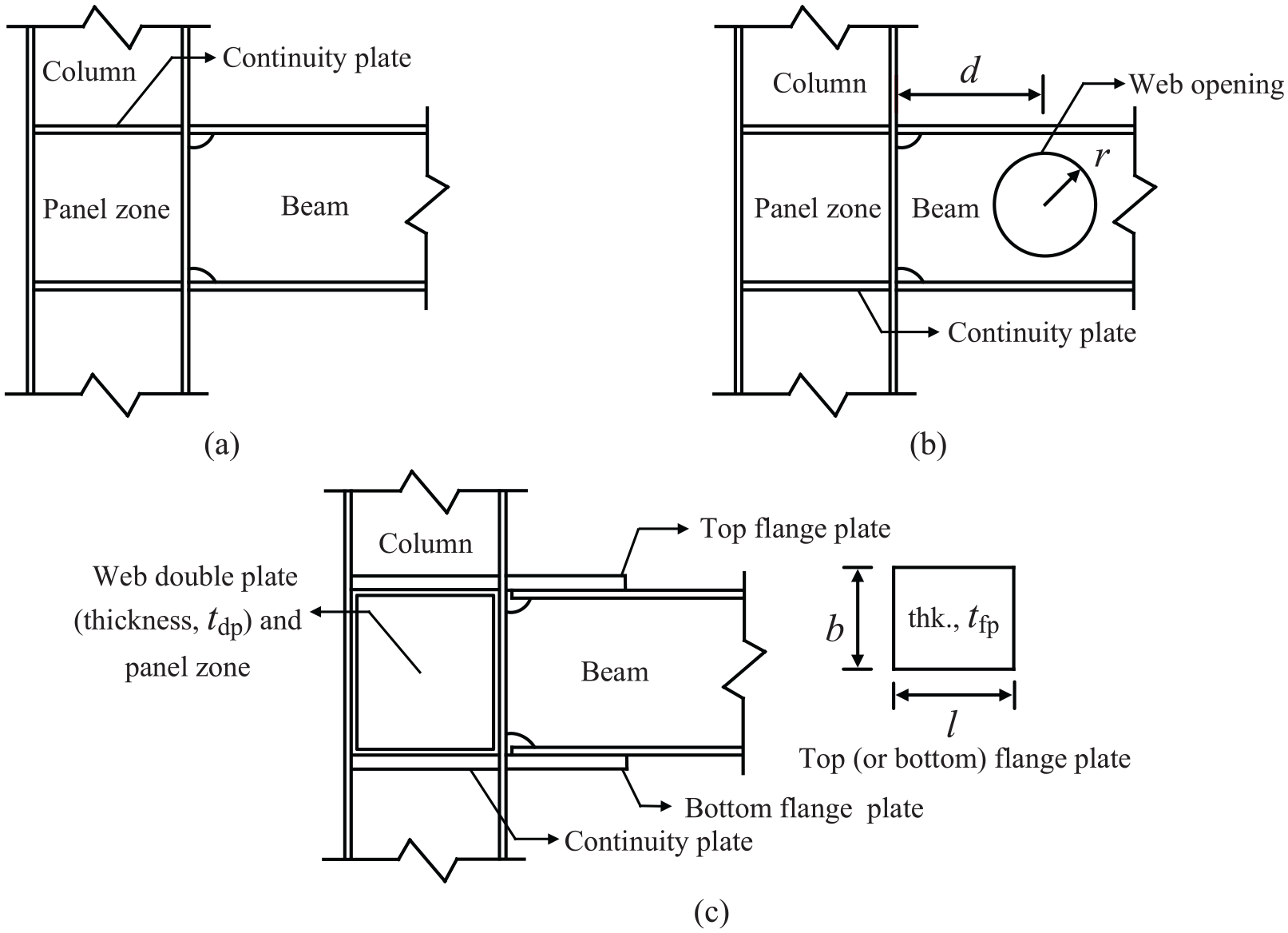
Details of the configurations: (a) WUF connection, (b) RWS connection, and (c) WFP connection.
Geometric parameters of the connections.
IDA analysis
The material properties of the specimens were the same as those employed by Li et al. (2011), and the multiscale FE modelling method was referred to the details mentioned above. Herein, the lc value of each specimen was equal to the column height and lb was twice the beam height. By observing the results of preliminary nonlinear elastoplastic analysis, the lengths can reflect the characteristics of plastic hinges on the shell element and the changes of stress and strain around the plastic hinge. The uniformly distributed linear load on the beam was assumed to be 50 kN/m. The seismic time-history acceleration, which was directed one way (horizontal and parallel to the plane frame), was applied to the column foot, and the remaining degrees of freedom of the column foot were fixed. To simulate the out-of-plane constraints of the floor slabs, the out-of-plane displacement and rotational freedom of all connections and beam midpoints were constrained. The dynamic implicit method using the Newton-Raphson approach was adopted for the seismic time-history analysis. The Rayleigh damping coefficient was adopted, which can be calculated according to the first and second natural vibration periods of the structure and a damping ratio of 0.05. Each specimen was represented by the structure type and the number of storeys. For example, FWUF-6 represents the 6-storey frame with WUF connections.
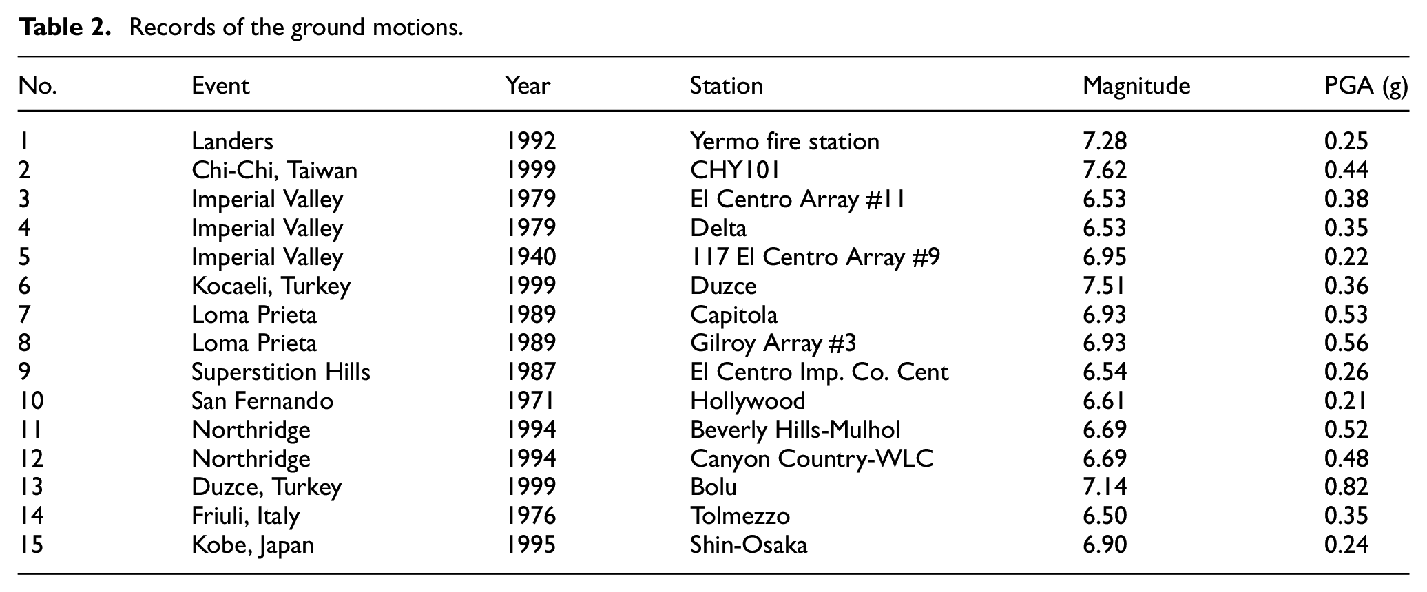
Seismic peak ground acceleration (PGA) was taken as the intensity parameter of ground motion, and the maximum inter-storey drift ratio (MIDR) of the structure was taken as the seismic demand parameter of the structure. Existing study (Luco and Cornell, 2000) have shown that for buildings of medium height, 10 to 20 seismic records would usually be sufficient to assess the seismic requirements of a structure when an appropriate and effective seismic intensity index is used. It is assumed that the seismic intensity of structure sites is 7 degrees, and the characteristic period is 0.40 s. Referring to the code of ATC-63 (2007) in selecting seismic waves, 15 seismic records that met the requirements were selected as shown in Table 2, and the response spectra of the seismic records in rare earthquakes are shown in Figure 7. The curve of every single response spectrum is quite different from each other, which guarantees the diversity of ground motion recording samples and makes the conclusion obtained through uncertainty analysis more representative. The mean response spectrum curve is close to the designed response spectrum curve, which can make the probabilistic seismic demand analysis more reliable.
Records of the ground motions.
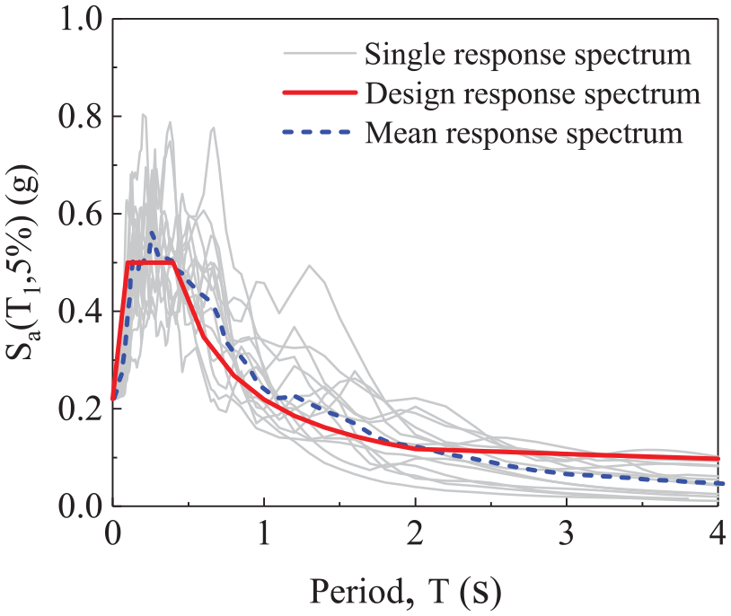
Response spectra of the seismic records.
Amplitude modulation was carried out for each ground motion record, and the peak acceleration after amplitude modulation was seven levels, namely 0.1 g, 0.2 g, 0.3 g, 0.4 g, 0.5 g, 0.6 g, and 0.7 g. The specific amplitude modulation method can be described as:

where a(t) is the original recorded seismic acceleration; a′(t) is the amplitude modulated seismic acceleration; Amax is the original recorded seismic peak acceleration; A′max is the amplitude modulated seismic peak acceleration.
Results of the IDA analysis
The results of the IDA analysis are shown in Figure 8. The 50% IDA curve is the median curve, while the 16% and 84% curves reflect the degree of dispersion represented by the logarithm of the standard deviation (Vamvatsikos and Cornell, 2004). The IDA curves of each specimen vary greatly, and the MIDR also varies among the different specimens under the same earthquake action, which reflects the uncertainty of the seismic structural response. Although each IDA curve is different in every case, the dispersion and median IDA curves do not differ significantly among the specimens of the same height.
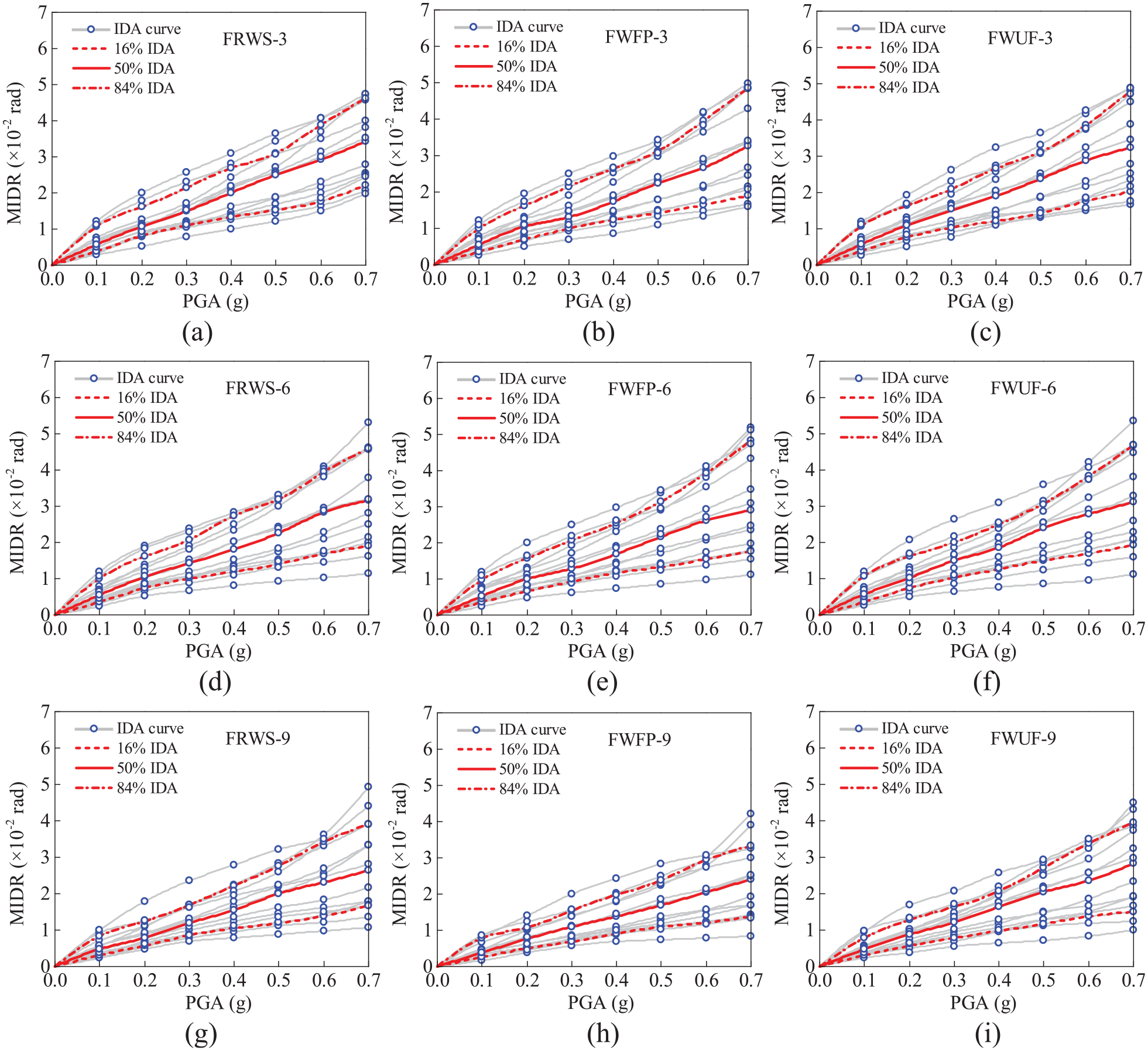
IDA curves of the structures: (a) FRWS-3, (b) FWFP-3, (c) FWUF-3, (d) FRWS-6, (e) FWFP-6, (f) FWUF-6, (g) FRWS-9, (h) FWFP-9, and (i) FWUF-9.
The mean value and variation coefficient of MIDR are summarized in Table 3. The MIDR mean values of FRWS are almost the same as those of FWUF when the structural height is the same, which indicates that the presence of the opening in the beam end of the RWS connection will hardly increase the inter-storey drift of the structures.
MIDR mean value.
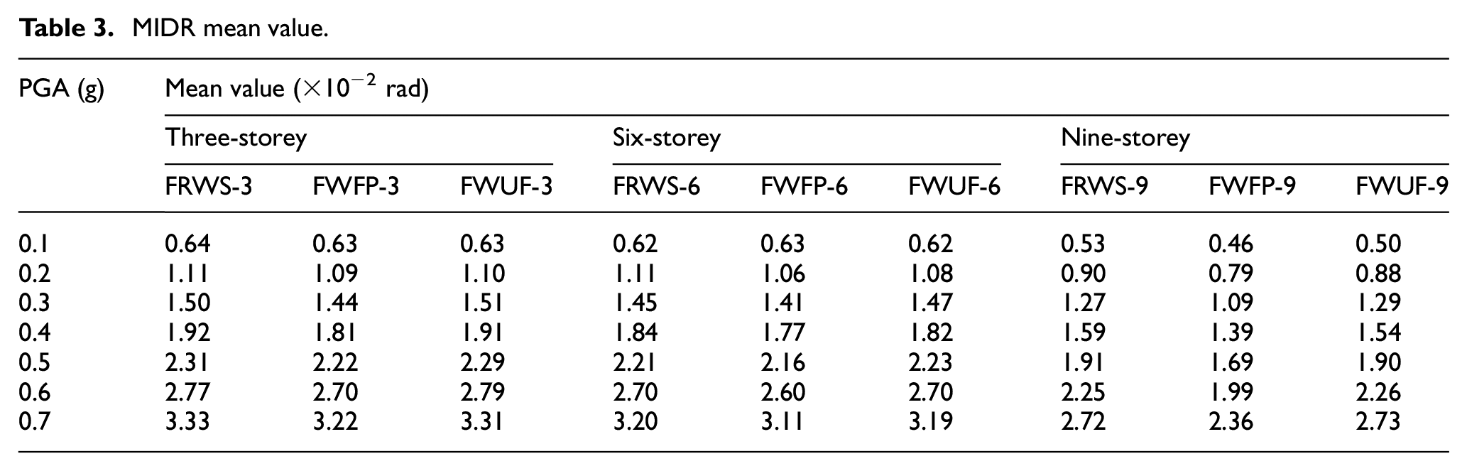
In general, the mean MIDR values of FWFP are smaller than those of FWUF and FRWS; the inter-storey drift of FWFP-3 and FWFP-6 is slightly reduced with the reduction remaining within 5% compared with the other structures of the same height, while the reduction in the MIDR of FWFP-9 reaches approximately 12% because the presence of double plates in the column shear panel zone improves the overall structural stiffness. These results indicate that the flange plates of the WFP connection at the beam end can slightly reduce the inter-storey drift of the structure and that a lager lateral stiffness can be obtained by strengthening the column shear panel zone.
Except for FWFP-9, the mean MIDR values of each specimen of the same height are close. This occurs because the three types of connections are all rigid connections. Although they have different forms, the form has little impact on the natural vibration period, overall stiffness, bearing capacity and dynamic characteristics of the structure, and these connections are far less influential than semi-rigid connections or articulated connections, which would change the connection mode.
Seismic capability analysis
Limit states and damage states
The main goal of seismic capability analysis is to determine the limit state (LS) and damage state (DS) of a structure. The definition of these states should start from the damage state of the members of a structure. ATC-40 (1996) evaluated the seismic performance of a structure according to the development degree, quantity and proportion of plastic hinges. From the perspective of structural members, damage includes the degree, quantity, distribution, and development of plastic hinges. For steel frame structures, the above characteristics of beams and columns are taken into consideration and their damage state under actual seismic load is dependent on the development degree of the plastic hinge. FEMA-356 (2000) has defined three structural damage states: immediate occupancy (IO), life safety (LS) and collapse prevention (CP). The plastic hinge of a member has similar state levels, as shown in Figure 9. In addition, referring to the description of damage degree of structural members in Chinese seismic code (GB50011-2010, 2010), the damage states of structural members were described as intact, slightly damaged, moderately damaged, severely damaged and collapsed.
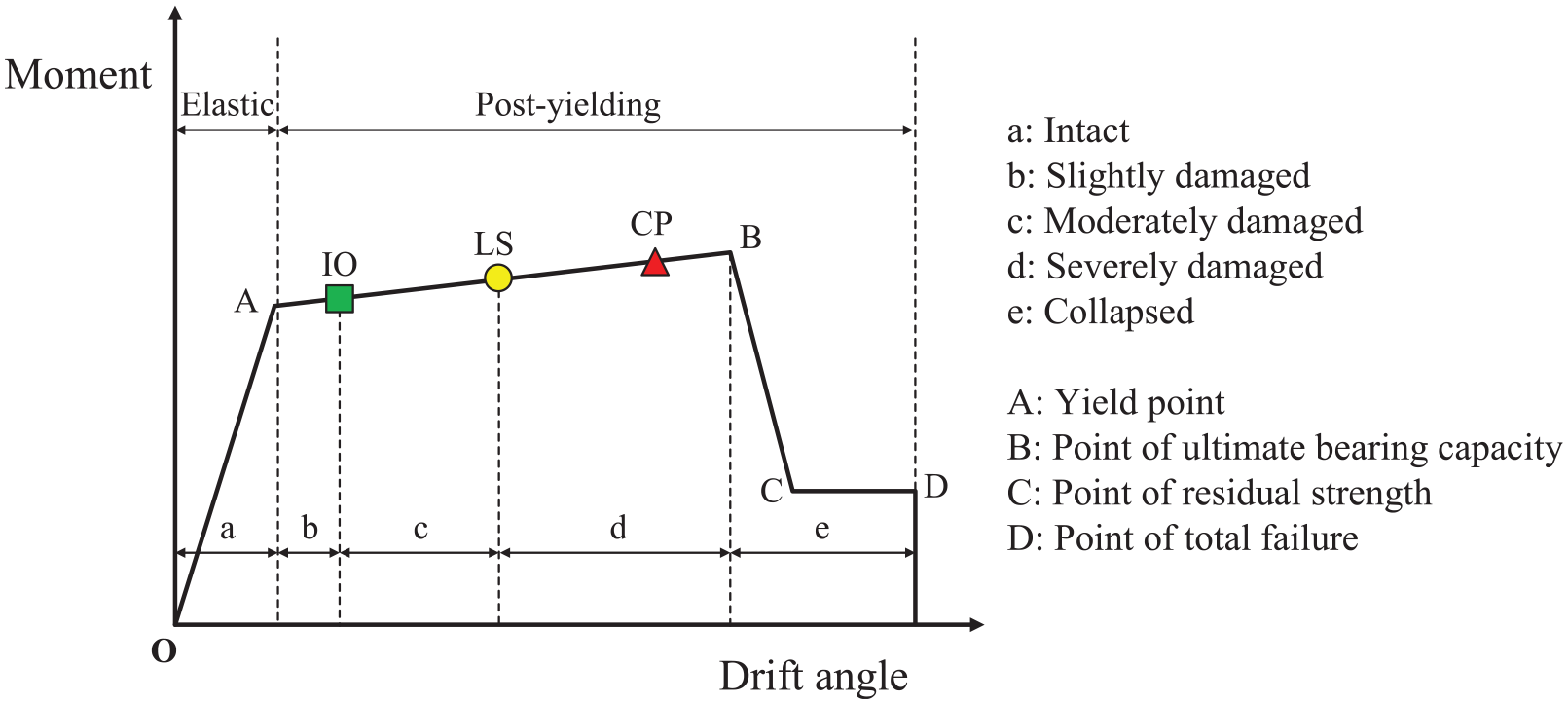
Relation between the plastic hinges and the damage states of structural members.
According to the classification of structural performance levels (FEMA-356, 2000) and the damage state of members, the seismic performance of structures in this paper was divided into four limit states: operational (LS1), immediate occupancy (LS2), life safety (LS3) and collapse prevention (LS4). The damage states of a structure under earthquake action was divided into basically intact (DS1), slightly damaged (DS2), moderately damaged (DS3), severely damaged (DS4), and collapsed (DS5). The relation between the structural limit states and damage states is shown in Figure 10.
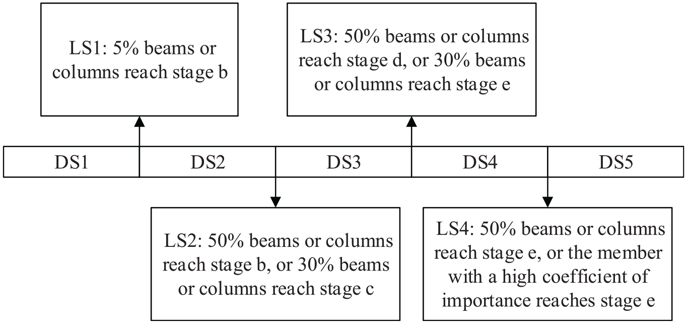
Relation between the structural limit states and damage states.
Results of the pushover analysis
By referring to the descriptions of the structural performance levels in Figures 9 and 10 as well as the results of the pushover analysis, the structural damage process and limit states of each specimen were obtained (see Figure 11). Regardless of the number of storeys in the structure, the MIDR values of LS1–LS3 of FRWS are slightly lower than those of FWUF. This is because the opening in the beam end of the RWS connection makes the plastic hinge develop faster, and the slight, moderate and severe damage states (DS2–DS4) will be advanced. Upon reaching LS4, the corresponding MIDR value of FRWS is significantly higher than that of FWUF, and the gap between the MIDR values gradually enlarges with an increase in the storey number (increasing by 5.9%, 6.4%, and 13.5% when the number of storeys is 3, 6, and 9, respectively). Figure 12 depicts the plastic hinge states of the structural members at LS4. It can be clearly seen that FRWS reaches LS4 because half of the beams reach stage e while the bottom columns are still in stage c or d. In contrast, FWUF reaches LS4 because the middle bottom column reaches stage e. Although the RWS connections fail to improve the seismic performance of the structure at LS1–LS3, these connections are able to reduce the damage levels of the bottom columns at LS4, showing a good collapse resistance performance.
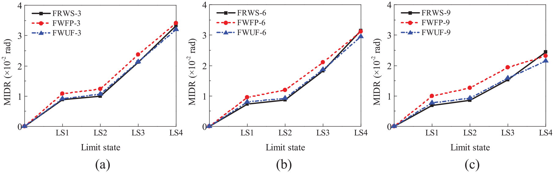
Curves of structural limit states: (a) 3-storey, (b) 6-storey, and (c) 9-storey.
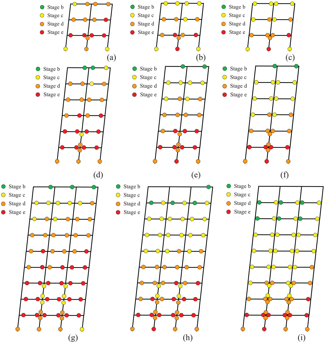
Plastic hinge states of the structures at LS4: (a) FRWS-3, (b) FWFP-3, (c) FWUF-3, (d) FRWS-6, (e) FWFP-6, (f) FWUF-6, (g) FRWS-9, (h) FWFP-9, and (i) FWUF-9.
For FWFP, due to the strengthening of the connection, the development of plastic hinges at the beam end is delayed compared to that for FWUF and FRWS, so the MIDR values of LS1–LS3 are relatively high, which greatly delays the time at which the corresponding damage states are entered. When FWFP reaches LS4, it can be seen from Figure 12 that although the overall degree of damage to the plastic hinges on the beams is higher than that of FWUF, the collapse of the middle bottom column in FWFP means that FWFP shares the same structural collapse mode as FWUF, and with an increase in the number of storeys, the MIDR value of FWFP at LS4 changes from being slightly higher than that of FRWS to lower than that of FRWS.
In conclusion, although the RWS connections cannot improve or even slightly reduce the structural seismic capability in the non-collapse stages, they can improve the seismic collapse resistance of the structure, and the structure exhibits good ductility. The WFP connections improve the seismic capability of the structure in every damage stage due to the strengthening of the connection, but the seismic collapse resistance is worse than that of the structure with the RWS connections when the frame structure has a large number of storeys. It is suggested to enlarge the cross-sectional size of the bottom column or to strengthen the feet of the columns in the structure with the WFP connections.
Seismic fragility analysis
Calculation method of the seismic fragility
Structural seismic fragility is defined as the probability of a structure exceeding a certain damage limit state under the condition of a known earthquake intensity. The damage probability of a structure Pf can be expressed as:

where Rc is the seismic capacity of the structure; Sd is the seismic demand of the structure.
It was assumed that probabilistic seismic demand follows logarithmic normal distribution, and the damage probability of a structure also follows logarithmic normal distribution according to equation (2). The damage probability of a structure can be expressed as:
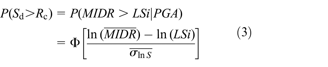
where
The mean seismic demand

where a and b are unknown constants.
Take the logarithm of both sides of equation (4) can be expressed as:

where
Then the damage probability of the structure can be expressed as:

Results of the seismic fragility
Logarithms were taken for PGA and MIDR in the probabilistic seismic demand, and linear regression analysis was performed on the data according to equation (5). The results are shown in Figure 13.
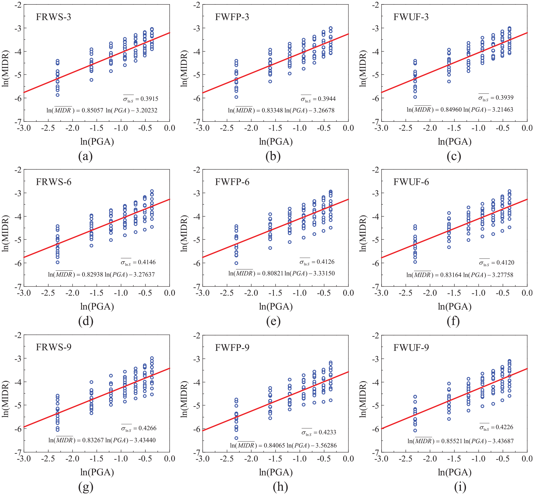
Logarithmic linear regression of seismic demand: (a) FRWS-3, (b) FWFP-3, (c) FWUF-3, (d) FRWS-6, (e) FWFP-6, (f) FWUF-6, (g) FRWS-9, (h) FWFP-9, and (i) FWUF-9.
According to equation (6), the damage probability of each limit state can be obtained, and the seismic fragility curves are shown in Figure 14. Despite the number of storeys, the fragility curves of FWFP at each limit state are all within the range of the curves of FWUF and FRWS, indicating that FWFP has the lowest failure probability at all levels under an earthquake action. The fragility curves of FRWS are slightly higher than those of FWUF at LS1–LS3 and between those of FWUF and FWFP at LS4. This shows that FRWS sacrifices parts of the structural safety in non-collapse stages to reduce the risk of collapse in the event of a collapse and can improve the ductility of the structure.
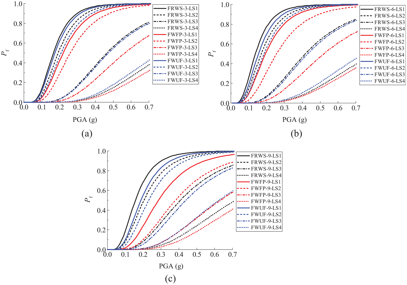
Seismic fragility curves of the structures: (a) 3-storey, (b) 6-storey, and (c) 9-storey.
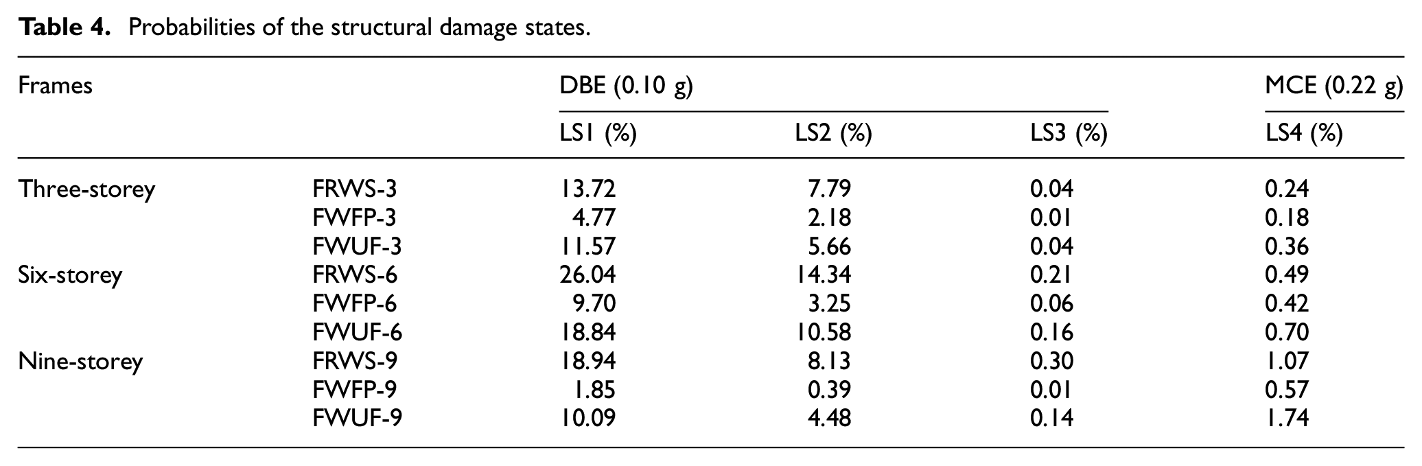
Table 4 lists the failure probabilities of these structures subjected to the design basis earthquake (DBE) and the maximum considered earthquake (MCE), which correspond to PGAs of 0.10 g and 0.22 g, respectively. When experiencing the DBE, FWFP can reduce the structural failure probability many times over, while FRWS has a higher risk of damage at LS1–LS3 than FWUF overall. However, it is worth noting that the calculated negative load carrying capacity of the RWS connection tends to be conservative when the steel-concrete composite effect is neglected (Shaheen et al., 2018). Perhaps in a steel-concrete composite structure, the premature damage to the RWS connections in the non-collapse stage will be improved. The collapse resistance of the structure should be considered when experiencing the MCE. Compared with those of FWUF, the collapse probabilities of FRWS and FWFP are reduced by more than 30% and 40%, respectively, and the improvement is more significant when the structure has a large number of storeys.
Probabilities of the structural damage states.
The WFP connections and RWS connections can be considered in the design of steel beam-to-column connections in practical engineering. The WFP connections can reduce the probability of structural damage at all stages, and it is suggested that the cross-sectional size of the bottom columns of a structure be enlarged or strengthened locally to reduce the collapse risk to a lower extent. Although the RWS connections will increase the failure probability of the structure in the non-collapse stages, they can effectively reduce the collapse risk. Moreover, due to their simple construction process and saving materials, the RWS connections can be employed for steel frame structures that need to reduce costs and prevent collapse during an earthquake. In the design of RWS connections, it is necessary to balance the radius and position of the opening.
Conclusion
Three-, six- and nine-storey steel moment-resisting frames with RWS connections, WFP connections and WUF connections were comparatively studied respectively to conduct seismic fragility analysis. Probabilistic seismic demand analysis and seismic capability analysis were carried out on the structural models by using the IDA and pushover methods, respectively. On this basis, seismic fragility curves were established. The conclusions are as follows:
Compared with the frame with WUF connections, the maximum inter-storey drift ratio of the frame with RWS connections under the same seismic action is almost the same, while the WFP connections without double plates can very slightly reduce the maximum inter-storey drift ratio. In general, the two modified connections without reinforcing column shear panel zones have little influence on reducing the structural inter-storey drift under earthquake action.
There are significant differences in the seismic performance of the steel frames with RWS connections and WFP connections. The RWS connections slightly reduce the structural seismic capability in the non-collapse stages, but they can improve the seismic collapse resistance of a structure, and the structure will exhibit good ductility. The WFP connections comprehensively improve the seismic capability of a structure, but the seismic collapse resistance is worse than that of the structure with RWS connections when the frame structure has a large number of storeys.
The frame with WFP connections has a lower failure probability at every limit state under earthquake action, while the frame with RWS connections sacrifices parts of the structural safety in non-collapse stages to reduce the collapse probability and can improve the ductility of the structure.
Compared with the frame with WUF connections, the collapse probabilities of the frames with RWS connections and WFP connections are reduced by more than 30% and 40%, respectively, and the improvement is more significant when the structure has a large number of storeys.
The WFP connections and the RWS connections are feasible for use in the field of earthquake-resistant structures. The WFP connections can be used in structures that need to improve the seismic safety at every performance level, and it is suggested that the cross-sectional size of the bottom columns of a structure be enlarged or strengthened locally to reduce the collapse risk to a lower extent. Due to their advantages, namely, their good anti-collapse performance, simple construction process, and saving materials, the RWS connections can be employed for steel frame structures that need to reduce costs and prevent collapse during an earthquake.
Footnotes
Declaration of conflicting interests
The author(s) declared no potential conflicts of interest with respect to the research, authorship, and/or publication of this article.
Funding
The author(s) received no financial support for the research, authorship, and/or publication of this article.
